
Recommended
More Related Content
What's hot
What's hot (20)
Viewers also liked
Viewers also liked (12)
Similar to Seperation of losses in three phase induction motor
Similar to Seperation of losses in three phase induction motor (20)
Recently uploaded
Recently uploaded (20)
Seperation of losses in three phase induction motor
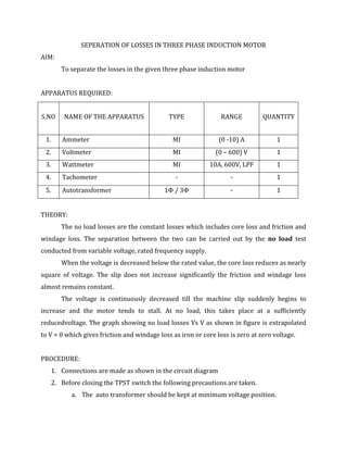
- 1. SEPERATION OF LOSSES IN THREE PHASE INDUCTION MOTOR AIM: To separate the losses in the given three phase induction motor APPARATUS REQUIRED: S.NO NAME OF THE APPARATUS TYPE RANGE QUANTITY 1. Ammeter MI (0 -10) A 1 2. Voltmeter MI (0 – 600) V 1 3. Wattmeter MI 10A, 600V, LPF 1 4. Tachometer - - 1 5. Autotransformer 1Φ / 3Φ - 1 THEORY: The no load losses are the constant losses which includes core loss and friction and windage loss. The separation between the two can be carried out by the no load test conducted from variable voltage, rated frequency supply. When the voltage is decreased below the rated value, the core loss reduces as nearly square of voltage. The slip does not increase significantly the friction and windage loss almost remains constant. The voltage is continuously decreased till the machine slip suddenly begins to increase and the motor tends to stall. At no load, this takes place at a sufficiently reducedvoltage. The graph showing no load losses Vs V as shown in figure is extrapolated to V = 0 which gives friction and windage loss as iron or core loss is zero at zero voltage. PROCEDURE: 1. Connections are made as shown in the circuit diagram 2. Before closing the TPST switch the following precautions are taken. a. The auto transformer should be kept at minimum voltage position.
- 2. b. The motor should be on no load. 3. Close the TPST switch and rated voltage is applied to the motor by adjusting the auto transformer. 4. Note down the ammeter, voltmeter and wattmeter readings ( under no load if one of the wattmeter reads negative interchange the M & L connections and consider this reading as negative). 5. Reduce the applied voltage in steps (of 20V) and note down the corresponding readings. 6. Repeat step 5 till the motor slip suddenly begins to increase and the motor tends to stall. 7. Bring the auto transformer to the minimum position and switch off the supply. 8. Measure stator resistance per phase using voltmeter-ammeter method. CALCULATIONS: Plot Po vs V and extrapolate to V = 0, this will give friction and windage loss P0 watts Pfw V rated V volts Sator resistance per phase ( R1) is mearsured and copper loss is calculated as PCU = 3IO2R1 Then core loss, Pi = PO - Pfw
- 3. TABULATION: Line Voltage Line Current No load power Po S.NO (V) (I) volts amps W1 Watts W2 watts Po = W1 - W2