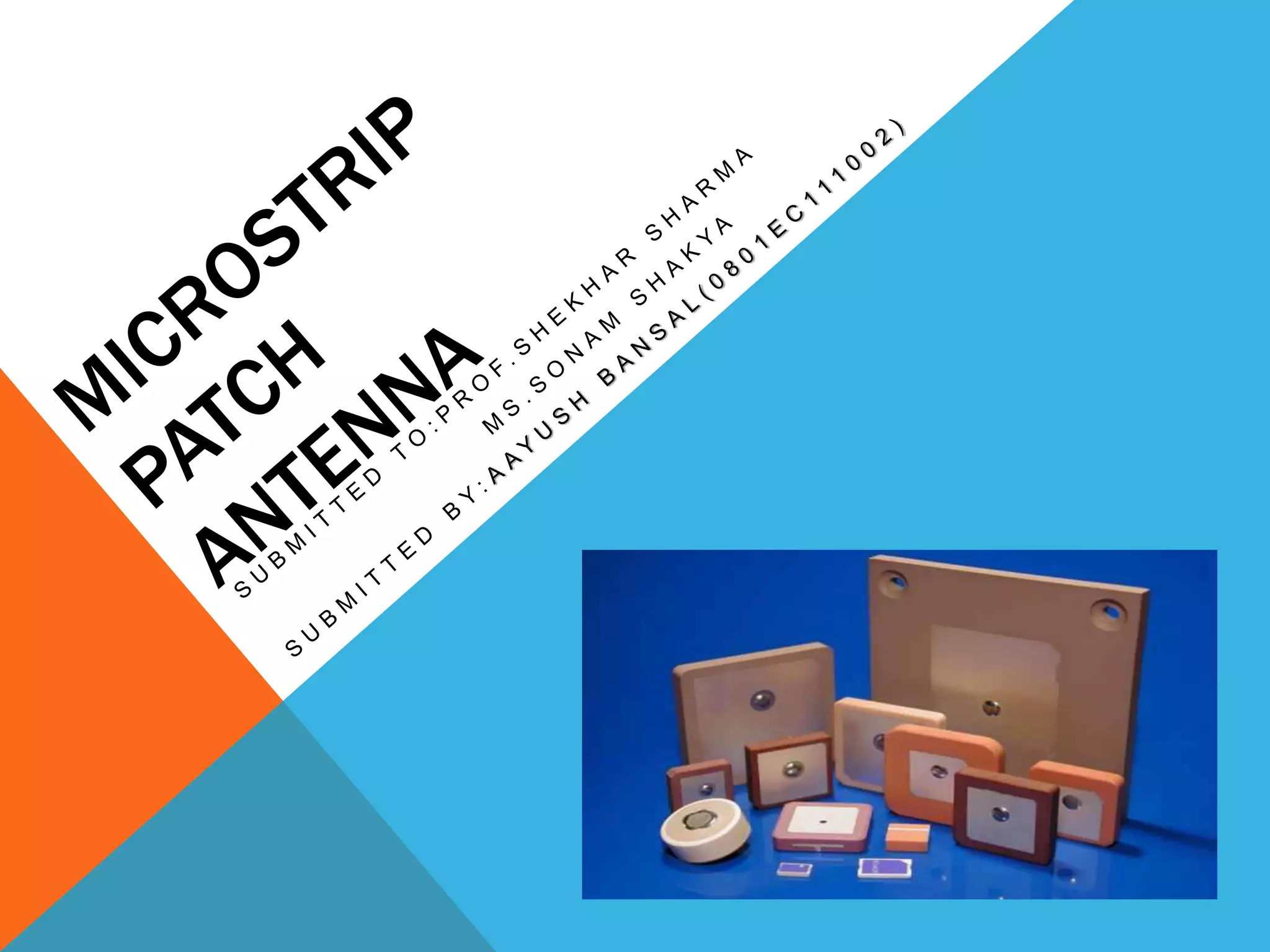
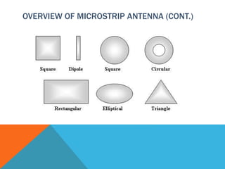
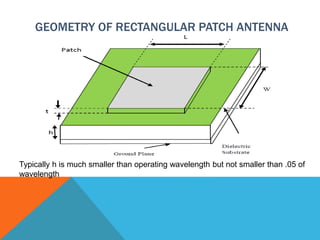
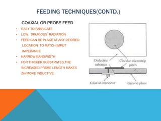
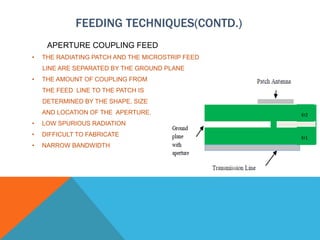
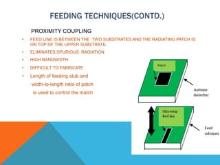
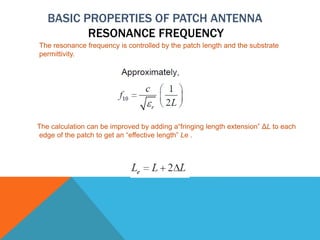
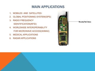
OVERVIEW
• DEFINITION
• GEOMETRY
• ADVANTAGES AND DISADVANTAGES
• FEEDING TECHNIQUES
• BASIC PROPERTIES
• BANDWIDTH IMPROVEMENT
• RADIATION PATTERN
• IMPROVING PERFORMANCE
• MAIN APPLICATIONS
• CONCLUSIONS
• REFERENCES
WHAT IS MICROSTRIP ANTENNA
ALSO CALLED AS ‘PATCH ANTENNAS’
 One of the most useful antennas at microwave
frequencies( f>1 Ghz)
 It consists of a metal ‘patch’ on top of a grounded
dielectric substrate
 The patch may be in variety of shapes but circular
and rectangular are the most common
OVERVIEW OF MICROSTRIP ANTENNA (CONT.)
GEOMETRY OF RECTANGULAR PATCH ANTENNA
Typically h is much smaller than operating wavelength but not smaller than .05 of
wavelength
ADVANTAGES OF PATCH ANTENNA
 Light weight and low volume
 Easy to fabricate(use etching & photolithography)
 Easy to feed(coaxial cable,microstrip line etc.)
 Easy to use in an array or incorporate with other
microstrip circuit elements
 Mechanically robust when mounted on a rigid
surface
DISADVANTAGES OF PATCH ANTENNA
 Narrow bandwidth
 Low efficiency limited by *conductor & dielectric and **surface
wave losses
 Low gain
 Radiation from feeds and junctions
 Low power handling capacity
*Conductor and dielectric losses are more severe for thinner
substrates
**Surface wave losses become more severe for thicker
substrates(unless air or foam is used)
FEEDING TECHNIQUES
MICROSTRIP FEED :
• EASY TO FABRICATE
• SIMPLE TO MATCH BY
CONTROLLING THE INSET POSITION
• RELATIVELY SIMPLE TO MODEL
FEEDING TECHNIQUES(CONTD.)
QUARTER WAVELENGTH FEED
Z1 CAN BE ALTERED BY
CHANGING WIDTH OF
QUARTER WAVELENGTH
STRIP
FEEDING TECHNIQUES(CONTD.)
COAXIAL OR PROBE FEED
• EASY TO FABRICATE
• LOW SPURIOUS RADIATION
• FEED CAN BE PLACE AT ANY DESIRED
LOCATION TO MATCH IMPUT
IMPEDANCE
• NARROW BANDWIDTH
• FOR THICKER SUBSTRATES,THE
INCREASED PROBE LENGTH MAKES
Zin MORE INDUCTIVE
FEEDING TECHNIQUES(CONTD.)
APERTURE COUPLING FEED
• THE RADIATING PATCH AND THE MICROSTRIP FEED
LINE ARE SEPARATED BY THE GROUND PLANE
• THE AMOUNT OF COUPLING FROM
THE FEED LINE TO THE PATCH IS
DETERMINED BY THE SHAPE, SIZE
AND LOCATION OF THE APERTURE.
• LOW SPURIOUS RADIATION
• DIFFICULT TO FABRICATE
• NARROW BANDWIDTH
FEEDING TECHNIQUES(CONTD.)
PROXIMITY COUPLING
• FEED LINE IS BETWEEN THE TWO SUBSTRATES AND THE RADIATING PATCH IS
ON TOP OF THE UPPER SUBSTRATE.
• ELIMINATES SPURIOUS RADIATION
• HIGH BANDWIDTH
• DIFFICULT TO FABRICATE
• Length of feeding stub and
width-to-length ratio of patch
is used to control the match
BASIC PROPERTIES OF PATCH ANTENNA
RESONANCE FREQUENCY
The resonance frequency is controlled by the patch length and the substrate
permittivity.
The calculation can be improved by adding a“fringing length extension” ΔL to each
edge of the patch to get an “effective length” Le .
RESONANT FREQUENCY(CONTD.)
BANDWIDTH
• The bandwidth is directly proportional to substrate
thickness h.
• The bandwidth is inversely proportional to εr (a foam
substrate gives a high bandwidth).
• The bandwidth is directly proportional to the width W.
RESULTS:
• By using a thick foam substrate, bandwidth of about
10% can be achieved.
• By using special feeding techniques (aperture coupling)
and stacked patches, bandwidth of over 50% have been
achieved.
BANDWIDTH IMPROVEMENT
U-SLOT
The introduction of a U-shaped slot
can give a significant bandwidth
(10%-40%).
DOUBLE U-SLOT
A 44% bandwidth was achieved.
BANDWIDTH IMPROVEMENT(CONTD.)
A bandwidth of 34% was achieved
RESONANT INPUT RESISTANCE
• The resonant input resistance is almost independent of the
substrate thickness h.
• The resonant input resistance is proportional to εr.
• The resonant input resistance is directly controlled by the
location of the fed point. (maximum at edges , zero at center
of patch.)
RADIATION PATTERN
• The E-plane pattern is typically broader than the H-
plane pattern.
• The truncation of the ground plane will cause edge
diffraction, which tends to degrade the pattern
RADIATION PATTERN(CONTD.)
E - P L A N E
PAT T E R N
H - P L A N E
PAT T E R N
IMPROVING PERFORMANCE
By Reducing Surface-Wave Excitation and LateraL Radiation by
decreasing dielectric thickness and permittivity
IMPROVING PERFORMANCE(CONTD.)
Reducing surface-wave excitation and lateral radiation
reduces mutual coupling.
MAIN APPLICATIONS
1. MOBILES AND SATELLITES
2. GLOBAL POSITIONING SYSTEM(GPS)
3. RADIO FREQUENCY
IDENTIFICATION(RFID)
4. WORLDWIDE INTEROPERABILITY
FOR MICROWAVE ACCESS(WiMAX)
5. MEDICAL APPLICATIONS
6. RADAR APPLICATIONS
CONCLUSION
• A THEORITICAL AS WELL AS PRACTICAL ASPECT OF MICROSTRIP
PATCH ANTENNA IS PRESENTED
• Lower gain and low power handling capacity can be
overcome through an array configuration.
• Particular microstrip patch antenna can be designed for each
application and different merits are compared with
conventional microwave antenna.
REFERENCES
• C.A. Balanis, Antenna theory: analysis and design, 2nd ed., John Willey and
& Son, Inc., 1997
• James j., and P.S. Hall (Eds), Handbook of microstrip antenna, Peter
Peregrinus, London, UK, 1989.
• J. D. Kraus, R. J. Marhefka, “Antenna for all applications” 3rd Ed., McGraw-
Hill, 2002.
• P.Subbulakshmi , R.Rajkumar : “ Design and characterization of corporate
feed rectangular microstrip patch antenna array antenna”,IEEE International
Conference on Emerging Trends in Computing, Communication and
Nanotechnology,549-552, (ICECCN 2013)
• WWW.ANTENNA-THEORY.COM
Patch antenna

Patch antenna

  • 2.
    OVERVIEW • DEFINITION • GEOMETRY •ADVANTAGES AND DISADVANTAGES • FEEDING TECHNIQUES • BASIC PROPERTIES • BANDWIDTH IMPROVEMENT • RADIATION PATTERN • IMPROVING PERFORMANCE • MAIN APPLICATIONS • CONCLUSIONS • REFERENCES
  • 3.
    WHAT IS MICROSTRIPANTENNA ALSO CALLED AS ‘PATCH ANTENNAS’  One of the most useful antennas at microwave frequencies( f>1 Ghz)  It consists of a metal ‘patch’ on top of a grounded dielectric substrate  The patch may be in variety of shapes but circular and rectangular are the most common
  • 4.
    OVERVIEW OF MICROSTRIPANTENNA (CONT.)
  • 5.
    GEOMETRY OF RECTANGULARPATCH ANTENNA Typically h is much smaller than operating wavelength but not smaller than .05 of wavelength
  • 6.
    ADVANTAGES OF PATCHANTENNA  Light weight and low volume  Easy to fabricate(use etching & photolithography)  Easy to feed(coaxial cable,microstrip line etc.)  Easy to use in an array or incorporate with other microstrip circuit elements  Mechanically robust when mounted on a rigid surface
  • 7.
    DISADVANTAGES OF PATCHANTENNA  Narrow bandwidth  Low efficiency limited by *conductor & dielectric and **surface wave losses  Low gain  Radiation from feeds and junctions  Low power handling capacity *Conductor and dielectric losses are more severe for thinner substrates **Surface wave losses become more severe for thicker substrates(unless air or foam is used)
  • 8.
    FEEDING TECHNIQUES MICROSTRIP FEED: • EASY TO FABRICATE • SIMPLE TO MATCH BY CONTROLLING THE INSET POSITION • RELATIVELY SIMPLE TO MODEL
  • 9.
    FEEDING TECHNIQUES(CONTD.) QUARTER WAVELENGTHFEED Z1 CAN BE ALTERED BY CHANGING WIDTH OF QUARTER WAVELENGTH STRIP
  • 10.
    FEEDING TECHNIQUES(CONTD.) COAXIAL ORPROBE FEED • EASY TO FABRICATE • LOW SPURIOUS RADIATION • FEED CAN BE PLACE AT ANY DESIRED LOCATION TO MATCH IMPUT IMPEDANCE • NARROW BANDWIDTH • FOR THICKER SUBSTRATES,THE INCREASED PROBE LENGTH MAKES Zin MORE INDUCTIVE
  • 11.
    FEEDING TECHNIQUES(CONTD.) APERTURE COUPLINGFEED • THE RADIATING PATCH AND THE MICROSTRIP FEED LINE ARE SEPARATED BY THE GROUND PLANE • THE AMOUNT OF COUPLING FROM THE FEED LINE TO THE PATCH IS DETERMINED BY THE SHAPE, SIZE AND LOCATION OF THE APERTURE. • LOW SPURIOUS RADIATION • DIFFICULT TO FABRICATE • NARROW BANDWIDTH
  • 12.
    FEEDING TECHNIQUES(CONTD.) PROXIMITY COUPLING •FEED LINE IS BETWEEN THE TWO SUBSTRATES AND THE RADIATING PATCH IS ON TOP OF THE UPPER SUBSTRATE. • ELIMINATES SPURIOUS RADIATION • HIGH BANDWIDTH • DIFFICULT TO FABRICATE • Length of feeding stub and width-to-length ratio of patch is used to control the match
  • 13.
    BASIC PROPERTIES OFPATCH ANTENNA RESONANCE FREQUENCY The resonance frequency is controlled by the patch length and the substrate permittivity. The calculation can be improved by adding a“fringing length extension” ΔL to each edge of the patch to get an “effective length” Le .
  • 14.
  • 15.
    BANDWIDTH • The bandwidthis directly proportional to substrate thickness h. • The bandwidth is inversely proportional to εr (a foam substrate gives a high bandwidth). • The bandwidth is directly proportional to the width W. RESULTS: • By using a thick foam substrate, bandwidth of about 10% can be achieved. • By using special feeding techniques (aperture coupling) and stacked patches, bandwidth of over 50% have been achieved.
  • 16.
    BANDWIDTH IMPROVEMENT U-SLOT The introductionof a U-shaped slot can give a significant bandwidth (10%-40%). DOUBLE U-SLOT A 44% bandwidth was achieved.
  • 17.
  • 18.
    RESONANT INPUT RESISTANCE •The resonant input resistance is almost independent of the substrate thickness h. • The resonant input resistance is proportional to εr. • The resonant input resistance is directly controlled by the location of the fed point. (maximum at edges , zero at center of patch.)
  • 19.
    RADIATION PATTERN • TheE-plane pattern is typically broader than the H- plane pattern. • The truncation of the ground plane will cause edge diffraction, which tends to degrade the pattern
  • 20.
    RADIATION PATTERN(CONTD.) E -P L A N E PAT T E R N H - P L A N E PAT T E R N
  • 21.
    IMPROVING PERFORMANCE By ReducingSurface-Wave Excitation and LateraL Radiation by decreasing dielectric thickness and permittivity
  • 22.
    IMPROVING PERFORMANCE(CONTD.) Reducing surface-waveexcitation and lateral radiation reduces mutual coupling.
  • 23.
    MAIN APPLICATIONS 1. MOBILESAND SATELLITES 2. GLOBAL POSITIONING SYSTEM(GPS) 3. RADIO FREQUENCY IDENTIFICATION(RFID) 4. WORLDWIDE INTEROPERABILITY FOR MICROWAVE ACCESS(WiMAX) 5. MEDICAL APPLICATIONS 6. RADAR APPLICATIONS
  • 24.
    CONCLUSION • A THEORITICALAS WELL AS PRACTICAL ASPECT OF MICROSTRIP PATCH ANTENNA IS PRESENTED • Lower gain and low power handling capacity can be overcome through an array configuration. • Particular microstrip patch antenna can be designed for each application and different merits are compared with conventional microwave antenna.
  • 25.
    REFERENCES • C.A. Balanis,Antenna theory: analysis and design, 2nd ed., John Willey and & Son, Inc., 1997 • James j., and P.S. Hall (Eds), Handbook of microstrip antenna, Peter Peregrinus, London, UK, 1989. • J. D. Kraus, R. J. Marhefka, “Antenna for all applications” 3rd Ed., McGraw- Hill, 2002. • P.Subbulakshmi , R.Rajkumar : “ Design and characterization of corporate feed rectangular microstrip patch antenna array antenna”,IEEE International Conference on Emerging Trends in Computing, Communication and Nanotechnology,549-552, (ICECCN 2013) • WWW.ANTENNA-THEORY.COM

Editor's Notes

  • #6 L is resonant dimension.The width W is usually chosen to be larger than L( to get higher bandwidth).typically h is much smaller than wavelength of operation but not smaller than .05 of wavelength.