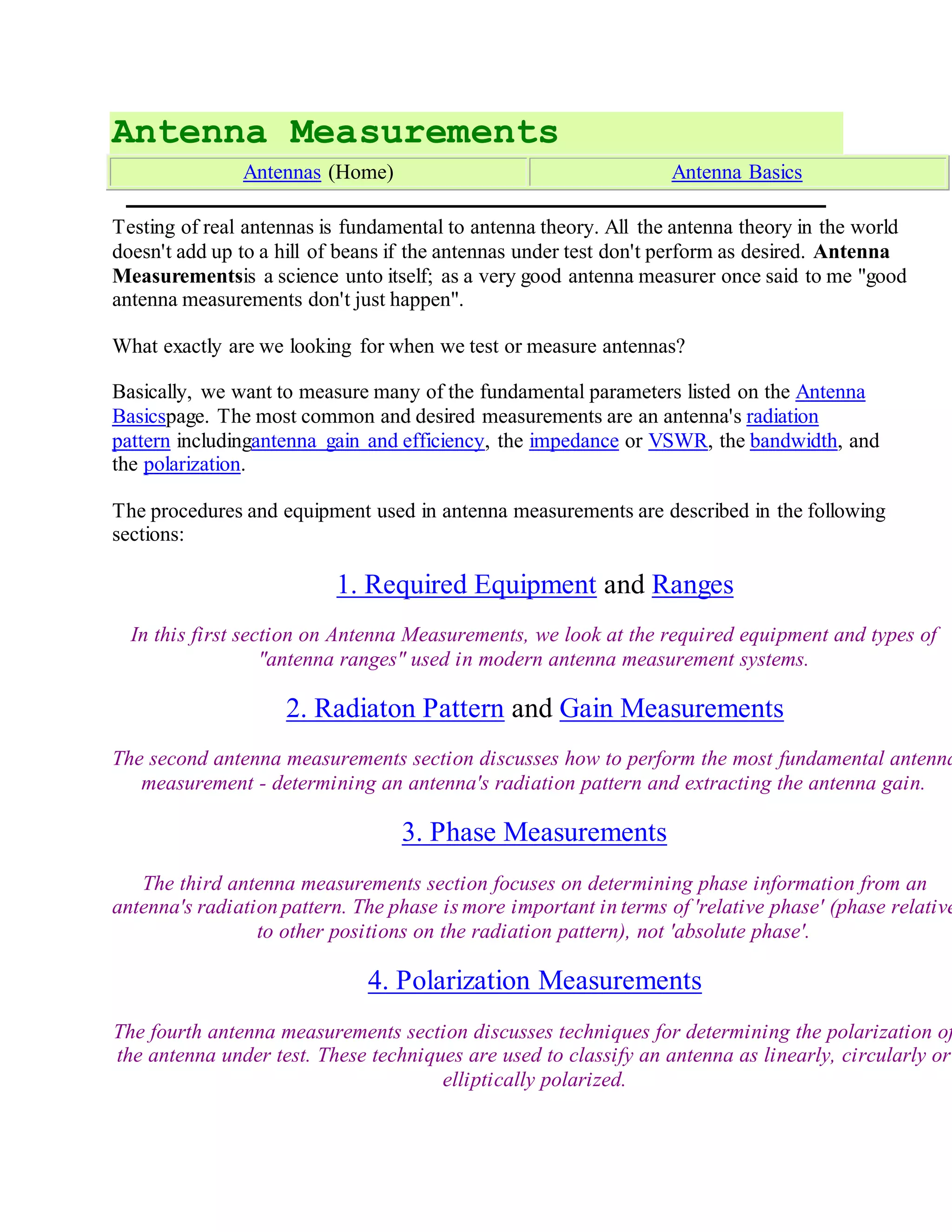
The document discusses antenna measurements and the equipment and facilities required to perform them. Key points:
- Antenna measurements are needed to characterize parameters like radiation pattern, gain, impedance, bandwidth, and polarization.
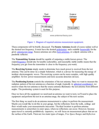
- Required equipment includes a source antenna, transmitter, receiver, and positioning system to rotate the antenna under test.
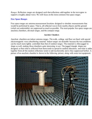
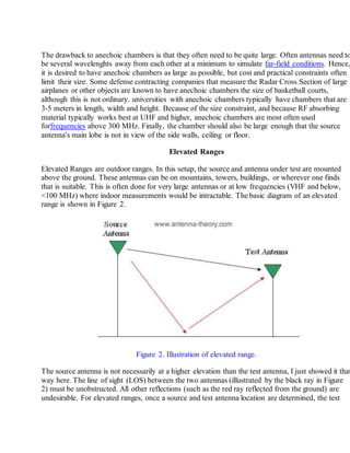
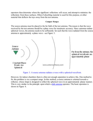
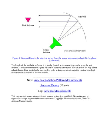
- Facilities for measurements include anechoic chambers (indoor, uses absorbing material), elevated ranges (outdoor, antennas elevated above ground), and compact ranges (uses a reflector to collimate the source antenna's spherical waves into a planar wave).

![Antenna measurement
From Wikipedia, the free encyclopedia
This article needs additionalcitations for verification. Please help improve
this article by adding citations to reliable sources. Unsourced material may be
challenged and removed. (January 2012)
Antenna measurement techniques refers to the testing of antennas to ensure that the antenna
meets specifications or simply to characterize it. Typical parameters of antennas are gain, radiation
pattern, beamwidth, polarization, and impedance.
The antenna pattern is the response of the antenna to a plane wave incident from a given direction
or the relative power density of the wave transmitted by the antenna in a given direction. For a
reciprocal antenna, these two patterns are identical. A multitude of antenna pattern measurement
techniques have been developed. The first technique developed was the far-field range, where the
antenna under test (AUT) is placed in the far-field of a range antenna. Due to the size required to
create a far-field range for large antennas, near-field techniques were developed, which allow the
measurement of the field on a surface close to the antenna (typically 3 to 10 times its wavelength).
This measurement is then predicted to be the same at infinity. A third common method is the
compact range, which uses a reflector to create a field near the AUT that looks approximately like a
plane-wave.
Contents
[hide]
1Far-field range (FF)
2Near-field range (NF)
o 2.1Planar near-field range
2.1.1Rectangular planar scanning
2.1.2Polar planar scanning
2.1.3Bi-polar planar scanning
o 2.2Cylindrical near-field range
o 2.3Spherical near-field range
3Free-space ranges
o 3.1Compact range
o 3.2Elevated range
o 3.3Slant range
4Antenna parameters
o 4.1Radiation pattern
o 4.2Efficiency
o 4.3Bandwidth
o 4.4Directivity
o 4.5Gain
5Physical background
6Calculation of antenna parameters in reception
7See also
8References
9Further reading](https://image.slidesharecdn.com/antennameasurements-160308005130/85/Antenna-measurements-8-320.jpg)
![Far-field range (FF)[edit]
The far-field range was the original antenna measurement technique, and consists of placing the
AUT a long distance away from the instrumentation antenna. Generally, the far-field distance
or Fraunhofer distance, d, is considered to be
,
where D is the maximum dimension of the antenna and is the wavelength of the radio
wave.[1]
Separating the AUT and the instrumentation antenna by this distance reduces the phase
variation across the AUT enough to obtain a reasonably good antenna pattern.
IEEE suggests the use of their antenna measurement standard, document number IEEE-Std-
149-1979 for far-field ranges and measurement set-up for various techniques including ground-
bounce type ranges.
Near-field range (NF)[edit]
Main article: Electromagnetic near-field scanner
Planar near-field range[edit]
Planar near-field measurements are conducted by scanning a small probe antenna over a
planar surface. These measurements are then transformed to the far-field by use of aFourier
transform, or more specifically by applying a method known as stationary phase[2]
to the Laplace
transform . Three basic types of planar scans exist in near field measurements.
Rectangular planar scanning[edit]
The probe moves in the Cartesian coordinate system and its linear movement creates a regular
rectangular sampling grid with a maximum near-field sample spacing of Δx = Δy = λ /2.
Polar planar scanning[edit]
More complicated solution to the rectangular scanning method is the plane polar scanning
method.
Bi-polar planar scanning[edit]
The bi-polar technique is very similar to the plane polar configuration.](https://image.slidesharecdn.com/antennameasurements-160308005130/85/Antenna-measurements-9-320.jpg)
![Cylindrical near-field range[edit]
Cylindrical near-field ranges measure the electric field on a cylindrical surface close to the AUT.
Cylindrical harmonics are used transform these measurements to the far-field.
Spherical near-field range[edit]
Spherical near-field ranges measure the electric field on a spherical surface close to the AUT.
Spherical harmonics are used transform these measurements to the far-field
Free-space ranges[edit]
This section
requiresexpansion.(June 2008)
The formula for electromagnetic radiation dispersion and information is:
Where D=Distance, P=Power, and S=Speed
What this means is that double the communication distance requires four times the power. It
also means double power allows double communication speed (bit rate). Double power is
approx. 3dB (10 log(2) to be exact) increase. Of course in the real world there are all sorts of
other phenomena which enter in, such as Fresnel canceling, path loss, background noise,
etc.](https://image.slidesharecdn.com/antennameasurements-160308005130/85/Antenna-measurements-10-320.jpg)
![Compact range[edit]
A Compact Antenna Test Range (CATR) is a facility which is used to provide convenient
testing of antenna systems at frequencies where obtaining far-field spacing to the AUT
would be infeasible using traditional free space methods. It was invented by Richard C.
Johnson at the Georgia Tech Research Institute.[3]
The CATR uses a source antenna which
radiates a spherical wavefront and one or more secondary reflectors to collimate the
radiated spherical wavefront into a planar wavefront within the desired test zone. One typical
embodiment uses a horn feed antenna and a parabolic reflector to accomplish this.
The CATR is used for microwave and millimeter wave frequencies where the 2 D2
/λ far-field
distance is large, such as with high-gain reflector antennas. The size of the range that is
required can be much less than the size required for a full-size far-field anechoic chamber,
although the cost of fabrication of the specially-designed CATR reflector can be expensive
due to the need to ensure precision of the reflecting surface (typically less than λ/100 RMS
surface accuracy) and to specially treat the edge of the reflector to avoid diffracted waves
which can interfere with the desired beam pattern.
Elevated range[edit]
A means of reducing reflection from waves bouncing off the ground.
Slant range[edit]
A means of eliminating symmetrical wave reflection.
Antenna parameters[edit]
See also: Antenna (radio) § Characteristics
Except for polarization, the SWR is the most easily measured of the parameters above.
Impedance can be measured with specialized equipment, as it relates to the complexSWR.
Measuring radiation pattern requires a sophisticated setup including significant clear space
(enough to put the sensor into the antenna's far field, or an anechoic chamber designed for
antenna measurements), careful study of experiment geometry, and specialized
measurement equipment that rotates the antenna during the measurements.
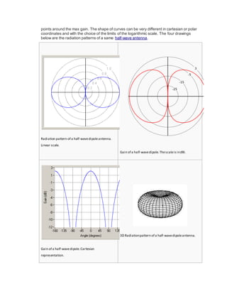
Radiation pattern[edit]
Main article: Radiation pattern
The radiation pattern is a graphical depiction of the relative field strength transmitted from or
received by the antenna, and shows sidelobes and backlobes. As antennas radiate in space
often several curves are necessary to describe the antenna. If the radiation of the antenna is
symmetrical about an axis (as is the case in dipole, helical and someparabolic antennas) a
unique graph is sufficient.
Each antenna supplier/user has different standards as well as plotting formats. Each format
has its own advantages and disadvantages. Radiation pattern of an antenna can be defined
as the locus of all points where the emitted power per unit surface is the same. The radiated
power per unit surface is proportional to the squared electrical field of the electromagnetic
wave. The radiation pattern is the locus of points with the same electrical field. In this
representation, the reference is usually the best angle of emission. It is also possible to
depict the directive gain of the antenna as a function of the direction. Often the gain is given
in decibels.
The graphs can be drawn using cartesian (rectangular) coordinates or a polar plot. This last
one is useful to measure the beamwidth, which is, by convention, the angle at the -3dB](https://image.slidesharecdn.com/antennameasurements-160308005130/85/Antenna-measurements-11-320.jpg)
![Efficiency[edit]
Main article: Antenna efficiency
Efficiency is the ratio of power actually radiated by an antenna to the electrical power it
receives from a transmitter. A dummy load may have an SWR of 1:1 but an efficiency of 0,
as it absorbs all the incident power, producing heat but radiating no RF energy; SWR is no
measure of an antenna's efficiency. Radiation in an antenna is caused by radiation
resistance which cannot be directly measured but is a component of the
total resistance which includes the loss resistance. Loss resistance results in heat
generation rather than radiation, thus reducing efficiency. Mathematically, efficiency is equal
to the radiation resistance divided by total resistance (real part) of the feed-point impedance.
Efficiency is defined as the ratio of the power that is radiated to the total power used by the
antenna; Total power = power radiated + power loss.
Bandwidth[edit]
Main article: Antenna bandwidth
IEEE defines bandwidth as "The range of frequencies within which the performance of
the antenna, with respect to some characteristic, conforms to a specified standard." [4]
In
other words, bandwidth depends on the overall effectiveness of the antenna through a
range of frequencies, so all of these parameters must be understood to fully
characterize the bandwidth capabilities of an antenna. This definition may serve as a
practical definition, however, in practice, bandwidth is typically determined by measuring
a characteristic such as SWR or radiated power over the frequency range of interest.
For example, the SWR bandwidth is typically determined by measuring the frequency
range where the SWR is less than 2:1. Another frequently used value for determining
bandwidth for resonant antennas is the -3dB Return Loss value.
Directivity[edit]
Main article: Directivity
Antenna directivity is the ratio of maximum radiation intensity (power per unit surface)
radiated by the antenna in the maximum direction divided by the intensity radiated by a
hypothetical isotropic antenna radiating the same total power as that antenna. For
example, a hypothetical antenna which had a radiated pattern of a hemisphere (1/2
sphere) would have a directivity of 2. Directivity is a dimensionless ratio and may be
expressed numerically or in decibels (dB). Directivity is identical to the peak value of
the directive gain; these values are specified without respect to antenna efficiency thus
differing from the power gain (or simply "gain") whose value is reduced by an
antenna's efficiency.
Gain[edit]
Main article: Antenna gain
Gain as a parameter measures the directionality of a given antenna. An antenna with a
low gain emits radiation in all directions equally, whereas a high-gain antenna will
preferentially radiate in particular directions. Specifically, the Gain or Power gain of an
antenna is defined as the ratio of the intensity (power per unit surface) radiated by the
antenna in a given direction at an arbitrary distance divided by the intensity radiated at
the same distance by an hypothetical isotropic antenna:](https://image.slidesharecdn.com/antennameasurements-160308005130/85/Antenna-measurements-13-320.jpg)
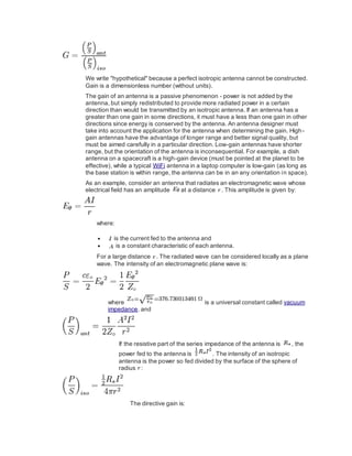
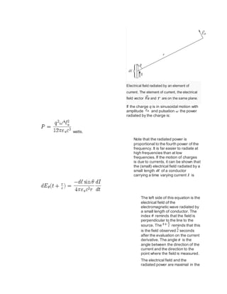
![For the commonly utilized half-wave dipole, the particular
formulation works out to the following, including
its decibel equivalency, expressed as dBi (decibels referenced
toisotropic radiator):
(In most cases 73.13, is adequate)
(Likewise,1.64 and2.15dBi are usually thecitedvalues)
Sometimes, the half-wave dipole is taken as a
reference instead of the isotropic radiator. The gain is
then given in dBd (decibels over dipole):
0 dBd = 2.15 dBi
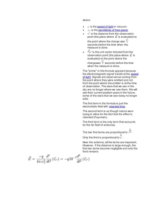
Physical background[edit]
The measured electrical field was radiated seconds
earlier.
The electrical field created by an electric charge
is](https://image.slidesharecdn.com/antennameasurements-160308005130/85/Antenna-measurements-15-320.jpg)
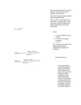
![Calculation of
antenna
parameters in
reception[edit]
The gain in any given
direction and the
impedance at a
given frequency are
the same when the
antenna is used in
transmission or in
reception.
The electric field of an
electromagnetic wave
induces a
small voltage in each
small segment in all
electric conductors.
The induced voltage
depends on the
electrical field and the
conductor length. The
voltage depends also
on the relative
orientation of the
segment and the
electrical field.
Each small voltage
induces a current and
these currents
circulate through a
small part of the
antenna impedance.
The result of all those
currents and tensions
is far from immediate.
However, using
the reciprocity
theorem, it is possible
to prove that the
Thévenin equivalent
circuit of a receiving
antenna is:](https://image.slidesharecdn.com/antennameasurements-160308005130/85/Antenna-measurements-19-320.jpg)
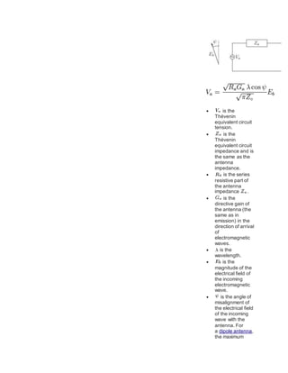
![t circuit, it
can be
shown
that the
maximum
power is
absorbed
by the
antenna
when it is
terminate
d with a
load
matched
to the
antenna
input
impedanc
e. This
also
implies
that
under
matched
condition
s, the
amount
of power
re-
radiated
by the
receiving
antenna
is equal
to that
absorbed
.
See
also[e
dit]
Free
spac
e
Impe
danc
e of
free
spac
e](https://image.slidesharecdn.com/antennameasurements-160308005130/85/Antenna-measurements-23-320.jpg)
![ Near
and
far
field
Refer
ences[
edit]
1. J
u
m
p
u
p
^
C
.
A
.
B
a
l
a
n
is
.
A
n
t
e
n
n
a
T
h
e
o
r
y
:
A
n
a
ly
si
s
a
n
d
D
e
si
g
n](https://image.slidesharecdn.com/antennameasurements-160308005130/85/Antenna-measurements-24-320.jpg)
![S
t
d
1
4
5
-
1
9
9
3
,
p
p
.
6
,
2
1
J
u
n
1
9
9
3
[
1
]
Furth
er
readi
ng[edit]
Brow
n, F.
W.
(Nov
embe
r
1964
),
"How
to
Meas
ure
Ante
nna
Gain"
, CQ:
40–
???](https://image.slidesharecdn.com/antennameasurements-160308005130/85/Antenna-measurements-30-320.jpg)