Downloaded 10,972 times

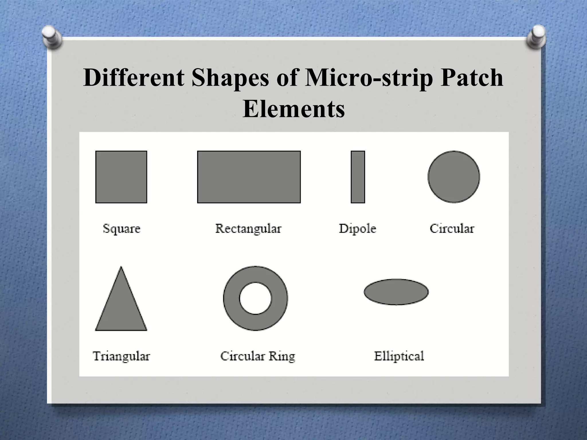
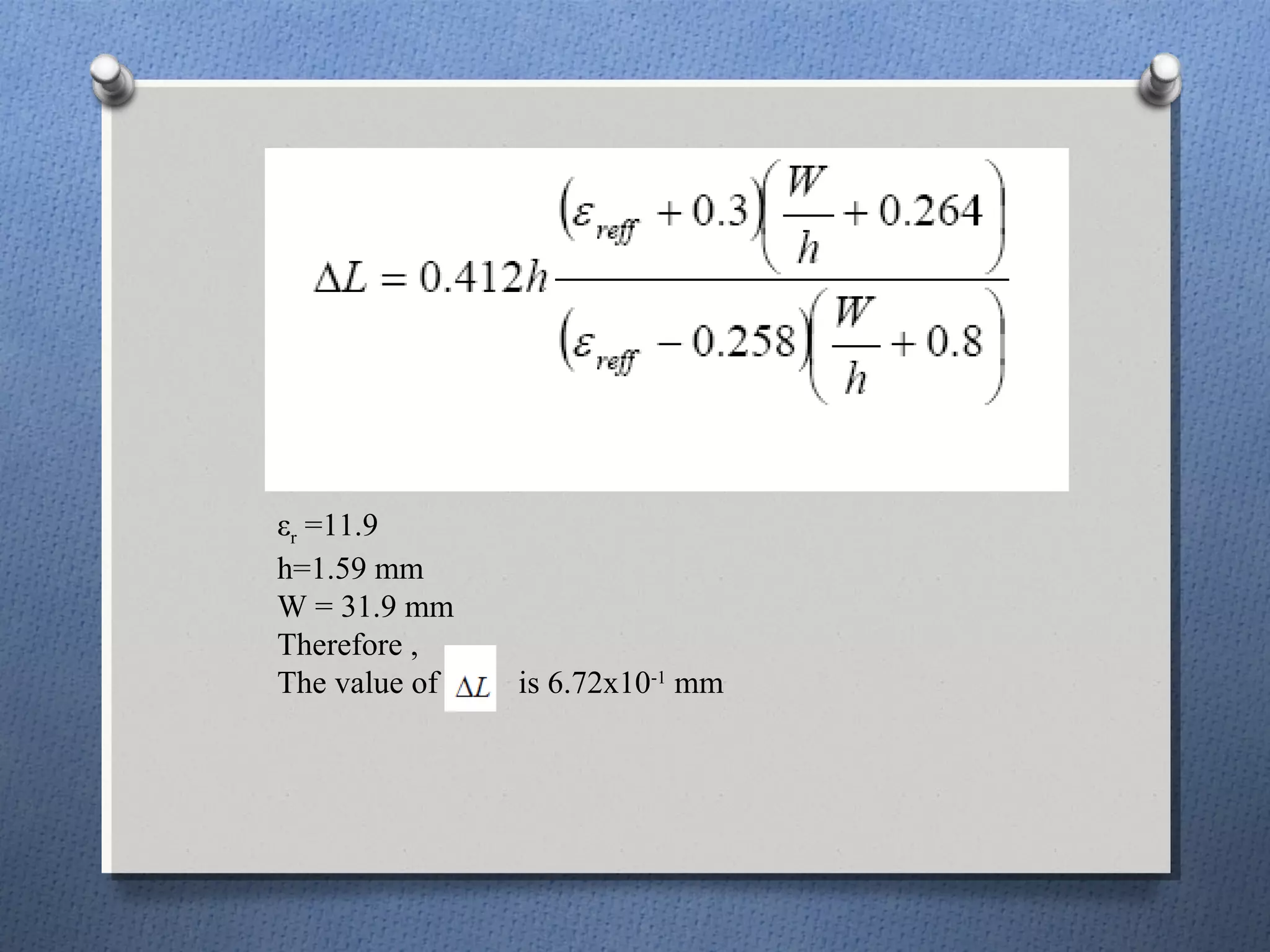
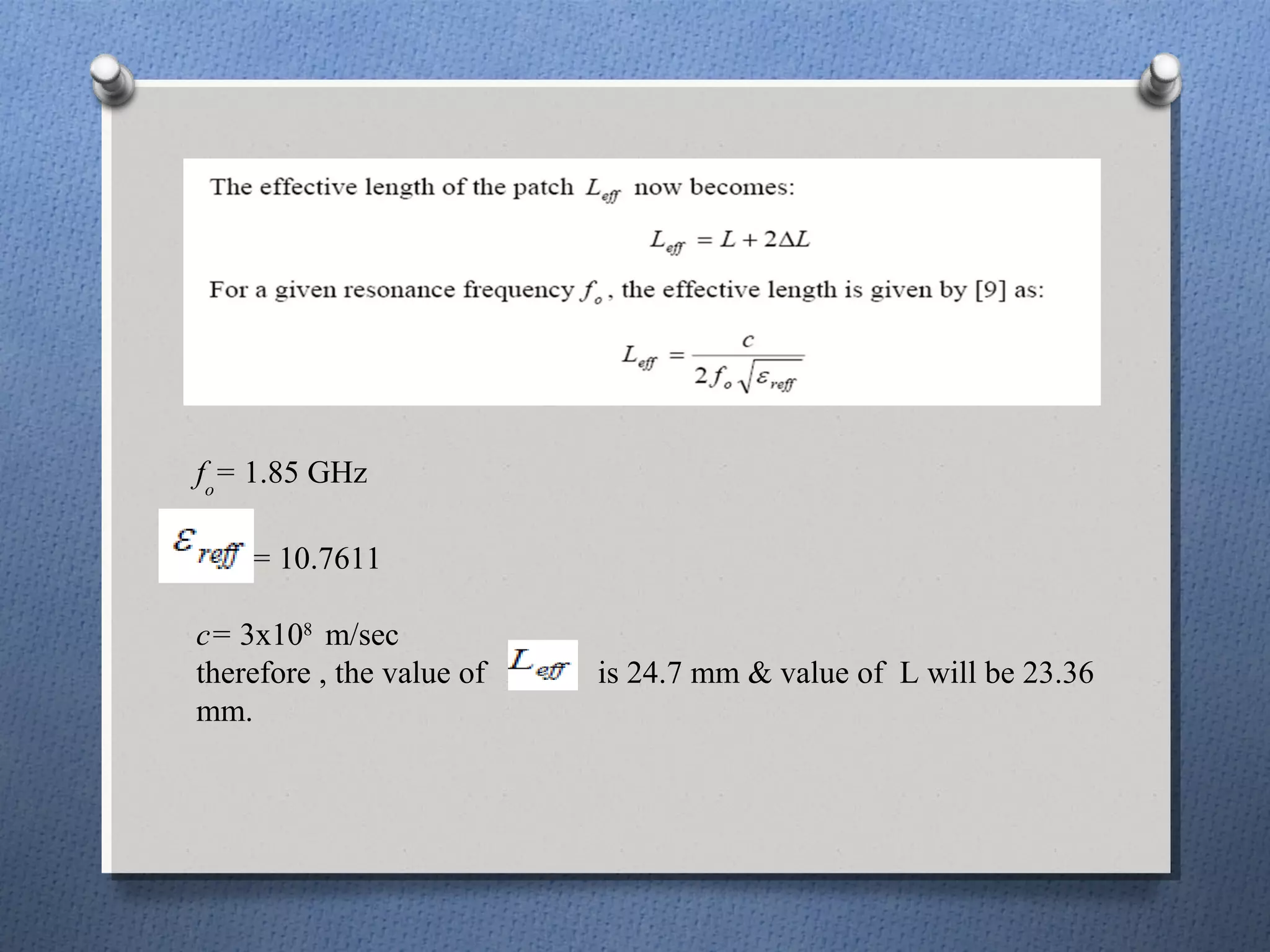
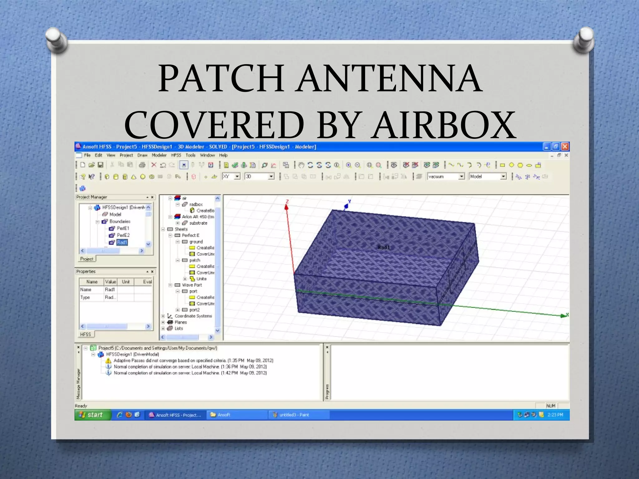
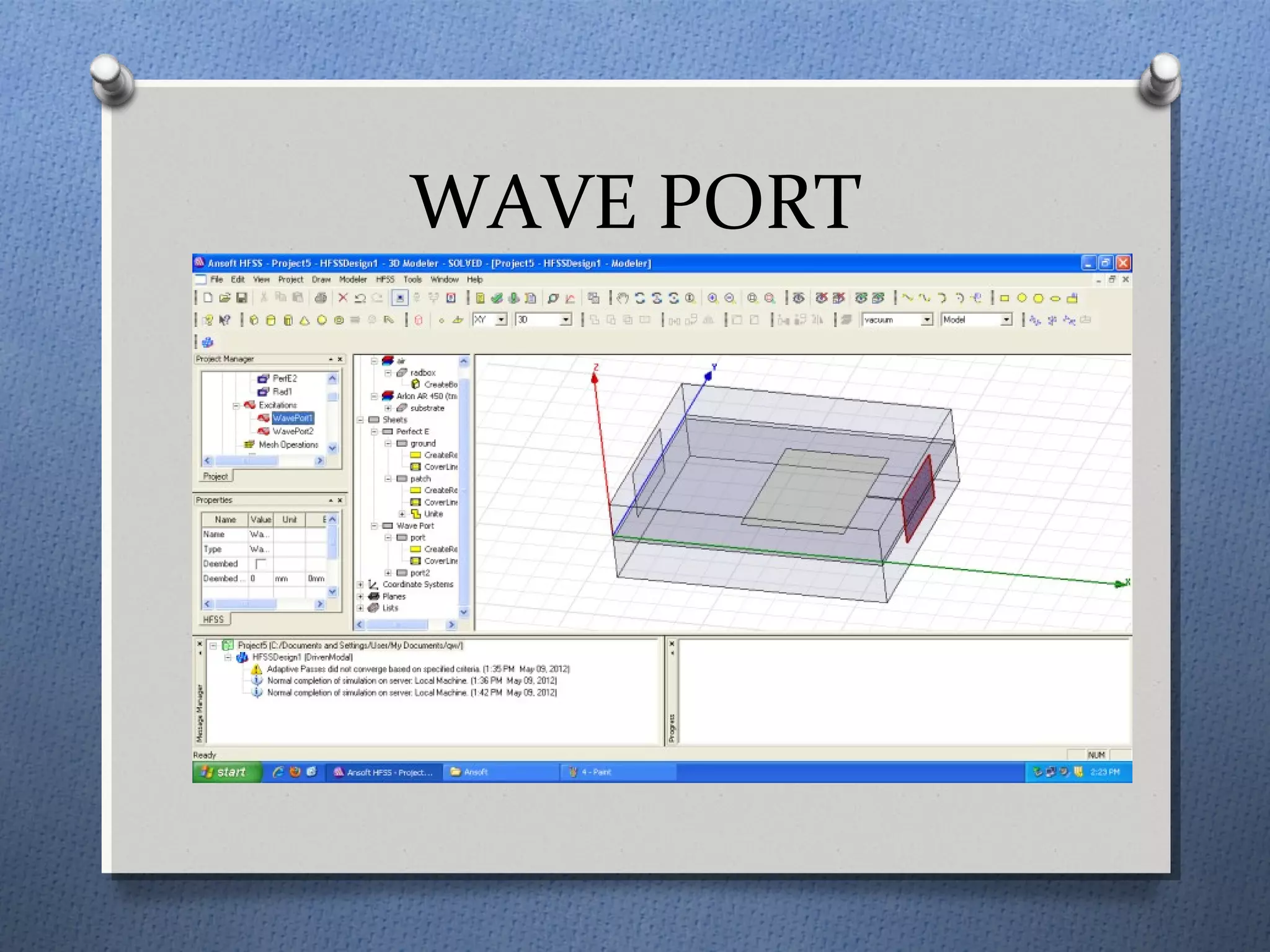
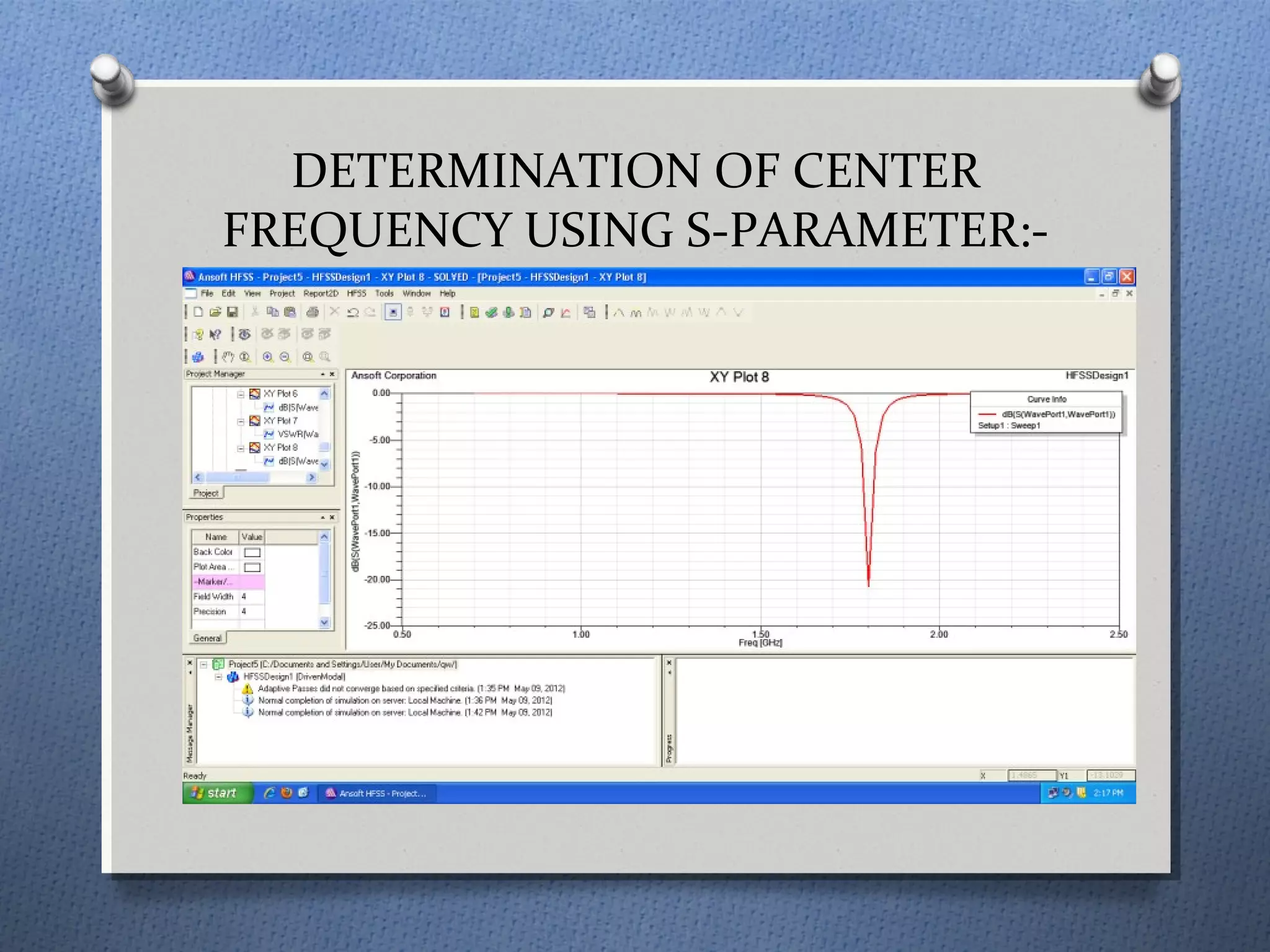
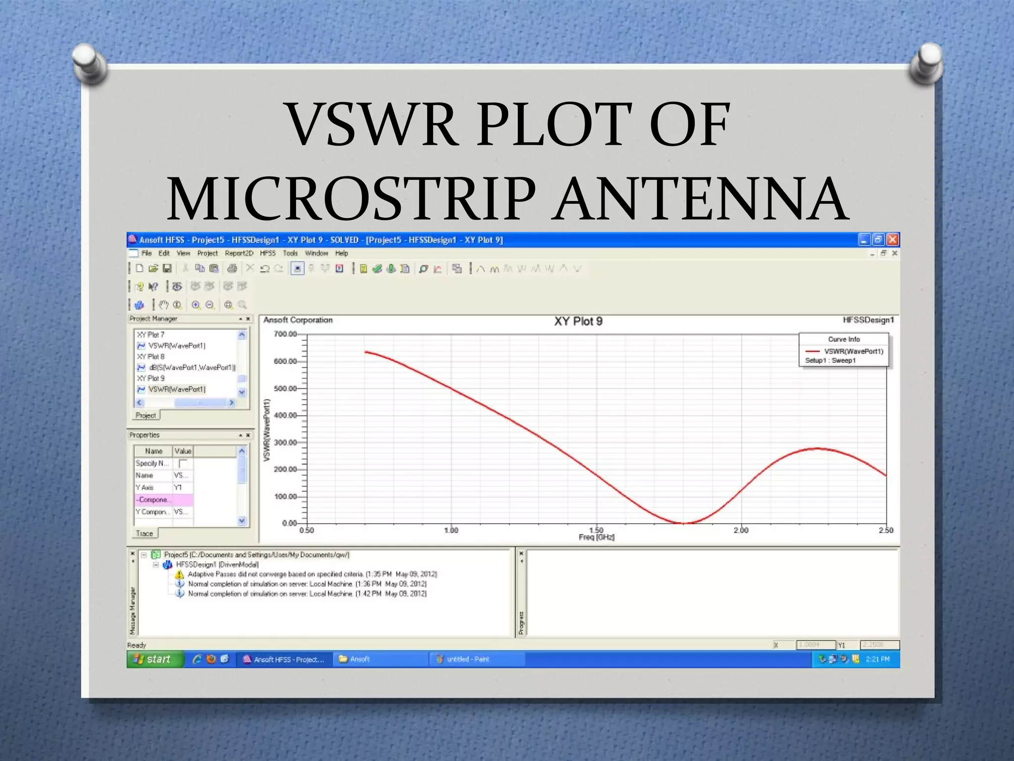
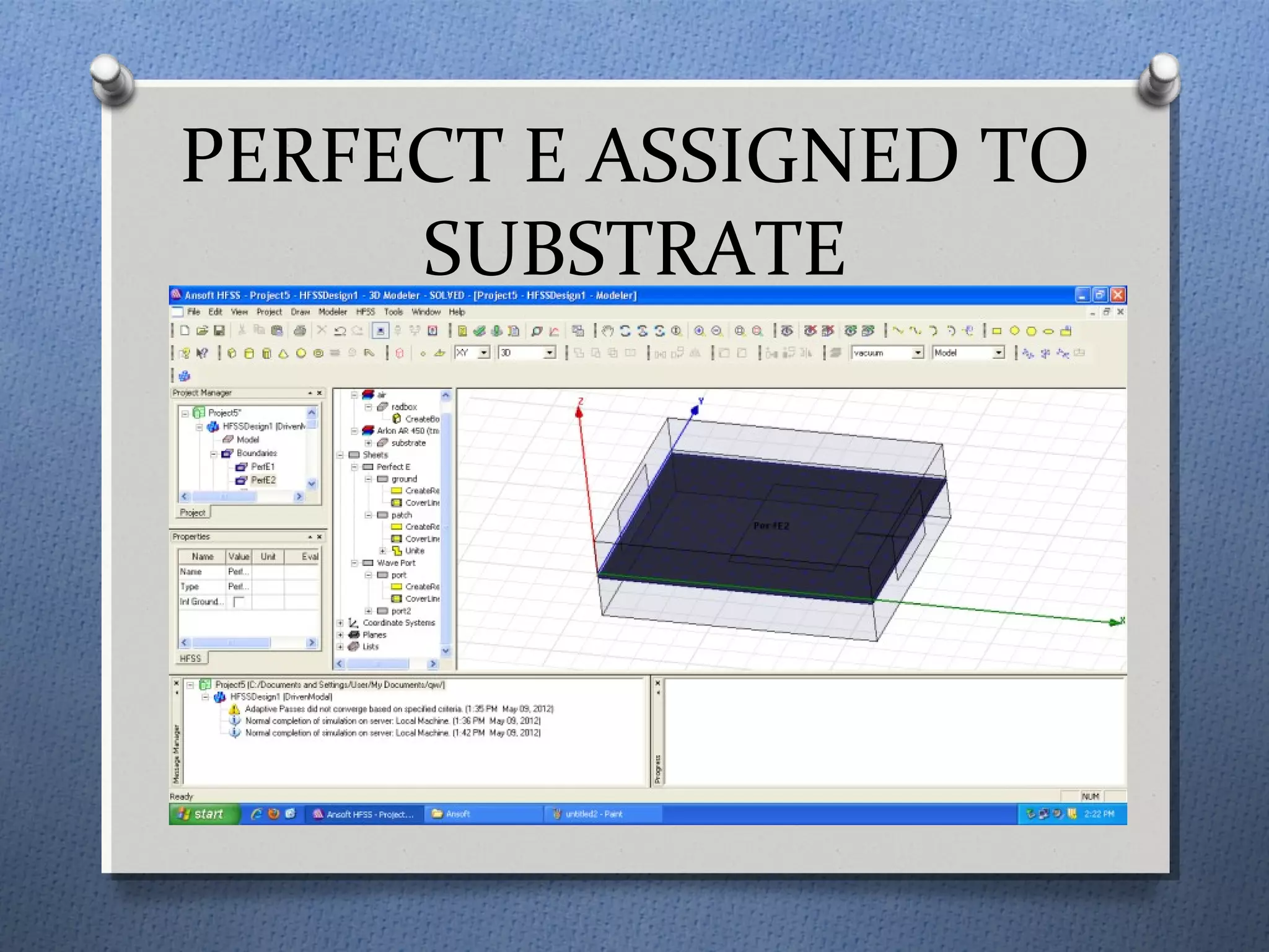
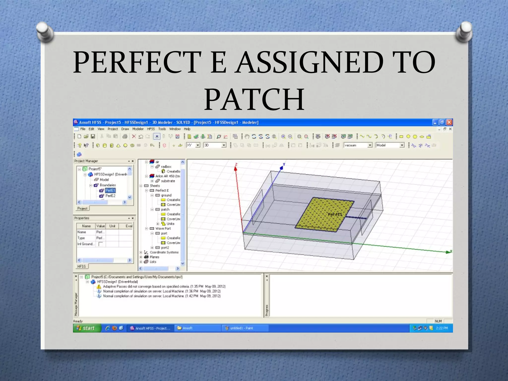


The document discusses the study and design of micro-strip patch antennas, aimed at understanding their operation principles, characteristics, and applications using HFSS software for implementation. It details the advantages and disadvantages of micro-strip antennas, various feed techniques, and specifications for design parameters. The conclusion emphasizes the potential for further design options and techniques in antenna technology.