Downloaded 127 times
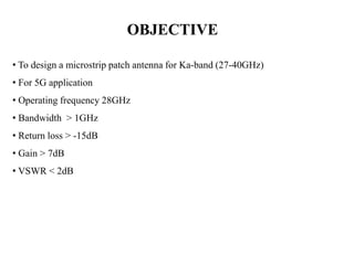

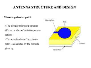
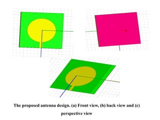
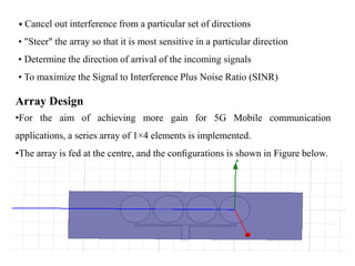
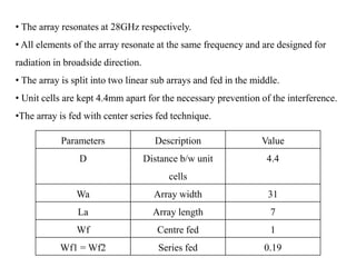
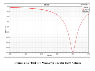
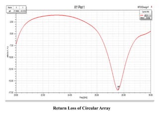
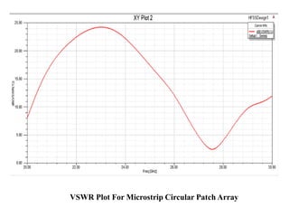
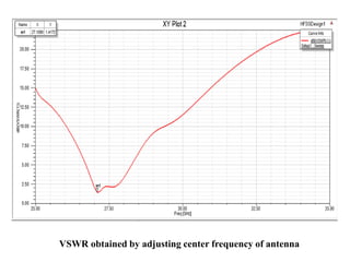
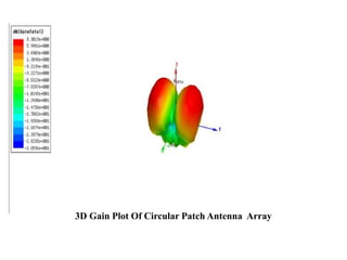


The document describes the design of a millimeter wave microstrip patch antenna for 5G applications operating at 28GHz. Key points: 1) A circular microstrip patch antenna was designed on Roger RT/duroid 5880 substrate with dielectric constant of 2.2 and thickness of 0.508mm. 2) The antenna was simulated using HFSS and achieved over 7dB gain, bandwidth over 1GHz, and return loss below -15dB at the target frequency of 28GHz. 3) To further increase gain, a 1x4 circular patch antenna array was designed and is expected to improve performance over a single element for 5G communication systems.