Downloaded 21 times


![mmL
LLeffL
L
hweffhweffhL
Leff
efffcLeff
eff
whrreff
mmw
rfocw
47.7
2
57.0
))8.0)/)((258.0/()264.0)/)((3.0(*412.0
01.0
)*0*2/(
2.7
)2/1()]^06.3/6.1(121[*)2/)14.4(()2/)14.4((
)2/1()]^/(121[*)2/)1(()2/)1((
06.3
))14.4/(2(*))9^10*5.5*2/()8^10*3((
)1/(2*)2/(
=
−=
=
+−++=
=
=
=
−+−++=
−+−++=
=
+=
+=](https://image.slidesharecdn.com/rectangularfeedlinemsafinalgroup-2-190503193657/85/Rectangular-Microstrip-Antenna-Parameter-Study-with-HFSS-7-320.jpg)
![rfocw
mmL
LLeffL
L
hweffhweffhL
Leff
efffcLeff
eff
whrreff
mmw
rfocw
mmL
LLeffL
L
)1/(2*)2/(
87.9
2
57.0
))8.0)/)((258.0/()264.0)/)((3.0(*412.0
007.0
)*0*2/(
2.7
)2/1()]^05.3/6.1(121[*)2/)14.4(()2/)14.4((
)2/1()]^/(121[*)2/)1(()2/)1((
05.3
))14.4/(2(*))9^10*16.4*2/()8^10*3((
)1/(2*)2/(
47.7
2
57.0
+=
=
−=
=
+−++=
=
=
=
−+−++=
−+−++=
=
+=
+=
=
−=
=](https://image.slidesharecdn.com/rectangularfeedlinemsafinalgroup-2-190503193657/85/Rectangular-Microstrip-Antenna-Parameter-Study-with-HFSS-12-320.jpg)
![mmL
LLeffL
L
hweffhweffhL
Leff
efffcLeff
eff
whrreff
mmw
rfocw
mmL
LLeffL
73.6
2
57.0
))8.0)/)((258.0/()264.0)/)((3.0(*412.0
01.0
)*0*2/(
2.7
)2/1()]^06.3/6.1(121[*)2/)14.4(()2/)14.4((
)2/1()]^/(121[*)2/)1(()2/)1((
05.3
))14.4/(2(*))9^10*1.6*2/()8^10*3((
)1/(2*)2/(
87.9
2
=
−=
=
+−++=
=
=
=
−+−++=
−+−++=
=
+=
+=
=
−=](https://image.slidesharecdn.com/rectangularfeedlinemsafinalgroup-2-190503193657/85/Rectangular-Microstrip-Antenna-Parameter-Study-with-HFSS-16-320.jpg)
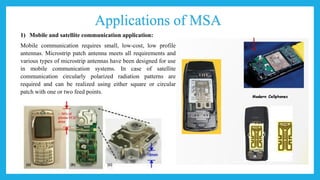
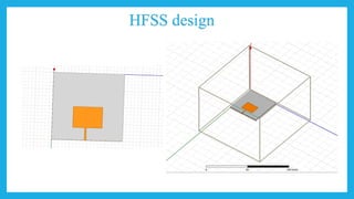
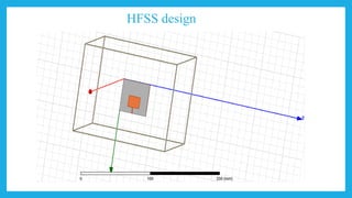
![3) Radio Frequency Identification (RFID):
RFID uses in different areas like mobile communication,
logistics, manufacturing, transportation and health care [2].
RFID system generally uses frequencies between 30 Hz and 5.8
GHz depending on its applications. Basically RFID system is a
tag or transponder and a transceiver or reader. Worldwide
Interoperability for Microwave Access (WiMax): The IEEE
802.16 standard is known as WiMax. It can reach upto 30 mile
radius theoretically and data rate 70 Mbps. MPA generates three
resonant modes at 2.7, 3.3 and 5.3 GHz and can, therefore, be
used in WiMax compliant communication equipment.](https://image.slidesharecdn.com/rectangularfeedlinemsafinalgroup-2-190503193657/85/Rectangular-Microstrip-Antenna-Parameter-Study-with-HFSS-27-320.jpg)

![References
[1] http://www.antenna-theory.com/antennas/patches/patch3.php
[2] EM-TALK Patch and Line Calculator
[3] https://www.pasternack.com/t-calculator-microstrip.aspx
[4] https://chemandy.com/calculators/microstrip-transmission-line-calculator.html](https://image.slidesharecdn.com/rectangularfeedlinemsafinalgroup-2-190503193657/85/Rectangular-Microstrip-Antenna-Parameter-Study-with-HFSS-31-320.jpg)

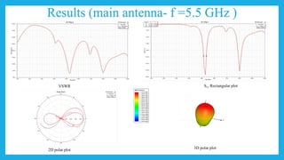
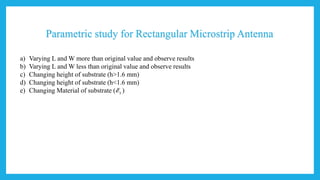
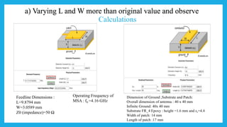
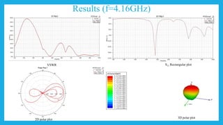
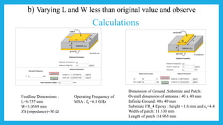
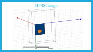
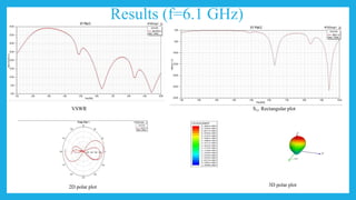
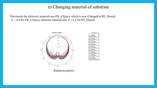
This document describes the design and parametric study of a rectangular microstrip patch antenna (MSA) using HFSS software. Key points: - MSA design involves calculating the patch width and length based on the operating frequency, substrate properties. An MSA with dimensions of 16.597mm x 12.438mm was designed to operate at 5.5GHz. - A parametric study was conducted by varying the patch dimensions and substrate properties to analyze their effect on performance. This included increasing/decreasing patch size, changing substrate height and material. - MSAs have applications in mobile/satellite communications, GPS, RFID, WiMax, radar, and telemedicine due to their low profile,


![[Deck] What's New in Spark-Iceberg Integration via DSV2.pptx](https://cdn.slidesharecdn.com/ss_thumbnails/deckwhatsnewinspark-icebergintegrationviadsv2-260210005337-25955b12-thumbnail.jpg?width=640&height=640&fit=bounds)


