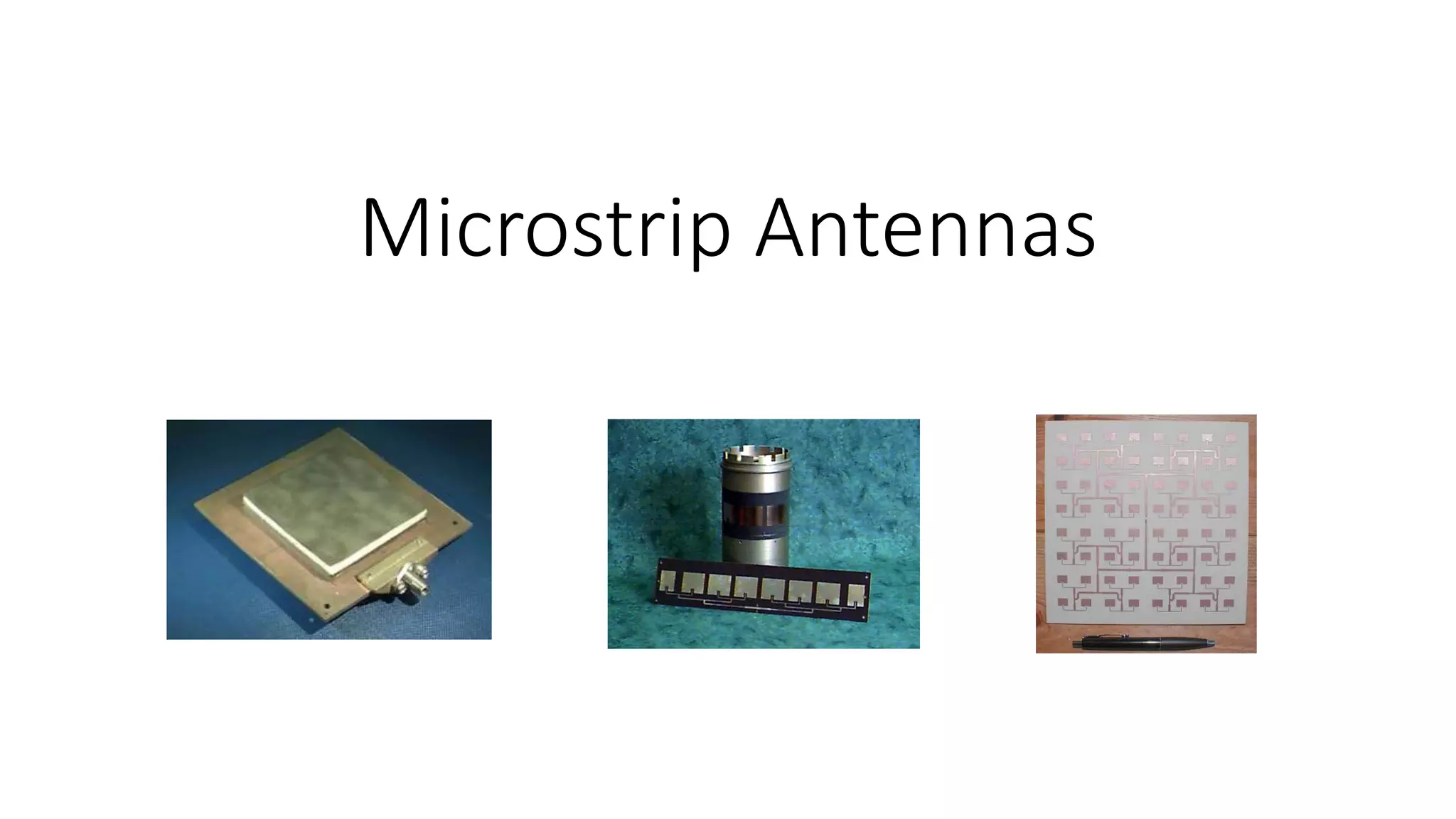
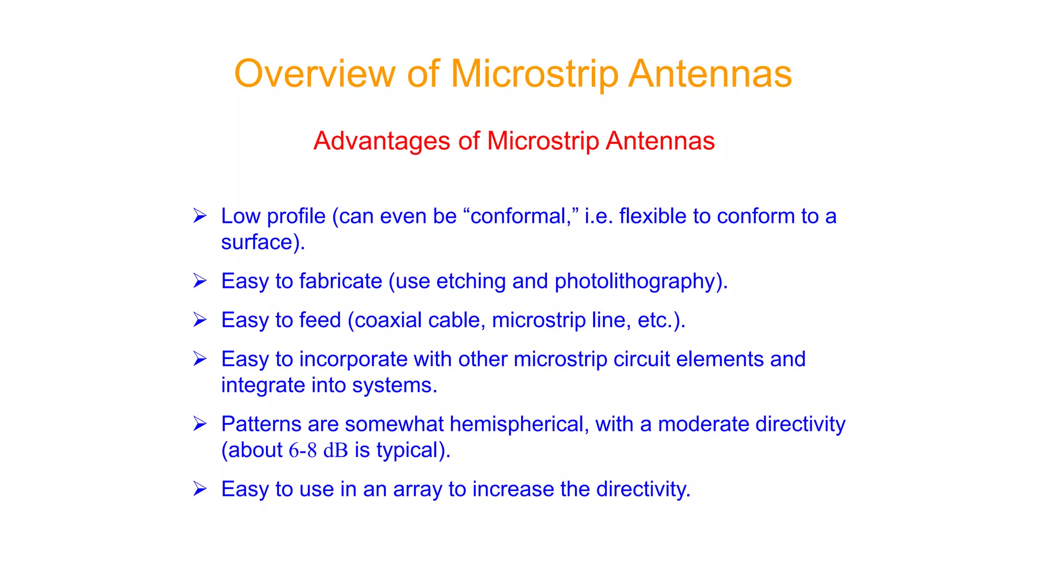
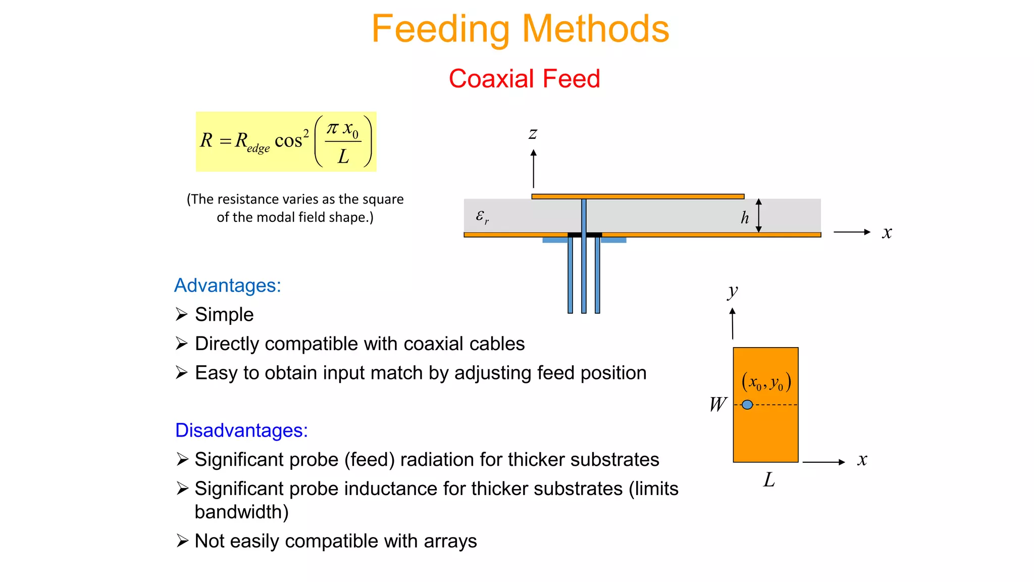
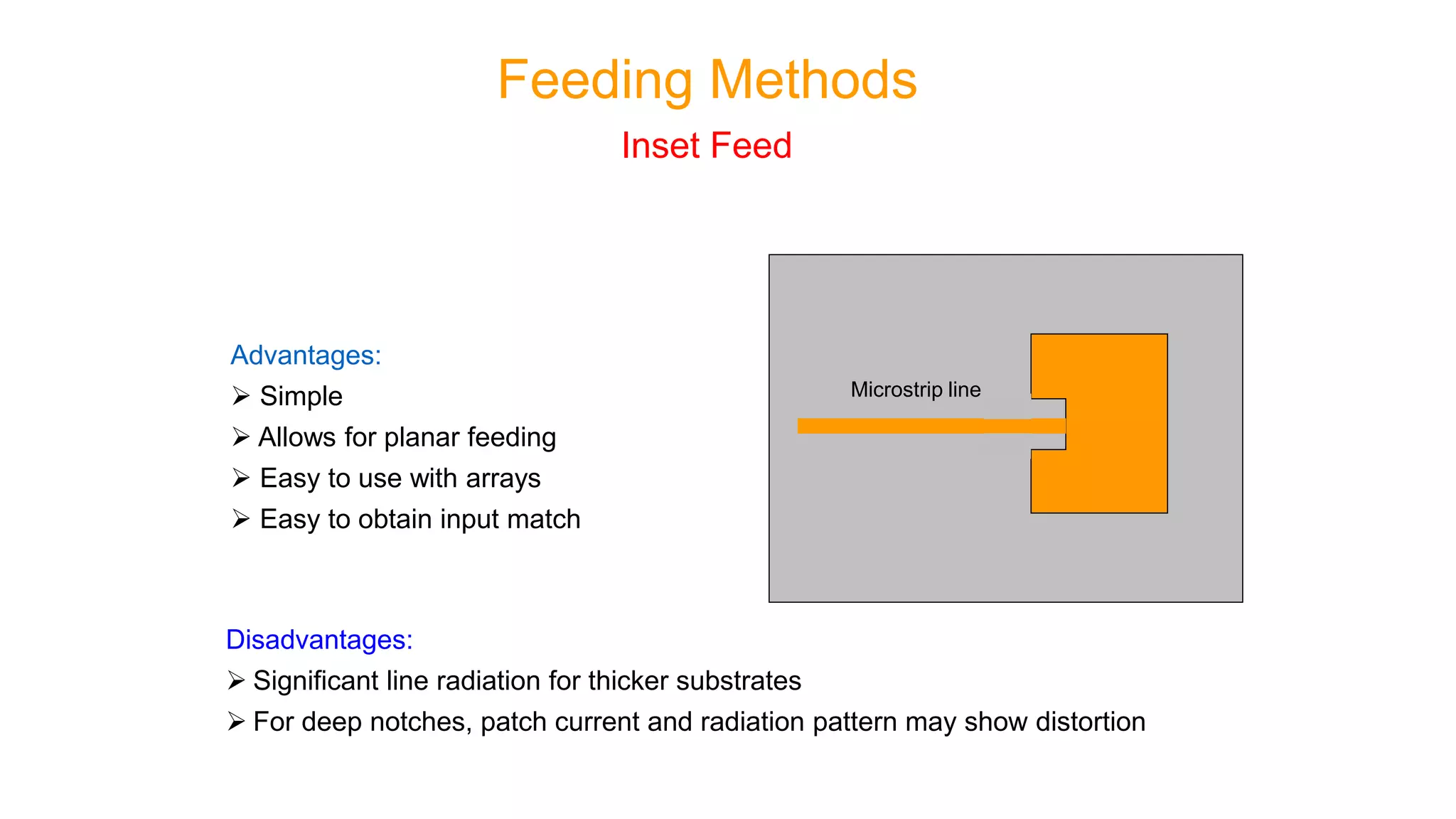
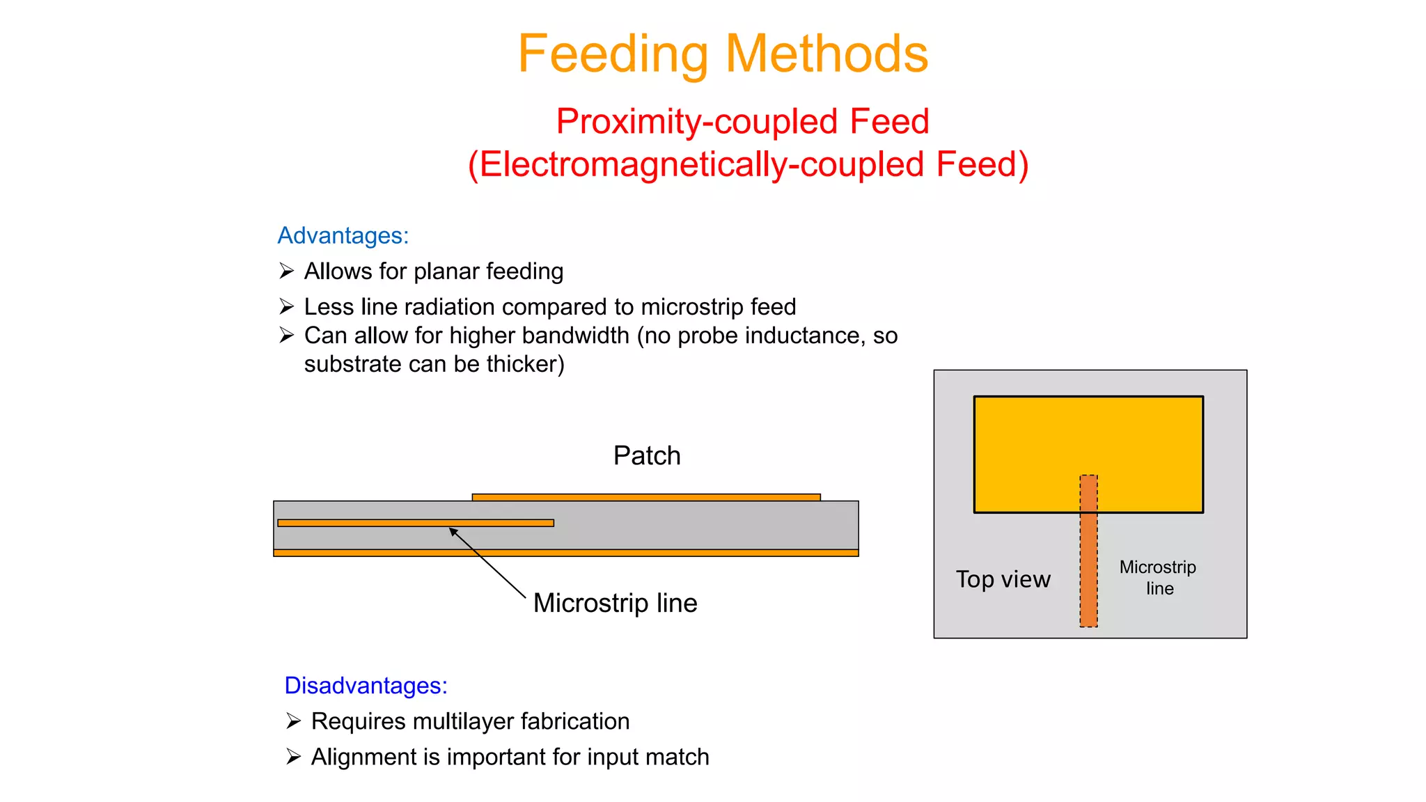
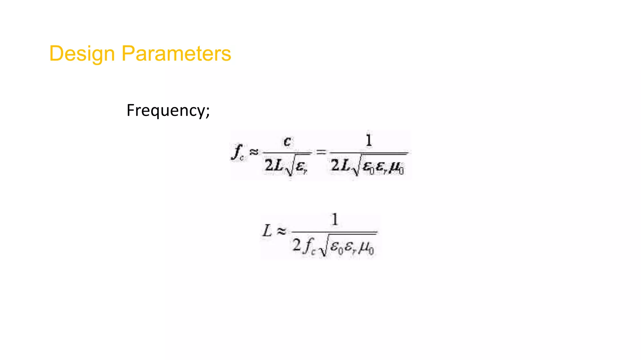
Microstrip antenna (also known as a printed antenna) usually means an antenna fabricated using microstrip techniques on a printed circuit board (PCB). They are mostly used at microwave frequencies.
2. Overview of Microstrip Antennas
• Also called “patch antennas”
One of the most useful antennas at microwave frequencies (f > 1 GHz).
It usually consists of a metal “patch” on top of a grounded dielectric substrate.
The patch may be in a variety of shapes, but rectangular and circular are the most common.
Microstrip line feed Coax feed
3. Overview of Microstrip Antennas
Common Shapes
Rectangular Square Circular
Elliptical
Annular ring
Triangular
4. (a) Top View of Patch Antenna (b) Side View of Microstrip Antenna
5. Advantages of Microstrip Antennas
Low profile (can even be “conformal,” i.e. flexible to conform to a
surface).
Easy to fabricate (use etching and photolithography).
Easy to feed (coaxial cable, microstrip line, etc.).
Easy to incorporate with other microstrip circuit elements and
integrate into systems.
Patterns are somewhat hemispherical, with a moderate directivity
(about 6-8 dB is typical).
Easy to use in an array to increase the directivity.
Overview of Microstrip Antennas
6. Disadvantages of Microstrip Antennas
Low bandwidth (but can be improved by a variety of techniques). Bandwidths of
a few percent are typical. Bandwidth is roughly proportional to the substrate
thickness and inversely proportional to the substrate permittivity.
Efficiency may be lower than with other antennas. Efficiency is limited by
conductor and dielectric losses*, and by surface-wave loss**.
Only used at microwave frequencies and above (the substrate becomes too
large at lower frequencies).
Cannot handle extremely large amounts of power (dielectric breakdown).
Overview of Microstrip Antennas
9. Wraparound Array (conformal)
(Photo courtesy of Dr. Rodney B. Waterhouse)
Overview of Microstrip Antennas
The substrate is so thin that it can be bent to “conform” to the surface.
10. Feeding Methods
Some of the more common methods for
feeding microstrip antennas are shown.
The feeding methods are illustrated for a rectangular patch,
but the principles apply for circular and other shapes as well.
11. Coaxial Feed
A feed along the centerline at
y = W/2 is the most common
(minimizes higher-order
modes and cross-pol).
x
y
L
W
Feed at (x0, y0)
Surface current
x
r h
z
Feeding Methods
12. Advantages:
Simple
Directly compatible with coaxial cables
Easy to obtain input match by adjusting feed position
Disadvantages:
Significant probe (feed) radiation for thicker substrates
Significant probe inductance for thicker substrates (limits
bandwidth)
Not easily compatible with arrays
Coaxial Feed
2 0
cosedge
x
R R
L
x
r h
z
Feeding Methods
x
y
L
W
0 0,x y
(The resistance varies as the square
of the modal field shape.)
13. Advantages:
Simple
Allows for planar feeding
Easy to use with arrays
Easy to obtain input match
Disadvantages:
Significant line radiation for thicker substrates
For deep notches, patch current and radiation pattern may show distortion
Inset Feed
Microstrip line
Feeding Methods
14. Advantages:
Allows for planar feeding
Less line radiation compared to microstrip feed
Can allow for higher bandwidth (no probe inductance, so
substrate can be thicker)
Disadvantages:
Requires multilayer fabrication
Alignment is important for input match
Patch
Microstrip line
Feeding Methods
Proximity-coupled Feed
(Electromagnetically-coupled Feed)
Top view
Microstrip
line
15. Advantages:
Allows for planar feeding
Can allow for a match even with high edge impedances, where a notch
might be too large (e.g., when using high permittivity)
Disadvantages:
Requires accurate gap fabrication
Requires full-wave design
Patch
Microstrip line
Gap
Feeding Methods
Gap-coupled Feed
Top view
Microstrip
line
Patch
16. Advantages:
Allows for planar feeding
Feed-line radiation is isolated from patch radiation
Higher bandwidth is possible since probe inductance is
eliminated (allowing for a thick substrate), and also a
double-resonance can be created
Allows for use of different substrates to optimize
antenna and feed-circuit performance
Disadvantages:
Requires multilayer fabrication
Alignment is important for input match
Patch
Microstrip line
Slot
Feeding Methods
Aperture-coupled Patch (ACP)
Top view
Slot
Microstrip
line
17. Fringing Effect
• The fringing fields around the antenna can help explain why the microstrip
antenna radiates.
20. Design Parameters
Bandwidth;
The height of the substrate h also controls the bandwidth, increasing the height increases the bandwidth.
Increasing the height also increases the efficiency of the antenna.
Microstrip or patch antennas are becoming increasingly useful because they can be printed directly onto a circuit board.
Microstrip antennas are becoming very widespread within the mobile phone market.
Consider the microstrip antenna shown in Figure, fed by a microstrip transmission line. The patch antenna, microstrip transmission line and ground plane are made of high conductivity metal (typically copper).
The patch is of length L, width W, and sitting on top of a substrate (some dielectric circuit board) of thickness h with permittivity .
The thickness of the ground plane or of the microstrip is not critically important.
Typically the height h is much smaller than the wavelength of operation, but should not be much smaller than 0.025 of a wavelength (1/40th of a wavelength) or the antenna efficiency will be degraded.
* Conductor and dielectric losses become more severe for thinner substrates.
** Surface-wave losses become more severe for thicker substrates (unless air or foam is used).
It is the fringing fields that are responsible for the radiation.Note that the fringing fields near the surface of the patch antenna are both in the +y direction. Hence, the fringingE-fields on the edge of the microstrip antenna add up in phase and produce the radiation of the microstrip antenna.
All of the parameters in a rectangular patch antenna design (L, W, h, permittivity) control the properties of the antenna. As such, this page gives a general idea of how the parameters affect performance, in order to understand the design process.
First, the length of the patch L controls the resonant frequency as seen here. This is true in general, even for more complicated microstrip antennas that weave around - the length of the longest path on the microstrip controls the lowest frequency of operation. Equation (1) below gives the relationship between the resonant frequency and the patch length:
The permittivity of the substrate controls the fringing fields - lower permittivities have wider fringes and therefore better radiation. Decreasing the permittivity also increases the antenna's bandwidth. The efficiency is also increased with a lower value for the permittivity. The impedance of the antenna increases with higher permittivities.
Higher values of permittivity allow a "shrinking" of the patch antenna. Particularly in cell phones, the designers are given very little space and want the antenna to be a half-wavelength long. One technique is to use a substrate with a very high permittivity.
The fact that increasing the height of a patch antenna increases its bandwidth can be understood by recalling the general rule that "an antenna occupying more space in a spherical volume will have a wider bandwidth". This is the same principle that applies when noting that increasing the thickness of a dipole antenna increases its bandwidth.
Increasing the height does induce surface waves that travel within the substrate (which is undesired radiation and may couple to other components).