The document describes the design and simulation of a basic half-wave dipole antenna. Key points:
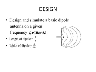
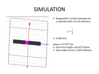
1) The aim is to design a dipole antenna for a given frequency of 3.3 GHz and study the effects of varying the dielectric constant and substrate thickness on the radiation properties and frequency response.
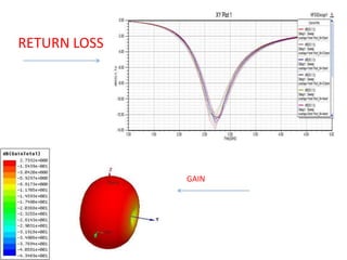
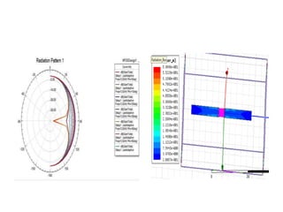
2) Important antenna characteristics to consider include radiation patterns, gain, and frequency response.
3) The half-wave dipole antenna is designed with each arm measuring 22.725mm to operate at the target frequency, and each arm width is 4.545mm.
4) Simulation shows the antenna operates at 2.8GHz with a return loss of -14.50dB and gain of