Downloaded 162 times

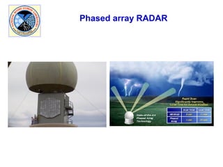
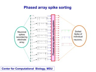
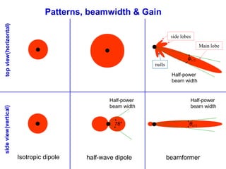
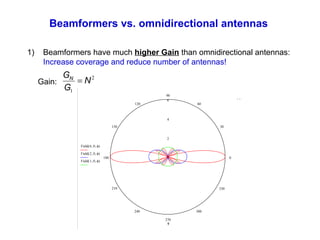
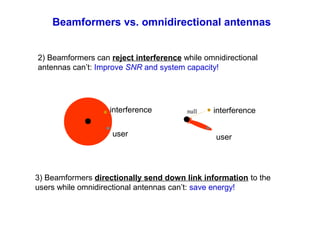
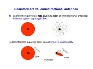
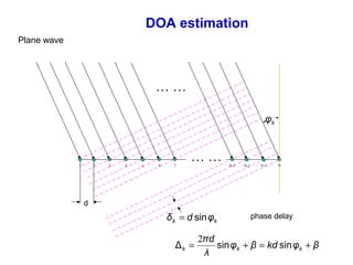
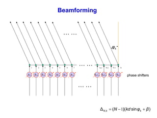
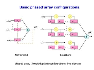

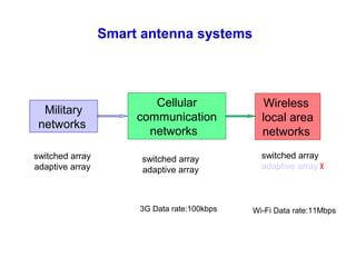
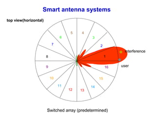
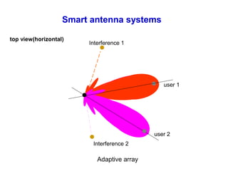
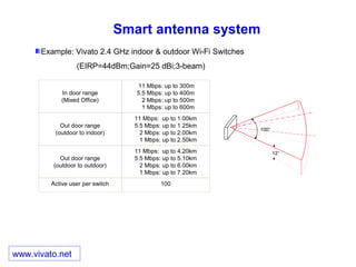
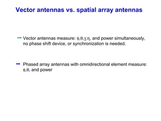

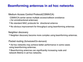
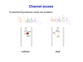

The document discusses beamforming antennas and their applications. It begins by outlining beamforming concepts and configurations like phased arrays and adaptive arrays. It then discusses applications of beamforming antennas in areas like radar, sonar, communications and imaging. Specific examples covered include phased array radar, neuronal spike sorting, and smart antenna systems for wireless networks. Vector antennas and their advantages over phased arrays are also summarized. Finally, the document discusses potential uses and challenges of beamforming antennas for wireless ad hoc networks.