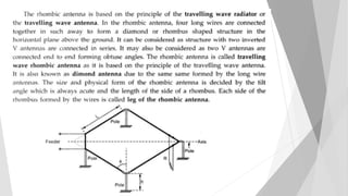
Traveling Wave Antenna
Antenna Theory
Prepared by
Abdelaziz Said
Electrical Engineering
Department
New Cairo Academy
- Traveling wave antenna is non-resonant
type antenna or aperiodic antenna
Definitions
- The antenna in which the standing wave
does not exist along the length of the
antenna is called traveling wave antenna
Q1
What is the difference between standing
wave and traveling wave ?
Q2
What is the difference between resonant
and non-resonant antenna ?
1- Long Wire Antenna
An antenna is usually classified as a long wire
antenna if it is a very straight conductor with a
length from one to many wavelengths
Antenna Height (h)
Total field radiated by the wire
 It is found by multiplying the field radiated by the wire in free space
by the array factor of a two-element array
 the wave travels along the wire from the source toward the load, it
continuously leaks energy (attenuation coefficient)
Field radiated in free space
Radiated by long wire to free space
Current distribution along structure
 If = aˆz Iz (z΄) e− γ(z΄)z΄ = az I0 e−[α(z΄)+jkz(z΄)]z΄
 By approx. : If = aˆz Iz (z΄) e− jKz Z΄ = az I0 e− jKz Z΄
 K =
𝐾𝑧
𝐾
=
λ
λ𝑔
it is evident that the power distribution of a wire antenna of length l is a multi lobe
pattern whose number of lobes depends upon its length.
To calculate Peaks of lopes
For angles the peaks occur
To find nulls
Angles where the nulls occurs
Total radiated power
Radiation resistance
Directivity
Design long wires
Amplitude pattern , maxima and nulls
Input Impedance
 Provides strong Minor Lobes
Disadvantages
 Easy to Construct
 More Cheap than V antenna
 More simple
 Larger Bandwidth
 Input impedance is High
Applications
 Commercial applications
 Mellatry applications
 For RF communications
 Microwave communications
 Long Closed places likes tunnels
2- V Antenna
The V antenna is made up of two wire antenna which are
arranged in the form of the horizontal V and it is fed at the
apex by the transmission feed line.
For some applications a single long-wire antenna is not very
practical because
(1) its directivity may be low.
(2) its side lobes may be high.
These and other drawbacks of single long-wire antennas can be
overcome by utilizing an array of wires, One very practical array of
long wires is the V
 There are two Types:
 Resonant V antenna
 Non-Resonant V antenna
Most V antennas are symmetrical (θ1 =θ2 =θ0 and l1 =l2 =l).
Also V antennas can be designed to have unidirectional or
bidirectional radiation patterns, as shown in Figures
 Easy to Construct
 Cheap
 Provides strong Minor Lobes
 On Light Aircraft
 Military appliances
 Commercial appliances
3- Rhombic Antenna
Two V antennas can be connected at their open ends to form a
diamond or rhombic antenna, The antenna is usually terminated
at one end in a resistor, usually about 600–800 ohms, in order to
reduce if not eliminate reflections
- Radiation Pattern
 Unidirectional Pattern
 Lobes = 2 to 8 long
 Directivity : 20 to 90
 Power Gain : 50 to 60
 β value = 17 to 24 degree 
Assignment

- Design of Rhombic antenna
 The tilt angle ()
 The leg length (L)
 The height above the ground (h)
 Two designs
(a) Alignment design
(b) Maximum output design
- Design of Rhombic antenna
(a) Alignment design
h is chosen that max of the main lobe coincides with the desired angle of elevation 


sin4
h


2
sin
37.0
L   90
(b) Maximum field intensity design
h is chosen that max filed intensity is obtained at the desired elevation angle 
mh


sin4

mL


2
sin2
   90
 Highly directional
 Simple & cheap
 Needs larger space for installation
 Efficiency is Low
 HF transmission & reception
Thank you…

Traveling Wave Antenna

  • 1.
    Traveling Wave Antenna AntennaTheory Prepared by Abdelaziz Said Electrical Engineering Department New Cairo Academy
  • 2.
    - Traveling waveantenna is non-resonant type antenna or aperiodic antenna Definitions - The antenna in which the standing wave does not exist along the length of the antenna is called traveling wave antenna
  • 3.
    Q1 What is thedifference between standing wave and traveling wave ? Q2 What is the difference between resonant and non-resonant antenna ?
  • 5.
    1- Long WireAntenna An antenna is usually classified as a long wire antenna if it is a very straight conductor with a length from one to many wavelengths Antenna Height (h)
  • 6.
    Total field radiatedby the wire  It is found by multiplying the field radiated by the wire in free space by the array factor of a two-element array  the wave travels along the wire from the source toward the load, it continuously leaks energy (attenuation coefficient) Field radiated in free space Radiated by long wire to free space
  • 7.
    Current distribution alongstructure  If = aˆz Iz (z΄) e− γ(z΄)z΄ = az I0 e−[α(z΄)+jkz(z΄)]z΄  By approx. : If = aˆz Iz (z΄) e− jKz Z΄ = az I0 e− jKz Z΄  K = 𝐾𝑧 𝐾 = λ λ𝑔
  • 8.
    it is evidentthat the power distribution of a wire antenna of length l is a multi lobe pattern whose number of lobes depends upon its length. To calculate Peaks of lopes
  • 9.
    For angles thepeaks occur To find nulls Angles where the nulls occurs
  • 10.
    Total radiated power Radiationresistance Directivity
  • 12.
    Design long wires Amplitudepattern , maxima and nulls
  • 13.
  • 14.
     Provides strongMinor Lobes Disadvantages  Easy to Construct  More Cheap than V antenna  More simple  Larger Bandwidth  Input impedance is High
  • 15.
    Applications  Commercial applications Mellatry applications  For RF communications  Microwave communications  Long Closed places likes tunnels
  • 16.
    2- V Antenna TheV antenna is made up of two wire antenna which are arranged in the form of the horizontal V and it is fed at the apex by the transmission feed line. For some applications a single long-wire antenna is not very practical because (1) its directivity may be low. (2) its side lobes may be high. These and other drawbacks of single long-wire antennas can be overcome by utilizing an array of wires, One very practical array of long wires is the V
  • 17.
     There aretwo Types:  Resonant V antenna  Non-Resonant V antenna
  • 20.
    Most V antennasare symmetrical (θ1 =θ2 =θ0 and l1 =l2 =l). Also V antennas can be designed to have unidirectional or bidirectional radiation patterns, as shown in Figures
  • 23.
     Easy toConstruct  Cheap  Provides strong Minor Lobes  On Light Aircraft  Military appliances  Commercial appliances
  • 24.
    3- Rhombic Antenna TwoV antennas can be connected at their open ends to form a diamond or rhombic antenna, The antenna is usually terminated at one end in a resistor, usually about 600–800 ohms, in order to reduce if not eliminate reflections
  • 26.
    - Radiation Pattern Unidirectional Pattern  Lobes = 2 to 8 long  Directivity : 20 to 90  Power Gain : 50 to 60  β value = 17 to 24 degree 
  • 27.
  • 28.
     The tiltangle ()  The leg length (L)  The height above the ground (h)  Two designs (a) Alignment design (b) Maximum output design - Design of Rhombic antenna
  • 30.
    (a) Alignment design his chosen that max of the main lobe coincides with the desired angle of elevation    sin4 h   2 sin 37.0 L   90
  • 31.
    (b) Maximum fieldintensity design h is chosen that max filed intensity is obtained at the desired elevation angle  mh   sin4  mL   2 sin2    90
  • 32.
     Highly directional Simple & cheap  Needs larger space for installation  Efficiency is Low  HF transmission & reception
  • 33.