Microstrip antennas or patch antennas are popular for their attractive features such as low profile,
low weight, low cost, ease of fabrication and integration with RF devices. Micro strip antennas have been found
favorable because they are inexpensive to manufacture and compatible with monolithic microwave integrated
circuit designs (MMIC). They are usually employed at UHF and higher frequencies because the size of the
antenna is directly tied to the wavelength at the resonance frequency. A Microstrip or patch antenna is a
narrowband, wide-beam antenna fabricated by etching the antenna element pattern in metal trace bonded to an
insulating dielectric substrate with a continuous metal layer bonded to the opposite side of the substrate which
forms a ground plane. The most commonly employed microstrip antenna is a rectangular patch.
The major disadvantages of Microstrip antennas are lower gain and very narrow bandwidth. Microstrip patch
antennas have some drawbacks of low efficiency, narrow bandwidth (3-6%) of the central frequency. Millimeter
wave technology being an emerging area is still much undeveloped. As micro strip antennas have found wide
variety of application areas, a number of techniques are evolved to improve its limited bandwidth. A good
approach to improve the bandwidth is increasing the thickness of substrate supporting the micro strip patch.
However problems exist on the ability to effectively feed the patch on a thick substrate and the radiation
efficiency can degrade with increasing substrate thickness. A substantial research needs to be done in this area
as its applications are numerous. The radiation patterns and S11 performance are used for the analysis of the
different configurations. In the present endeavor a rectangular patch antenna is designed on thick substrate and simulated using MATLAB software and configuration on different dielectric susbstrates was used .
Study On The Improvement Of Bandwidth Of A Rectangular Microstrip Patch Antenna
1. IOSR Journal of Electronics and Communication Engineering (IOSR-JECE)
e-ISSN: 2278-2834,p- ISSN: 2278-8735.Volume 5, Issue 5 (Mar. - Apr. 2013), PP 16-22
www.iosrjournals.org
www.iosrjournals.org 16 | Page
Study On The Improvement Of Bandwidth Of A Rectangular
Microstrip Patch Antenna
P.Bharath1
, C.Dharmaraj2
, B.Srinu3
1
(M.Tech, II year,Department of E.C.E, Gitam Institute of Technology/GITAM University , INDIA)
2
(Professor-Vice Principal, Department of E.C.E, Gitam Institute of Technology/GITAM University , INDIA)
3
(Assistant Professor, Department of E.C.E, Gitam Institute of Technology/GITAM University , INDIA)
Abstract : Microstrip antennas or patch antennas are popular for their attractive features such as low profile,
low weight, low cost, ease of fabrication and integration with RF devices. Micro strip antennas have been found
favorable because they are inexpensive to manufacture and compatible with monolithic microwave integrated
circuit designs (MMIC). They are usually employed at UHF and higher frequencies because the size of the
antenna is directly tied to the wavelength at the resonance frequency. A Microstrip or patch antenna is a
narrowband, wide-beam antenna fabricated by etching the antenna element pattern in metal trace bonded to an
insulating dielectric substrate with a continuous metal layer bonded to the opposite side of the substrate which
forms a ground plane. The most commonly employed microstrip antenna is a rectangular patch.
The major disadvantages of Microstrip antennas are lower gain and very narrow bandwidth. Microstrip patch
antennas have some drawbacks of low efficiency, narrow bandwidth (3-6%) of the central frequency. Millimeter
wave technology being an emerging area is still much undeveloped. As micro strip antennas have found wide
variety of application areas, a number of techniques are evolved to improve its limited bandwidth. A good
approach to improve the bandwidth is increasing the thickness of substrate supporting the micro strip patch.
However problems exist on the ability to effectively feed the patch on a thick substrate and the radiation
efficiency can degrade with increasing substrate thickness. A substantial research needs to be done in this area
as its applications are numerous. The radiation patterns and S11 performance are used for the analysis of the
different configurations. In the present endeavor a rectangular patch antenna is designed on thick substrate and
simulated using MATLAB software and configuration on different dielectric susbstrates was used .
Keywords - bandwidth, dielectric constant, Microstrip antennas, substrate thickness .
I. INTRODUCTION
A microstrip patch antenna has the advantages of low cost, light weight, and low profile planner
configuration. However, they suffer from the disadvantage of low operating bandwidth. The use of transmission
line method to analyze the rectangular micro strip antenna (rmpa) can be done in this work. The most commonly
employed microstrip antenna is a rectangular patch. The rectangular patch antenna is approximately a one-half
wavelength long section of rectangular microstrip transmission line. The resonant length of the antenna is a bit
shorter because of the extended electric fringing field which increases the electrical length of the antenna
slightly. The previous model of the microstrip antenna is a section of microstrip transmission line with
equivalent loads on either end to represent the radiation loss. The dielectric filling of a microstrip antenna
affects both its radiation pattern and impedance bandwidth as the increase in dielectric constant of the substrate
results in decrease of the antenna bandwidth which increases the factor of the antenna and therefore decreases
the impedance bandwidth. Larger Bandwidth can be achieved by loading slots within the patch of the antenna
and with different shapes, arrangements and sizes the effect of this techniques on increasing the bandwidth is
more than using the other techniques to realize compact msas there are several techniques, such as higher
dielectric constant substrate, a slot cut inside the patch for broader bw, thicker and lower dielectric constant
substrates and single slot cut.
2. Study On The Improvement Of Bandwidth Of A Rectangular Microstrip Patch Antenna
www.iosrjournals.org 17 | Page
II. RECTANGULAR MICROSTRIP PATCH ANTENNA DESIGN CONSIDERATIONS
Fig 2.1 : Structure of rectangular microstrip patch antenna
In this model the MSA can be represented by two slots of width (W) and height (h) separated by transmission
line of length (L). The width of the patch can be calculated from the following equation.
The effective dielectric constant (εeff) is less than (εr) because the fringing field around the periphery of the
patch is not confined to the dielectric speared in the air also.
For TM10 Mode the length of the patch must be less than (λ /2) .This difference in the length (ΔL) which is
given empirically by.
Where c=speed of light, Leff = effective length. Fr=resonance frequency, εeff = effective dielectric
constant.
L =
DESIGN CONSIDERATION
Step one
Substrate selection
The first step in the design is to choose a suitable dielectric substrate of appropriate thickness h. A
thicker substrate, serves as mechanically strong but it will increase the radiated power, reduce the conductor
loss and improve impedance bandwidth.
Step two
Width and length parameters
A larger patch width increases the power radiated and thus gives decreased resonant resistance,
increased BW and increased radiation efficiency. It is good to choose patch width W greater than patch length.
The general consideration is 1 < W/ L < 2 .
In case of microstrip antenna, it is proportional to its quality factor Q and given by as:
BW =
The percentage bandwidth of the rectangular patch micro strip antenna in terms of patch dimensions
and substrates parameters is given as follows .
BW % =
A = 180 for 0.045
3. Study On The Improvement Of Bandwidth Of A Rectangular Microstrip Patch Antenna
www.iosrjournals.org 18 | Page
A = 200 for 0.045 0.075
A = 220 for 0.075
Where h is the substrate thickness, λ
o
is the wavelength in the substrate, εr being the dielectric constant
of substrate, W, L is the width and length of patch dimension.. The WIFI applications use the frequency range
from (2-3 GHz)
III. BANDWIDTH ENHANCEMENT TECHNIQUES
There are many ways to improve the bandwidth which is mainly controlled by the characteristics of the parallel
plate transmission line. The bandwidth can be increased by :
1. A good approach to improve the bandwidth is increasing the thickness of substrate supporting the micro
strip patch.
2. By the use of high dielectric constants substrate so that the physical dimensions of the parallel plate line
are decreased
3. By increasing the inductance of the microstrip by cutting holes or slot in it.
4. By adding reactive component to reduce the VSWR.
The first approach done is to design a rectangular patch antenna with an operating frequency of 2.4 GHz as it
has low return loss at that frequency and taking FR4 as the dielectric substrate which has a dielectric constant of
4 and by varying the thickness of the substrate from 2mm,3mm,4mm the bandwidth variations are observed to
be increasing and the simulation is done using MATLAB and radiation patterns are observed along with
bandwidth . For all the three configurations the width of the patch is maintained constant and the length of the
patch changes for the three configurations .The performance (BW, radiation patterns) was studied and analyzed
for the simulated configurations.
The second approach done is to design a rectangular patch antenna with different dielectric substrates
having different dielectric constants at an operating frequency of 2 GHz and the thickness of the substrate is
constant for all cases of 1.5 mm. Here, three different dielectric materials are chosen they are duroid 5880, FR4
and alumina whose dielectric constants are 2.2, 4, and 9.8 respectively. The simulations are carried out using
MATLAB and different results on antenna parameters were noted. Also patch length and width vs. frequency is
analyzed.
IV. SIMULATION RESULTS
The simulation results for the first work of designing rectangular patch antennas with different
thickness of substrate are shown as below :
0.2
0.4
0.6
0.8
1
30
210
60
240
90
270
120
300
150
330
180 0
Radiation plot of E and H plane patterns
H plane
E plane
Fig 4.1 : Radiation pattern of RMPA with parameters : Thickness of substrate (h)=2mm , =4.0(FR4)
freq=2.4GHz ; BW = 95.85MHz
4. Study On The Improvement Of Bandwidth Of A Rectangular Microstrip Patch Antenna
www.iosrjournals.org 19 | Page
0.2
0.4
0.6
0.8
1
30
210
60
240
90
270
120
300
150
330
180 0
Radiation plot of E and H plane patterns
H plane
E plane
Fig 4.2 :Radiation pattern of RMPA with parameters: h(thickness of substrate) = 3 mm, =4.0(FR4),
freq=2.4GHz; BW = 144.89 MHz
0.2
0.4
0.6
0.8
1
30
210
60
240
90
270
120
300
150
330
180 0
Radiation plot of E and H plane patterns
H plane
E plane
Fig 4.3 : Radiation pattern of RMPA with parameters h(thickness of substrate) =4 mm, =4.0 (FR4) ,
freq=2.4GHz;BW = 194.9MHz
5. Study On The Improvement Of Bandwidth Of A Rectangular Microstrip Patch Antenna
www.iosrjournals.org 20 | Page
Table 4.1 : Variation of the dielectric thickness resulting changes in antenna performance
From fig 4.1, the radiation pattern of rmpa with thickness 2 mm can be observed similarly from fig 4.2 the
radiation pattern of rmpa with thickness 3 mm can be observed and from from fig 4.3 the radiation pattern of
rmpa with thickness 4 mm can be observed. The effect of thickness on the bandwidth of rmpa can be analyzed
from table 4.1.
The simulation results for the second work of considering rectangular patch antennas with different dielectric
substrates at constant thickness are shown as below:
0 20 40 60 80 100 120
1000
2000
3000
4000
5000
6000
7000
8000
patch Width(mm)
ResonantFrequency(MHZ)
Er=2.2 h=1.5mm
Er=4.35 h=1.5mm
Er=9.8 h=1.5mm
Fig 4.4: Patch width Vs Frequency
ITEM thickness
(h mm)
Path specification
(mm) (GHz)
BW
(MHz)
BW
(
1 2 W=39.5mm
ΔL=0.98mm
εeff= 3.68
L=30.7mm
2.4 95.89 3.99
2 3 W=39.5mm
ΔL=1.4mm
εeff= 3.58
L=30.2mm
2.4 144.89 6.03
3 4 W=39.52mm
ΔL=1.8mm
εeff= 3.50
L=29.7mm
2.4 194.90 8.12
6. Study On The Improvement Of Bandwidth Of A Rectangular Microstrip Patch Antenna
www.iosrjournals.org 21 | Page
0 20 40 60 80 100 120
1000
2000
3000
4000
5000
6000
7000
8000
patch Length(mm)
ResonantFrequency(MHZ)
Er=2.2 h=1.5mm
Er=4.35 h=1.5mm
Er=9.8 h=1.5mm
Fig 4.5 : Patch length Vs frequency
Table 4.2 : Rectangular patch antenna design parameters
Antenna
Parameters
Dielectric substrates
Duroid 5880 FR4 Alumina
Resonant Frequency (GHz) 2 2 2
Height (mm) 1.5 1.5 1.5
Dielectric constant 2.2 4.0 9.8
Patch Width(mm) 59.3 47.4 32.3
Patch Length(mm) 49.9 37.2 23.8
Table 4.3 :Bandwidth variations for different dielectric substrates
0.2
0.4
0.6
0.8
1
30
210
60
240
90
270
120
300
150
330
180 0
Radiation plot of E and H plane patterns
H plane
E plane
Fig 4.6 : Radiation patterns of RMPA with different dielectrics at constant thickness at
h =1.5 mm, =2.2, =4, =9.8, , freq=2GHz.
From fig 4.4 and fig 4.5 the variations of patch width and patch length with resonant frequency can be observed.
From fig 4.6 the radiation patterns of RMPA with different dielectrics can be seen. Table 4.2 gives the different
antenna parameters while table 4.3 shows the bandwidth variations for change in dielectric materials.
7. Study On The Improvement Of Bandwidth Of A Rectangular Microstrip Patch Antenna
www.iosrjournals.org 22 | Page
V. CONCLUSION
The present work done is to find the different bandwidth enhancement techniques of a rectangular
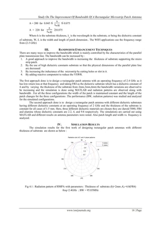
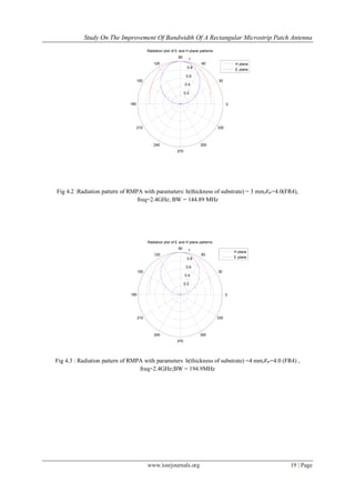
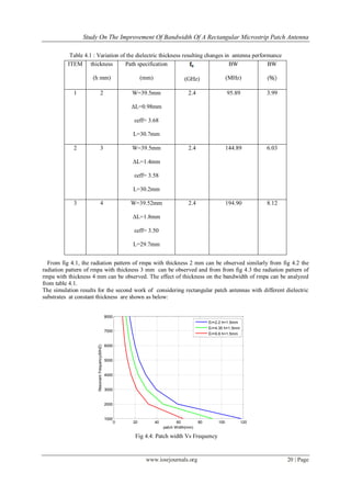
microstrip patch antenna. Firstly by varying the thickness of the substrate (h=2mm, 3mm, 4mm) the bandwidth
percentage is increased from 3.99%, 6.03%, 8.12 %, respectively. Hence, bandwidth enhancement is seen.
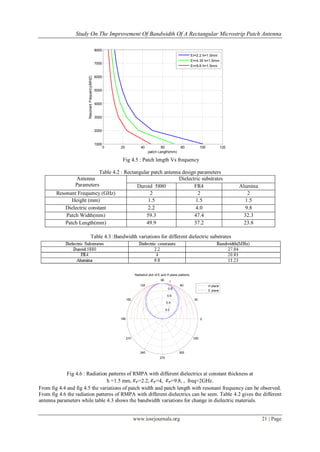
Then a rectangular patch antenna is configured using three different dielectric substrates and bandwidth
variations are analyzed as decreasing the dielectric constant leads to increase in bandwidth Here duroid 5880
having low dielectric constant than FR4 and alumina yields a better bandwidth. Hence, it can be concluded that
for a wide bandwidth the rectangular microstrip patch antenna should be designed with a thicker substrate and
the substrate should be selected with lower dielectric constant.
Acknowledgements
We thank the management of GITAM University for all the support and encouragement rendered in
this project. We also extend our thanks to the Vice Chancellor and Registrar of GITAM University for providing
the required facilities for carrying out this work. Our sincere thanks are also due to the Principal of GITAM
Institute of Technology, Head of the Department of E.C.E and its staff for their kind support.
REFERENCES
[1]. Ramesh garg,Prakash bhartia,Inder bharl,Apisak Ittipiboon.Microstrip antenna design handbook
[2]. A.K Bhattachar jee, S.R Bhadra, D.R. Pooddar and S.K. Chowdhury. 1989. Equivalence of impedance and radiation properties of
square and circular microstrip patch antennas. IEE Proc. 136(Pt, H, 4): 338-342.
[3]. R. G. Voughan. 1988. Two-port higher mode circular microstrip antennas. IEEE, Trans. Antennas Propagat. 36(3): 309-321.
[4]. T Huynh and K.F. Lee. 1995. Single layer single patch wideband microstrip patch antenna. Electronic letters. L (31): 1310-1311.
[5]. Constantine A. Balanis. 2005. ANTENNA THEORY ANALYSIS AND DESIGN. 3
rd
Edition. John Wiley and sons.
[6]. V Zachou. 2004. Transmission line model Design Formula for Microstrip Antenna with Slots. IEEE.
[7]. Prabhakar H.V. 2007. U.K. ELECTRONICS LETTERS. 2
nd
August. 43(16). Jani Ollikainen and Pertti Vainikainen. 1998 Radiation
and Bandwidth Characteristics of Two Planar Multistrip Antennas for Mobile Communication Systems. IEEE Vehicular Technology
Conference. Ottawa, Ontario, Canada. 2: 1186-1190.
[8]. I.J. Bahl and P. Bhartia. 1982. Microstrip Antennas. Artech House Inc. IN.