Downloaded 36 times
![IJRET: International Journal of Research in Engineering and Technology eISSN: 2319-1163 | pISSN: 2321-7308
_______________________________________________________________________________________
Volume: 03 Issue: 08 | Aug-2014, Available @ http://www.ijret.org 200
Dual circular polarization has also been achieved using a singly fed triangular or Pentagonal Microstrip antenna. The radiation efficiency will be 70%. Once the dimensions are obtained the antenna can be simulated on a commercially available IE3D EM simulator. And further optimization and fine tuning of dimensions can be carried out to bring the resonance back at the desired frequency with acceptable return loss. Layout generation can be done in interlaced or AutoCAD software for preparing the mask. Once the mask is pointed on a transparent sheet, the patch can be fabricated using conventional photolithography process. The return loss for the patch antenna can be measured on a network Analyzer. The E-plane and H-plane patterns can be measured in a far-field test set up (preferably in an anechoic chamber) with a standard gain antenna as a transmitting antenna and the Antenna under test as a receiving antenna mounted on a pedestal. 3. CONCLUSIONS Finally 2G spectrums (900MHz-1800MHz) and 3G (1800MHz-2000MHz) spectrums are used by old generation handset antenna but my proposed antenna design is capable of working in both frequencies weather its belongs to 2G or 3G spectrums simultaneously. My multi frequency antenna design is capable of handling two different frequencies simultaneously but in future advancement it’s also possible to design an penta frequency (900MHz/1800MHz/1900MHz/ 2000MHz and 2200MHz) operated antenna also. ACKNOWLEDGEMENTS I am heartily thanks to Technocrats Institute of Technology and Maulana Azad National Institute of Technology, Bhopal for helping me in my research work. REFERENCES [1]. Sheng Tu, Qingsha S. Cheng,Yifan Zhang, John W. Bandler, and Natalia K. Nikolova, “Space Mapping Optimization of Handset Antennas Exploiting Thin-Wire Models”, IEEE Transactions On Antennas And Propagation, Vol. 61, No. 7, July 2013.
[2]. ArpitaSen, Prafulla Chandra Prasad, Neela Chattoraj,“Design and Development of a Single Feed Reconfigurable Dual-Frequency Microstrip Antenna”, IEEE International conference on Communication and Signal Processing, April 3-5, 2013, India [3]. Shaya Karimkashi and Guifu Zhang, “A Dual-Polarized Series-Fed Microstrip Antenna Array With Very High Polarization Purity for Weather Measurements”, IEEE transactions on antennas and propagation, vol. 61, no. 10, October 2013 [4]. Amit A. Deshmukh, AporvaA. Joshi, Ankita R. jain, Tejal A. Tirodkar, and K. P. Ray, “Broadband Proximity fed half U-slot cut Rectangular Microstrip Antennas,“IEEE Third International Conference on Advances in Computing and Communications, June-2013.
[5]. Marija M. Nikolic´, Antonije R. Djordjevic´,and Arye Nehorai, “Microstrip Antennas With Suppressed Radiation in Horizontal Directions and Reduced Coupling”, IEEE transactions on antennas and propagation, vol. 53, no. 11, November 2013. [6]. Ehab K. I. Hamad and Ahmed H. Radwan, “B14. Compact Ultra Wideband Microstrip Fed Printed Monopole Antenna”, 30th NATIONAL RADIO SCIENCE CONFERENCE (NRSC 2013) April 16‐18, 2013, National Telecommunication Institute, Egypt IEEE 2013 [7]. Fang-Yao Kuo, and Ruey-Bing Hwang, “High Isolation X-band Marine Radar Antenna Design”, IEEE 2013-14 [8]. M. Samsuzzaman, M. T. Islam, N .Misran, M.A. Mohd Al, “Dual band X shape Microstrip Patch Antenna for Satellite Applications”, The 4th International Conference on Electrical Engineering and Informatics (ICEEI 2013), November-2013. [9]. Lechen Yang, XueshunShi, KunfengChen, KaiFu, BaoshunZhang, “Analysis of photonic crystal and multi- frequency terahertz microstrip patch antenna”, Elsevier B.V. 31 August 2013 [10]. IEEE Transactions on Antenna and Propagation, vols. AP-17, No. 3, May 1969; AP-22, No. 1, January 1974; and AP-31, No. 6, Part 2, November 1983. [11]. C. A. Balanis, Antenna Theory: Analysis and Design, 2nd ed., Wiley, 1997. [12]. R. Garg, P. Bhartia, I. Bahl and A. Ittipiboon, Microstrip Antenna Design Handbook, Artech House, 2001. [13]. The Integration Of Rectangular SIW Filter and Microstrip Patch Antenna Based On Cascaded Approach by Z.Zakariaa, W.Y.Sama, M.Z.. Abdaziza and M.Muzafar Ismaila in Malaysian Technical Universities Conference on Engineering & Technology 2012, MUCET 2012 published by Elsevier Ltd. BIOGRAPHIES
Mrigendra Pratap Singh received his Bachelor of Engineering in Electronics & Communication Engineering from Rashtrasant Tukadoji Maharaj Nagpur University (Maharashtra) India in 2011 Presently he is doing his Master's degree in Electronics & Communication Engineering from Technocrats Institute of Technology, Bhopal. His area of research is patch antenna and its propagation. He is active member of IEEE Madhya Pradesh Sub Section and IETE.
Prof. Shivraj Singh received his bachelor’s degree in Electronics & Communication engineering from Sagar Institute of Research & Technology, Bhopal in 2007 and Master’s degree in Digital Communication from Technocrats Institute of Technology, Bhopal in 2012. Presently he is working as an Assistant Professor in Technocrats Institute of Technology. His research interest is in the field of antenna and wireless communication. He published several papers in various research journals.](https://image.slidesharecdn.com/designofareconfigurablemulti-frequencycircularlypolarizedmicrostrippatchantenna-140902050111-phpapp01/75/Design-of-a-reconfigurable-multi-frequency-circularly-polarized-microstrip-patch-antenna-4-2048.jpg)

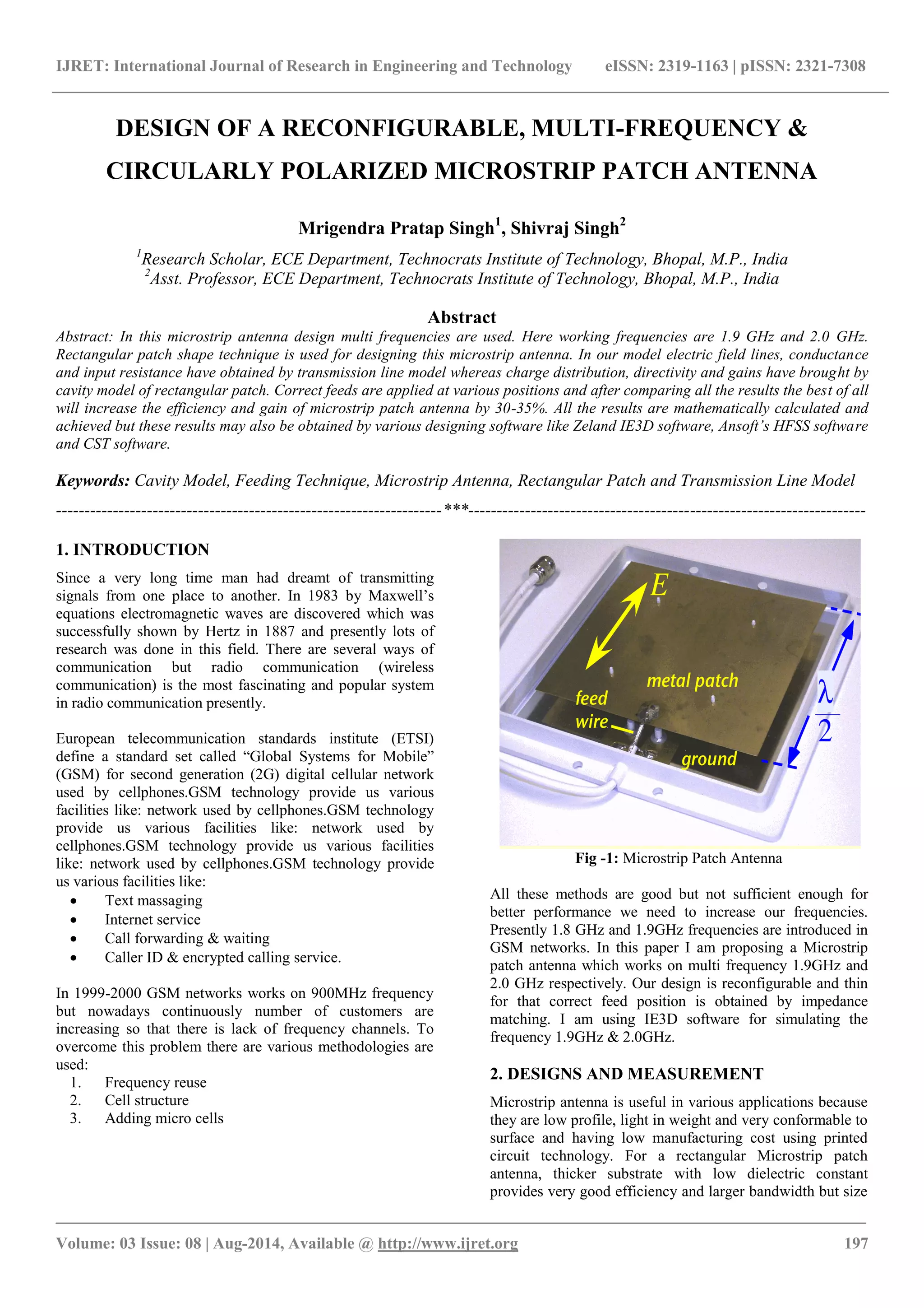
This document describes the design of a reconfigurable, multi-frequency circularly polarized microstrip patch antenna. The antenna is designed to operate at 1.9 GHz and 2.0 GHz. A rectangular patch shape is used with the correct feed position determined through impedance matching. Simulations are performed using IE3D software. The design achieves multi-frequency operation, reconfigurability, and circular polarization with efficiencies estimated to be around 70%.