Downloaded 1,766 times
![References
[1]
G. Kumar and K. P. Ray, Broadband Microstrip Antennas, Artech House,
Norwood, Mass, USA, 2003
[2] C. A. Balanis, Antenna Theory, John Wiley & Sons, Hoboken, NJ, USA,
2nd edition, 2004.
[3]
R. Garg, P. Bhartia, I. Bahl, and A. Ittipiboon,Microstrip Antenna Design
Handbook, Artech House, Norwood, Mass, USA, 2001.
[4]
A Novel Dual Band Circular Microstrip Antenna , International Journal of
Computer Applications.
[5]](https://image.slidesharecdn.com/vishalppt2-131029124122-phpapp02/85/Dual-Band-Microstrip-Antenna-19-320.jpg)

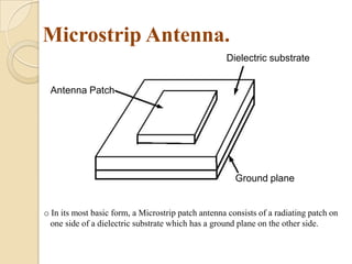
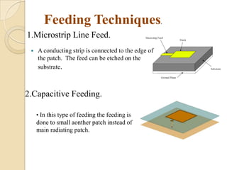
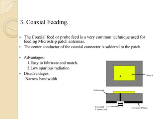
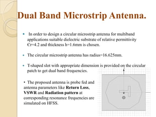
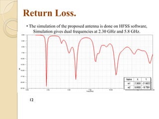
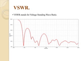
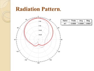
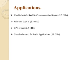
This document summarizes a project on designing a dual band microstrip antenna. It provides an overview of microstrip antennas, including their basic principles and operation, common shapes and feeding techniques. It then describes the design of a circular dual band microstrip antenna with a T-shaped slot to achieve resonance at 2.3 GHz and 5.8 GHz. Simulation results showing return loss, VSWR, and radiation patterns are presented. Potential applications of dual band microstrip antennas in mobile satellite communication systems, wireless LANs, and GPS are also discussed.


![Reflectarray antenna [Antenna]](https://cdn.slidesharecdn.com/ss_thumbnails/antennafinaal-190716164257-thumbnail.jpg?width=640&height=640&fit=bounds)


