Downloaded 124 times
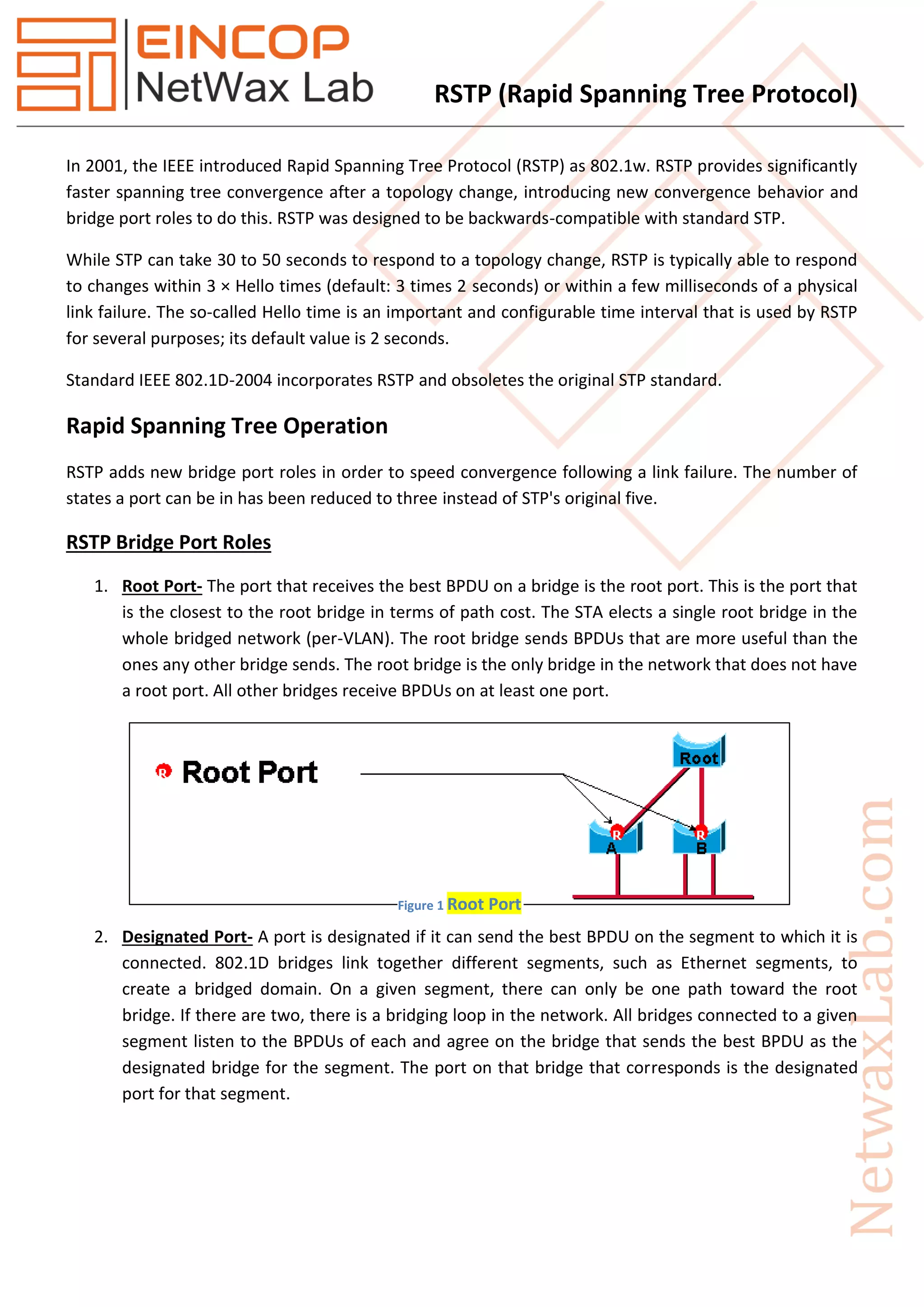
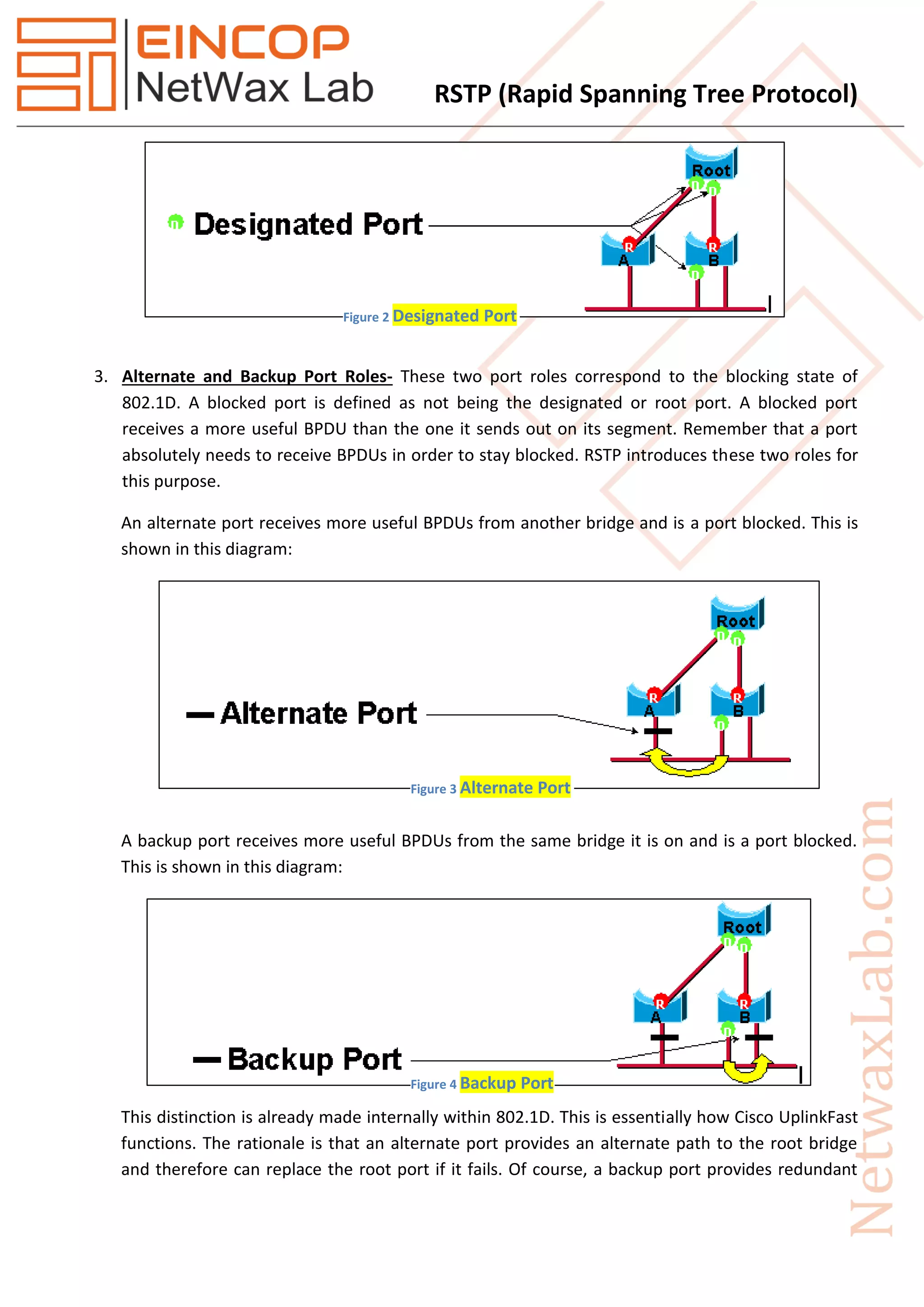
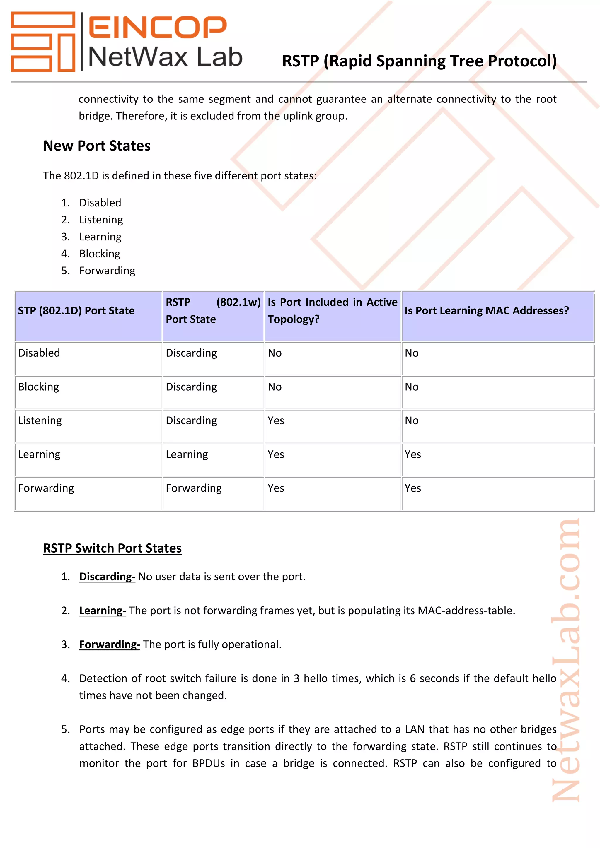
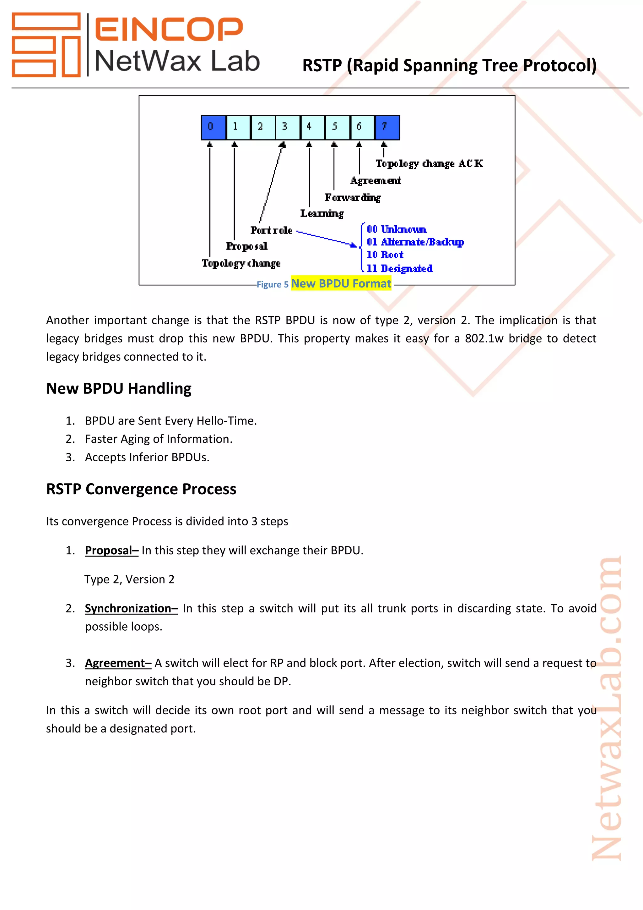
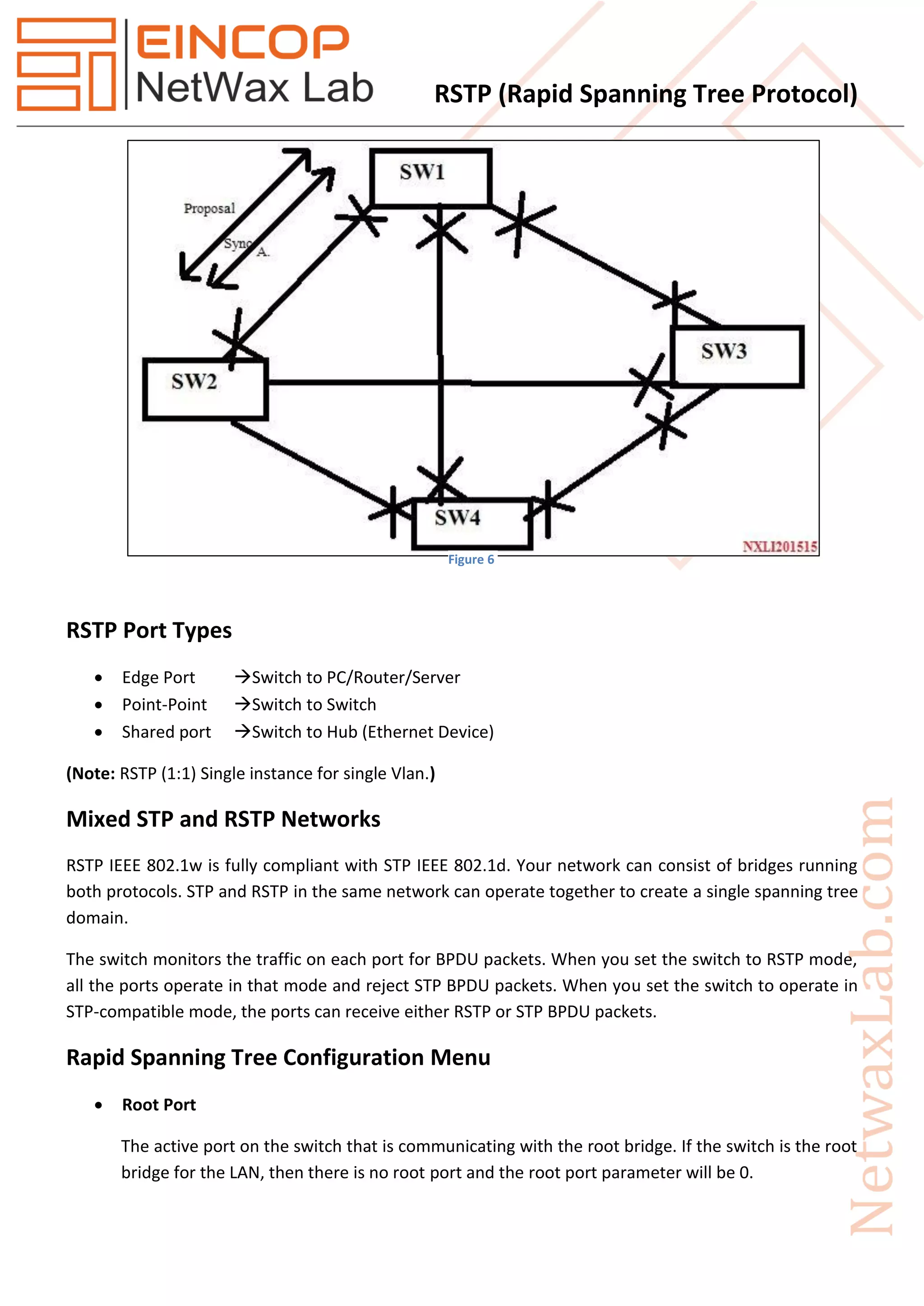

Rapid Spanning Tree Protocol (RSTP), introduced as IEEE 802.1w in 2001, significantly improves the convergence time after topology changes when compared to the original Spanning Tree Protocol (STP), allowing response times within milliseconds. RSTP features three port states (discarding, learning, forwarding) and five port roles (root, designated, alternate, backup, disabled) to enhance efficiency and compatibility with STP. The protocol operates with advanced mechanisms like the proposal/agreement process for rapid transitions and integrates well within networks using both RSTP and STP protocols.


![Coded Agents – with UiPath SDK + LangGraph [Virtual Hands-on Workshop]](https://cdn.slidesharecdn.com/ss_thumbnails/codedagentsdeck-251215155422-5497c599-thumbnail.jpg?width=640&height=640&fit=bounds)


