Download as PDF, PPTX
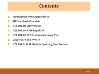
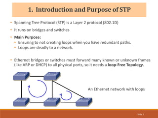
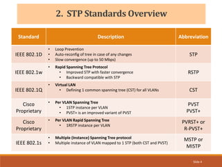

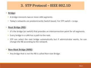
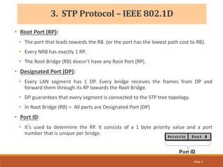
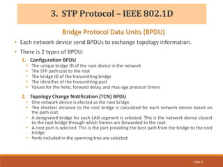
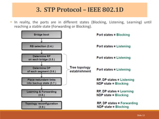
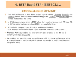
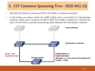
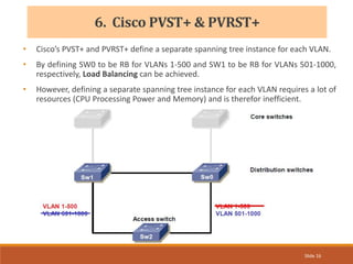
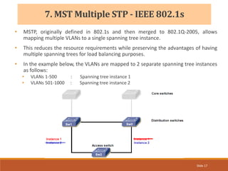


The document provides an overview of the Spanning Tree Protocol (STP), its purpose of preventing network loops in Ethernet networks, and various IEEE standards including STP, Rapid STP (RSTP), and Common Spanning Tree (CST). It discusses the roles of bridges and ports within STP, the election of the root bridge, and the changes introduced in RSTP compared to traditional STP. Additionally, the document touches on Cisco's proprietary protocols and the Multiple Spanning Tree (MST) protocol that maps multiple VLANs to a single STP instance for resource efficiency.