STP is a protocol that prevents bridge loops in Ethernet LANs. There are multiple versions of STP including 802.1D Common STP, 802.1w Rapid STP, and 802.1s Multiple STP. Attacks against STP protocols aim to take over the root bridge role or perform denial of service attacks by flooding bridges with BPDU packets. Countermeasures against these attacks include root guard, BPDU guard, BPDU filtering, and layer 2 PDU rate limiting on switches.
![Attack 2: DoS Using a Flood of
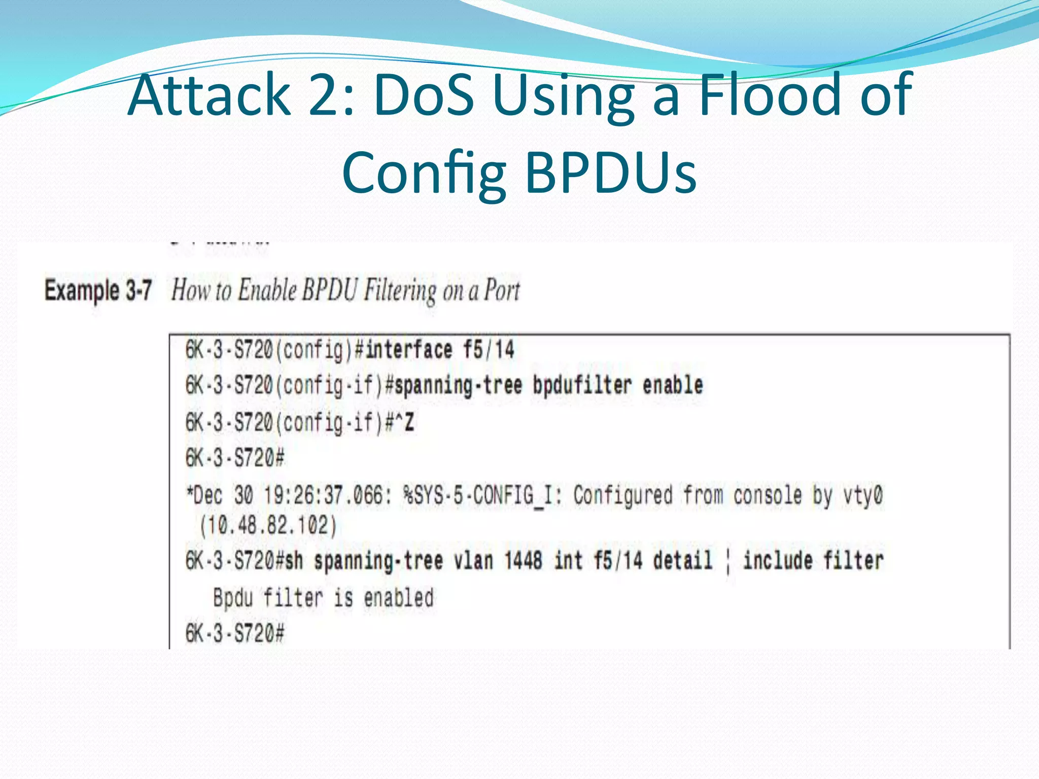
Config BPDUs
Layer 2 PDU Rate Limiter
Available only on certain switches, such as the Supervisor
Engineer 720 for the Catalyst 6500, a third option to stop the
DoS from causing damage exists. It takes the form of a
hardware-based Layer 2 PDU rate limiter. It limits the
number of Layer 2 PDUs (BPDUs, DTP, Port Aggregation
Protocol [PAgP], CDP, VTP frames) destined for the
supervisor engine’s processor. The feature works only on
Catalyst 6500/7600 that are not operating in truncated
mode. The switch uses truncated mode for traffic between
fabric-enabled modules when both fabric-enabled and
nonfabric-enabled modules are installed. In this mode, the
router sends a truncated version of the traffic (the first 64
bytes of the frame) over the switching fabric.](https://image.slidesharecdn.com/attackingthespanningtreeprotocol-130329170910-phpapp02/75/Attacking-the-spanning-tree-protocol-17-2048.jpg)
![Attack 2: DoS Using a Flood of
Config BPDUs
Layer 2 PDU Rate Limiter
(For more information about the various modes of operation of
the Catalyst 6500 switch, see the third entry in the section,
“References.”) The Layer 2 PDU rate limiter is configured as
follows:
Router(config)# mls rate-limit layer2 pdu 200 20 200 L2
PDUs per second, burst of 20 packets
Fine-tuning the rate limiter can be time consuming and error
prone, because it is global to the switch and applicable to
traffic received across all VLANs for various Layer 2 protocols.
However, it can be safely enabled with a fairly high threshold.
As a rough guideline, 2000 PDUs per second is a high
watermark figure for an enterprise class switch. (The rate
limiter prevents only a DoS attack. It does not stop the other
attacks described in this chapter [root hostile takeover, and so
on].)](https://image.slidesharecdn.com/attackingthespanningtreeprotocol-130329170910-phpapp02/75/Attacking-the-spanning-tree-protocol-18-2048.jpg)