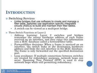
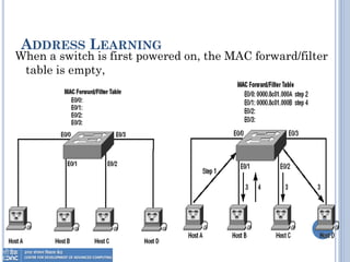
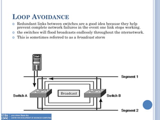
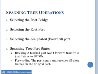
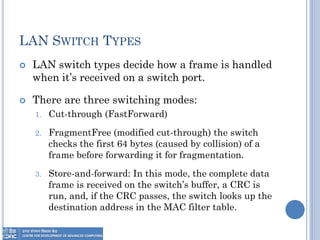
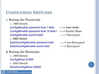
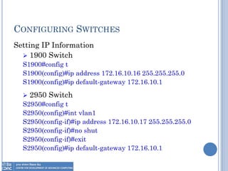
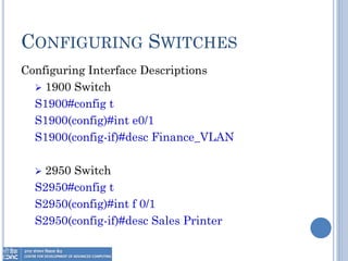
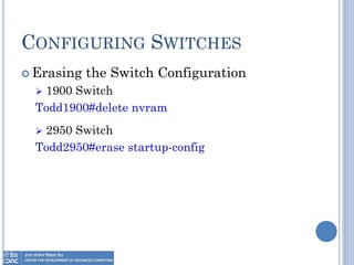
LAYER 2 SWITCHING
By
Anil Kumar Vishwakarma
MCA,MCTS,CCNA
OVERVIEW
 Introduction
 Spanning Tree Protocol
 Spanning Tree Terms
 Spanning Tree Operations
 LAN Switch Types
 Configuring Switches
INTRODUCTION
 Switching Services
 Unlike bridges that use software to create and manage a
filter table, switches use application specific integrated
circuits (ASICs) to build and maintain their filter tables.
 A switch can be viewed as a multiport bridge.
 Three Switch Functions at Layer 2
1. Address learning: Layer 2 switches and bridges
remember the source hardware address of each frame
received on an interface, and they enter this information
into a MAC database called a forward/filter table.
2. Forward/filter decisions: When a frame is received on an
interface, the switch looks at the destination hardware
address and finds the exit interface in the MAC database.
The frame is only forwarded out the specified destination
port.
3. Loop avoidance: If multiple connections between switches
are created for redundancy purposes, network loops can
occur. Spanning Tree Protocol (STP) is used to stop
network loops while still permitting redundancy.
ADDRESS LEARNING
When a switch is first powered on, the MAC forward/filter
table is empty,
FORWARD/FILTER DECISIONS
 When a frame arrives at a switch interface, the
destination hardware address is compared to the
forward/filter MAC database.
 If the destination hardware address is known
and listed in the database, the frame is sent out
only the correct exit interface.
 The switch doesn’t transmit the frame out any
interface except for the destination interface.
 This preserves bandwidth on the other network
segments and is called frame filtering.
LOOP AVOIDANCE
 Redundant links between switches are a good idea because they help
prevent complete network failures in the event one link stops working.
 the switches will flood broadcasts endlessly throughout the nternetwork.
 This is sometimes referred to as a broadcast storm
SPANNING TREE PROTOCOL
 STP’s main task is to stop network loops from
occurring on your layer 2 network switches.
 It monitors the network to find all links, making
sure that no loops occur by shutting down any
redundant links.
 STP uses the spanning-tree algorithm (STA) to
first create a topology database, then search out
and destroy redundant links.
 With STP running, frames will be forwarded only
on the premium, STP-picked links.
SPANNING TREE TERMS
 Bridge ID: It is determined by a combination of the bridge
priority (32,768 by default on all Cisco switches) and the base
MAC address. The bridge with the lowest bridge ID becomes the
root bridge in the network.
 Root bridge: is the bridge with the best bridge ID (the lowest
bridge ID).
 Nonroot bridge: These are all bridges that are not the root
bridge. Nonroot bridges exchange BPDUs with all bridges and
update the STP topology database on all switches.
 BPDU: Bridge Protocol Data Unit (BPDU) the name of packet
that they send to one neighbor with the one that they receive
from another neighbor.
 Root port: The root port is always the link directly connected to
the root bridge, or the shortest path to the root bridge.
SPANNING TREE TERMS
 Designated port A designated port is one that has been
determined as having the best (lowest) cost. A designated
port will be marked as a forwarding port.
 Port cost Port cost determines when multiple links are
used between two switches and none are root ports. The
cost of a link is determined by the bandwidth of a link.
 Nondesignated port is one with a higher cost than the
designated port. Nondesignated ports are put in blocking
mode—they are not forwarding ports.
 Blocked port A blocked port is the port that will not
forward frames, in order to prevent loops. However, a
blocked port will always listen to frames.
SPANNING TREE OPERATIONS
1. Selecting the Root Bridge
2. Selecting the Root Port
3. Selecting the designated (Forward) port.
4. Spanning-Tree Port States
 Blocking A blocked port won’t forward frames; it
just listens to BPDUs.
 Forwarding The port sends and receives all data
frames on the bridged port.
LAN SWITCH TYPES
 LAN switch types decide how a frame is handled
when it’s received on a switch port.
 There are three switching modes:
1. Cut-through (FastForward)
2. FragmentFree (modified cut-through) the switch
checks the first 64 bytes (caused by collision) of a
frame before forwarding it for fragmentation.
3. Store-and-forward: In this mode, the complete data
frame is received on the switch’s buffer, a CRC is
run, and, if the CRC passes, the switch looks up the
destination address in the MAC filter table.
CONFIGURING SWITCHES
 Setting the Passwords
 1900 Switch
(config)#enable password level 1 kkkk -----> User mode
(config)#enable password level 15 kkkk1 -----> Enable Mode
(config)#enable secret todd2 -----> Encrypted
 2950 Switch
Switch(config)#enable password todd -----> non Encrypted
Switch(config)#enable secret todd -----> Encrypted
 Setting the Hostname
 1900 Switch
(config)#host S1900
 2950 Switch
Switch(config)#host S2950
CONFIGURING SWITCHES
Setting IP Information
 1900 Switch
S1900#config t
S1900(config)#ip address 172.16.10.16 255.255.255.0
S1900(config)#ip default-gateway 172.16.10.1
 2950 Switch
S2950#config t
S2950(config)#int vlan1
S2950(config-if)#ip address 172.16.10.17 255.255.255.0
S2950(config-if)#no shut
S2950(config-if)#exit
S2950(config)#ip default-gateway 172.16.10.1
CONFIGURING SWITCHES
Configuring Interface Descriptions
 1900 Switch
S1900#config t
S1900(config)#int e0/1
S1900(config-if)#desc Finance_VLAN
 2950 Switch
S2950#config t
S2950(config)#int f 0/1
S2950(config-if)#desc Sales Printer
CONFIGURING SWITCHES
 Erasing the Switch Configuration
 1900 Switch
Todd1900#delete nvram
 2950 Switch
Todd2950#erase startup-config
Thank You

Day 4 LAYER 2 SWITCHING

  • 1.
    LAYER 2 SWITCHING By AnilKumar Vishwakarma MCA,MCTS,CCNA
  • 3.
    OVERVIEW  Introduction  SpanningTree Protocol  Spanning Tree Terms  Spanning Tree Operations  LAN Switch Types  Configuring Switches
  • 4.
    INTRODUCTION  Switching Services Unlike bridges that use software to create and manage a filter table, switches use application specific integrated circuits (ASICs) to build and maintain their filter tables.  A switch can be viewed as a multiport bridge.  Three Switch Functions at Layer 2 1. Address learning: Layer 2 switches and bridges remember the source hardware address of each frame received on an interface, and they enter this information into a MAC database called a forward/filter table. 2. Forward/filter decisions: When a frame is received on an interface, the switch looks at the destination hardware address and finds the exit interface in the MAC database. The frame is only forwarded out the specified destination port. 3. Loop avoidance: If multiple connections between switches are created for redundancy purposes, network loops can occur. Spanning Tree Protocol (STP) is used to stop network loops while still permitting redundancy.
  • 5.
    ADDRESS LEARNING When aswitch is first powered on, the MAC forward/filter table is empty,
  • 6.
    FORWARD/FILTER DECISIONS  Whena frame arrives at a switch interface, the destination hardware address is compared to the forward/filter MAC database.  If the destination hardware address is known and listed in the database, the frame is sent out only the correct exit interface.  The switch doesn’t transmit the frame out any interface except for the destination interface.  This preserves bandwidth on the other network segments and is called frame filtering.
  • 7.
    LOOP AVOIDANCE  Redundantlinks between switches are a good idea because they help prevent complete network failures in the event one link stops working.  the switches will flood broadcasts endlessly throughout the nternetwork.  This is sometimes referred to as a broadcast storm
  • 8.
    SPANNING TREE PROTOCOL STP’s main task is to stop network loops from occurring on your layer 2 network switches.  It monitors the network to find all links, making sure that no loops occur by shutting down any redundant links.  STP uses the spanning-tree algorithm (STA) to first create a topology database, then search out and destroy redundant links.  With STP running, frames will be forwarded only on the premium, STP-picked links.
  • 9.
    SPANNING TREE TERMS Bridge ID: It is determined by a combination of the bridge priority (32,768 by default on all Cisco switches) and the base MAC address. The bridge with the lowest bridge ID becomes the root bridge in the network.  Root bridge: is the bridge with the best bridge ID (the lowest bridge ID).  Nonroot bridge: These are all bridges that are not the root bridge. Nonroot bridges exchange BPDUs with all bridges and update the STP topology database on all switches.  BPDU: Bridge Protocol Data Unit (BPDU) the name of packet that they send to one neighbor with the one that they receive from another neighbor.  Root port: The root port is always the link directly connected to the root bridge, or the shortest path to the root bridge.
  • 10.
    SPANNING TREE TERMS Designated port A designated port is one that has been determined as having the best (lowest) cost. A designated port will be marked as a forwarding port.  Port cost Port cost determines when multiple links are used between two switches and none are root ports. The cost of a link is determined by the bandwidth of a link.  Nondesignated port is one with a higher cost than the designated port. Nondesignated ports are put in blocking mode—they are not forwarding ports.  Blocked port A blocked port is the port that will not forward frames, in order to prevent loops. However, a blocked port will always listen to frames.
  • 11.
    SPANNING TREE OPERATIONS 1.Selecting the Root Bridge 2. Selecting the Root Port 3. Selecting the designated (Forward) port. 4. Spanning-Tree Port States  Blocking A blocked port won’t forward frames; it just listens to BPDUs.  Forwarding The port sends and receives all data frames on the bridged port.
  • 12.
    LAN SWITCH TYPES LAN switch types decide how a frame is handled when it’s received on a switch port.  There are three switching modes: 1. Cut-through (FastForward) 2. FragmentFree (modified cut-through) the switch checks the first 64 bytes (caused by collision) of a frame before forwarding it for fragmentation. 3. Store-and-forward: In this mode, the complete data frame is received on the switch’s buffer, a CRC is run, and, if the CRC passes, the switch looks up the destination address in the MAC filter table.
  • 13.
    CONFIGURING SWITCHES  Settingthe Passwords  1900 Switch (config)#enable password level 1 kkkk -----> User mode (config)#enable password level 15 kkkk1 -----> Enable Mode (config)#enable secret todd2 -----> Encrypted  2950 Switch Switch(config)#enable password todd -----> non Encrypted Switch(config)#enable secret todd -----> Encrypted  Setting the Hostname  1900 Switch (config)#host S1900  2950 Switch Switch(config)#host S2950
  • 14.
    CONFIGURING SWITCHES Setting IPInformation  1900 Switch S1900#config t S1900(config)#ip address 172.16.10.16 255.255.255.0 S1900(config)#ip default-gateway 172.16.10.1  2950 Switch S2950#config t S2950(config)#int vlan1 S2950(config-if)#ip address 172.16.10.17 255.255.255.0 S2950(config-if)#no shut S2950(config-if)#exit S2950(config)#ip default-gateway 172.16.10.1
  • 15.
    CONFIGURING SWITCHES Configuring InterfaceDescriptions  1900 Switch S1900#config t S1900(config)#int e0/1 S1900(config-if)#desc Finance_VLAN  2950 Switch S2950#config t S2950(config)#int f 0/1 S2950(config-if)#desc Sales Printer
  • 16.
    CONFIGURING SWITCHES  Erasingthe Switch Configuration  1900 Switch Todd1900#delete nvram  2950 Switch Todd2950#erase startup-config
  • 17.