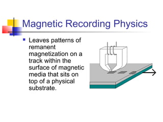
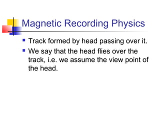
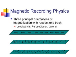
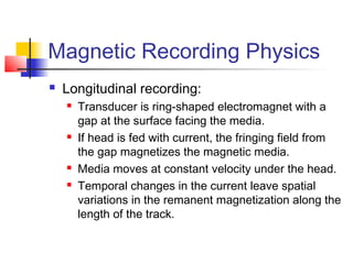
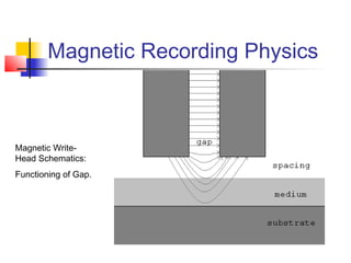
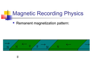
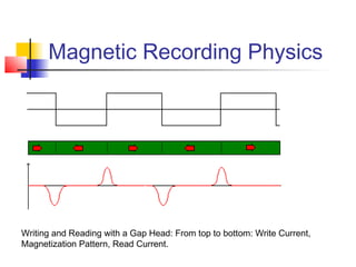
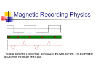
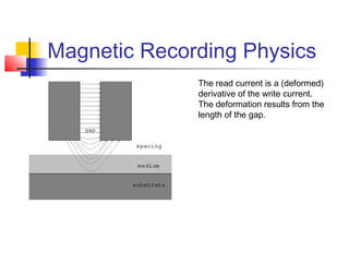
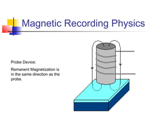
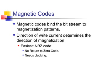
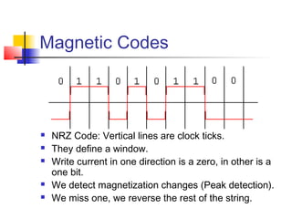
COEN 180
Magnetic Recording
Magnetic Recording Physics
 Leaves patterns of
remanent
magnetization on a
track within the
surface of magnetic
media that sits on
top of a physical
substrate.
Magnetic Recording Physics
 Track formed by head passing over it.
 We say that the head flies over the
track, i.e. we assume the view point of
the head.
Magnetic Recording Physics
 Three principal orientations of
magnetization with respect to a track:
 Longitudinal, Perpendicular, Lateral.
Magnetic Recording Physics
 Longitudinal recording:
 Transducer is ring-shaped electromagnet with a
gap at the surface facing the media.
 If head is fed with current, the fringing field from
the gap magnetizes the magnetic media.
 Media moves at constant velocity under the head.
 Temporal changes in the current leave spatial
variations in the remanent magnetization along the
length of the track.
Magnetic Recording Physics
Magnetic Write-
Head Schematics:
Functioning of Gap.
Magnetic Recording Physics
 Remanent magnetization pattern:
Magnetic Recording Physics
 Read head used to be the same as
write head.
 Passing the gap head over the track
would let the magnetization pattern
cause an induced read current.
Magnetic Recording Physics
Writing and Reading with a Gap Head: From top to bottom: Write Current,
Magnetization Pattern, Read Current.
Magnetic Recording Physics
The read current is a (deformed) derivative of the write current. The deformation
results from the length of the gap.
Magnetic Recording Physics
The read current is a (deformed)
derivative of the write current.
The deformation results from the
length of the gap.
Magnetic Recording Physics
 Perpendicular Recording
 Uses a Probe Head.
 Has the potential for better magnetization
retention.
 MEMS
Magnetic Recording Physics
Probe Device:
Remanent Magnetization is
in the same direction as the
probe.
Magnetic Recording Physics
 Hard drives currently use exclusively
longitudinal magnetization.
 Switch to perpendicular is expected in
the near future.
 Better retention  Higher Areal Densities.
 Lateral never used.
Magnetic Recording Physics
 Magneto-Resistive Effect (MR)
 GMR
 Standard read head.
Magnetic Recording Physics
MR-Effect: Magnetic field (red) moves electron flow in the
sense current (yellow) up by an angle of θ. The magneto-
resistive material (blue) has different resistance based on
the angle θ.
Magnetic Recording Physics
 MR head directly reads the magnetic
flux.
 Gap head reads the changes in
magnetic flux.
 MR head can adjust the sense current.
 Better sensitivity.
Data Storage on Rigid Disks
 Single platter or stack of platters
 Thin magnetic coating
 Rotate at high speeds.
 Magnetic recording heads mounted on arms record
data on all surfaces.
 Heads moved across the disk surface by a high speed
actuator.
 Circular tracks.
 Cylinder
 Formed by the tracks on all surfaces by same actuator
position.
 The tracks are broken up into sectors (or disk blocks).
 The old format of 512B per block still remains in effect.
Data Storage on Rigid Disks
 Hard drives rotate at constant angular
speed.
 Constant linear velocity impractical.
 Heads see more track in the outer layers.
 Nr. of sectors per track varies.
 Remains constant in a “band”.
 Data density increases in a band as we
move to the inside.
Data Storage on Rigid Disks
 The platter consists of a rigid aluminium
or glass platter, coated with various
coats.
 Rigid platter
 Magnetizable thin film that actually stores the
data.
 Overcoat
 Lubricant

Protects (somewhat) against head crashes
Data Storage on Rigid Disks
 Use surrounding air pressure to maintain the
proper distance between head and the surface
 The spacing controls the focus of the head; if the
head is further away from the surface, then it will read
from and write to a wider area.
 To increase data densities, the head - surface spacing
has decreased dramatically.
 The head can no longer be parked on the surface
during power down (when the rotation ceases, the
head will actually land).
 Special landing area.

Surface is treated to allow air to get between the head
and the surface.

When head flies again, move over the data tracks.
Data Storage on Rigid Disks
 Data Access:
 Seek

Place head over right track.

Servo: Find the right track.
 Used to be done with a special servo-surface on
one of the platters.
 No servo data is embedded in the sector gaps.
 Rotational Delay

On average half the time of a disk revolution.

AKA latency.
 Transfer Time
Data Storage on Rigid Disks
 Performance Parameters:
 Capacity / Data Density

Disks with smaller form factors have become
popular in niche applications.

Trend towards smaller disk, that can rotate faster.
 Data density is a two-dimensional value:

tpi: Tracks per inch: How far do tracks have to be
separated.

bpi: bits per inch: How many sectors on a single
track.
Data Storage on Rigid Disks
 Operations on adjacent
tracks can interfere with
each other:
 Track misregistration.
 During read

Too much noise.
 During write

Data written can be
unreadable.

Data on next track can
become unreadable.
Data Storage on Rigid Disks
 Data Density:
 Limited by the ability to distinguish distinct
magnetization patterns.
 Pulse superimposition theory:

Flux from nearby magnetization patterns
influences reads.
Data Storage on Rigid Disks
Read current picked up by a
magnetic gap head.
Red line: Read current in absence of the
other change.
Green line: Resulting read current.
Top: No interference.
Middle: Peak shifts to the outside.
Bottom: Peak shift much more
pronounced.
Data Storage on Rigid Disks
 Seek time:
 Determined by the speed of the actuator.
 Determined by the capacity of the servo
mechanism.
 If the actuator moves very fast, then there is more
of a settling time.
Data Storage on Rigid Disks
 Latency:
 Solely determined by rotational speed.
 Rotational speed limited by the
aerodynamics of the platter.
 Larger platters cannot be rotated as fast as
smaller ones.
Data Storage on Rigid Disks
 Access Time:
 Random Access

Seek

Latency

Transfer
 Stream (block after block)

Only first seek, only first latency.

Zero Latency Disk
 Starts reading whenever data needed appears under the
head.
 Others wait for the first block of the stream.

Occasional track to neighboring track seeks.
Data Storage on Rigid Disks
 Errors
 Disks are not intended for error-free
operations.
 Soft error

Error cannot be repeated.
 Hard error

Cannot do the operation.
Data Storage on Rigid Disks
 Interference
 Cross-talk between different channels or
through feedthrough.
 Track Misregistration.
 Imperfect Overwrites / Incomplete Erasures.
 Side fringing

when the head picks up flux changes from an
adjacent track.
 Bit loss due to Intersymbol Interference.
Data Storage on Rigid Disks
 Noise
 Media noise

Defects or random media properties
 Spot on the surface does not retain magnetization because of a
manufacturing problem or because of a previous head crash.
 A modern disk drive has spare sectors on each track and
complete spare tracks to substitute for sectors that have these
defects.
 Even without an outright defect, the magnetic properties of the
medium vary.
 Electronic Noise

caused by random fluctuations typically in the first stage
amplifier in the reproducing circuit.
 Head Noise:

The magnetic flux in both write and read heads is subject to
thermally induced fluctuations in time.
Data Storage on Rigid Disks
 Error rate is controlled through the use of
Error Control Codes.
 In addition, each sector has a checksum
to prevent false data from being read.
Data Storage on Rigid Disks
 Reliability
 Device failure

SMART (UCSD MRC) can predict 50% failures
based on higher rate of soft errors.
 Block failure: bit rot
 Data corruption: bit rot that is undetected.
Data Storage on Rigid Disks
 Power Use
 Major problems for laptops.
 Major problems for very large disk-based
storage centers.
 Various proposals of spinning up / down
strategies:

MAID: Massive Arrays of Idle Disks.
 System Interface:
 SCSI vs. IDE.
Magnetic Codes
 Magnetic codes bind the bit stream to
magnetization patterns.
 Direction of write current determines the
direction of magnetization
 Easiest: NRZ code

No Return to Zero Code.

Needs clocking.
Magnetic Codes
 NRZ Code: Vertical lines are clock ticks.
 They define a window.
 Write current in one direction is a zero, in other is a
one bit.
 We detect magnetization changes (Peak detection).
 We miss one, we reverse the rest of the string.
Magnetic Codes
 NRZI
 No Return on Zero Inverted
 Switch magnetization pattern = 1
 No switch during window = 0.
 Has difficulties of counting with long strings
of zeroes.
Magnetic Codes
NRZ (top) and NRZI (below)
Magnetic Codes
 Phase encoding:
 Transition up for a one in window
 Transition down for a zero in window
 Two or more zeroes / ones in a row:

Additional transition in the middle.
 Self-clocking
Magnetic Codes
Top to bottom:
PE
FM
MFM
Magnetic Code
 Self-clocking:
 Transitions are never spaced out.
 Easy to synchronize clock to transitions.
Magnetic Codes
 Problem with PM:
 Up to twice as many flux changes than
transitions.
 Limits bit density because flux changes too
close together leads to noisy signal.
Magnetic Codes
 FM
 Frequency Modulation
 Transition in the middle of the cell defines
a one bit
 Absence means a zero bit.
Magnetic Codes
Top to bottom:
PE
FM
MFM
Magnetic Codes
 FM still has potentially up to twice as
many flux changes than bits.
 Self clocking.
Magnetic Codes
 MFM
 Delay Modulation / Miller Code
 Transition in the middle of the cell for a one.
 No transition in the middle of the cell for a zero bit.
 Additional transition on the window boundary
between two zeroes.
 Number of flux changes equals the number of bits.
Magnetic Codes
Top to bottom:
PE
FM
MFM
Magnetic Codes
 Generate MFM by a state
diagram.
 Data bits determine transition.
 Bits in state our output when
state is reached.

First bit for the clock window.

Second bit for the transition /
lack of transition within the
window.
Magnetic Codes
Top to bottom:
PE
FM
MFM
Magnetic Codes
 Modulation Codes
 Transform data bit string into a magnetic code.
 Written on magnetic medium as an NRZI waveform.
 3 Parameters:

d = minimum of zeroes between consecutive ones.

k = maximum of zeroes between consecutive ones.

Data density: ratio of x data bits over y magnetic code bits.
 Important for capacity:

Large values of d are important for data density:
 Flux transitions are spaced out.

Lower values of k indicate ease of synchronizing clocks.
Magnetic Codes
 ½(2,7) code
Data Code Word
10 0100
11 1000
000 000100
010 100100
011 001000
0010 00100100
0011 00001000
Magnetic Codes
 PRML channel
 Uses maximum likelihood decoding (ML)
 Partial response:

Readback pulses from adjacent transitions are allowed
to interfere with each other.

ML decoding unravels the results of interference.
 Write Precompensation
 Predistorting the write data before they are sent to
write driver

transitions are correctly placed when read.
Disk Defects
 Channel impairments
 Intersymbol interference
 Off-track interference
 Amplifier noise
 Disk defects

Random noise associated with the random
nature of the disk surface without defects.

Media defect.
Error Correcting Code
 Disks use error detection and error
correction
 Reed Solomon code example:

38 bytes added to 512 data field

Probability of uncorrectable error moves from
10-7
per bit to 8.8*10-16
.
Hard Drive Reliability
 Measured in Mean Time Between
Failure
 Typically quoted at > 106
hours
 Gives the probability of failure during the
economic lifespan of disk, not expected
life span.

Note: Data is expected to survive centuries
Hard Drive Reliability
 Disk Infant Mortality
 Disk drives fail at significantly higher rates during the first
year.
 Typical failure rate curve:
Hard Drive Reliability
 IDEMA proposal:
 Split MTBF rates in four different rates

0 months - 3 months

4 months – 6 months

7 months – 12 months

13 months - EODL
Hard Drive Reliability
 Disk Infant Mortality becomes
noticeable for management when
setting up redundancy strategies for
very large arrays of drives.
 Either:
 Increase redundancy of data stored
partially on young drives.
 Use additional burn-in times
Hard Drive Reliability
 Stated Service Life
 Expected service time of drive, usually rather
short. (~ 3 years)
 Design life
 Time span that a disk drive should be functioning
reliably.
 Because of technical obsolescence (performance,
capacity) < 7 years.
 Warranty Length
Hard Drive Reliability
 Reliability Factors
 Start / Stop Rates

Spinning down disk creates reliability problems.
 Counter measures:

Special “Landing zones” (Desktop)

Ramping (Laptop)
 Power On / Off cycles
 Air pressure

Air cushion is needed to place head at correct
distance
Hard Drive Reliability
 Reliability Factors
 Temperature (Cooling)
 Vibrations

Relevant if disks are put together in a rack.
Hard Drive Reliability
 Bad Batch Problem
 Anecdotes of “bad batches”
 Tend to show up in the first year
 But not fast enough to be caught by
quality.
 Usually dealt with silently through the
warranty process
Hard Drive Reliability
 Hard Failure Modes
 Mechanical Failures

stuck bearings, actuator problems, …
 Head and Head Assembly Failures

head crash, bad wiring, …
 Media Failures
 Logic Board / Firmware Failures
Hard Drive Reliability
 Shock Resistance
Quantum Corporation,
http://www.storagereview.com/guide2000/ref/hdd/perf/qual/features.html
Hard Drive Reliability
 SMART
 (Self-Monitoring Analysis and Reporting
Technology )
 Many hard errors are predictable

30% current implementations

40% - 60% with advanced decision making
Get smartctl for linux at smartmontools.sourceforge.net
Hard Drive Reliability
 SMART
 SMART spec (SFF-8035i) 1996

Lists of 30 attributes
 read error rates
 seek error rates

Attribute exceeding a threshold:
 Disk is expected to die within 24 hours
 Disk is beyond design / usage lifetime
 ATA-4

Internal attribute table is dropped

Disk return OK or Not-OK
 ATA-5

Adds ATA error logs and commands to run self-tests

Magnetic recording By Diks

  • 1.
  • 2.
    Magnetic Recording Physics Leaves patterns of remanent magnetization on a track within the surface of magnetic media that sits on top of a physical substrate.
  • 3.
    Magnetic Recording Physics Track formed by head passing over it.  We say that the head flies over the track, i.e. we assume the view point of the head.
  • 4.
    Magnetic Recording Physics Three principal orientations of magnetization with respect to a track:  Longitudinal, Perpendicular, Lateral.
  • 5.
    Magnetic Recording Physics Longitudinal recording:  Transducer is ring-shaped electromagnet with a gap at the surface facing the media.  If head is fed with current, the fringing field from the gap magnetizes the magnetic media.  Media moves at constant velocity under the head.  Temporal changes in the current leave spatial variations in the remanent magnetization along the length of the track.
  • 6.
    Magnetic Recording Physics MagneticWrite- Head Schematics: Functioning of Gap.
  • 7.
    Magnetic Recording Physics Remanent magnetization pattern:
  • 8.
    Magnetic Recording Physics Read head used to be the same as write head.  Passing the gap head over the track would let the magnetization pattern cause an induced read current.
  • 9.
    Magnetic Recording Physics Writingand Reading with a Gap Head: From top to bottom: Write Current, Magnetization Pattern, Read Current.
  • 10.
    Magnetic Recording Physics Theread current is a (deformed) derivative of the write current. The deformation results from the length of the gap.
  • 11.
    Magnetic Recording Physics Theread current is a (deformed) derivative of the write current. The deformation results from the length of the gap.
  • 12.
    Magnetic Recording Physics Perpendicular Recording  Uses a Probe Head.  Has the potential for better magnetization retention.  MEMS
  • 13.
    Magnetic Recording Physics ProbeDevice: Remanent Magnetization is in the same direction as the probe.
  • 14.
    Magnetic Recording Physics Hard drives currently use exclusively longitudinal magnetization.  Switch to perpendicular is expected in the near future.  Better retention  Higher Areal Densities.  Lateral never used.
  • 15.
    Magnetic Recording Physics Magneto-Resistive Effect (MR)  GMR  Standard read head.
  • 16.
    Magnetic Recording Physics MR-Effect:Magnetic field (red) moves electron flow in the sense current (yellow) up by an angle of θ. The magneto- resistive material (blue) has different resistance based on the angle θ.
  • 17.
    Magnetic Recording Physics MR head directly reads the magnetic flux.  Gap head reads the changes in magnetic flux.  MR head can adjust the sense current.  Better sensitivity.
  • 18.
    Data Storage onRigid Disks
  • 19.
    Data Storage onRigid Disks  Single platter or stack of platters  Thin magnetic coating  Rotate at high speeds.  Magnetic recording heads mounted on arms record data on all surfaces.  Heads moved across the disk surface by a high speed actuator.  Circular tracks.  Cylinder  Formed by the tracks on all surfaces by same actuator position.  The tracks are broken up into sectors (or disk blocks).  The old format of 512B per block still remains in effect.
  • 20.
    Data Storage onRigid Disks
  • 21.
    Data Storage onRigid Disks
  • 22.
    Data Storage onRigid Disks  Hard drives rotate at constant angular speed.  Constant linear velocity impractical.  Heads see more track in the outer layers.  Nr. of sectors per track varies.  Remains constant in a “band”.  Data density increases in a band as we move to the inside.
  • 23.
    Data Storage onRigid Disks  The platter consists of a rigid aluminium or glass platter, coated with various coats.  Rigid platter  Magnetizable thin film that actually stores the data.  Overcoat  Lubricant  Protects (somewhat) against head crashes
  • 24.
    Data Storage onRigid Disks  Use surrounding air pressure to maintain the proper distance between head and the surface  The spacing controls the focus of the head; if the head is further away from the surface, then it will read from and write to a wider area.  To increase data densities, the head - surface spacing has decreased dramatically.  The head can no longer be parked on the surface during power down (when the rotation ceases, the head will actually land).  Special landing area.  Surface is treated to allow air to get between the head and the surface.  When head flies again, move over the data tracks.
  • 25.
    Data Storage onRigid Disks
  • 26.
    Data Storage onRigid Disks  Data Access:  Seek  Place head over right track.  Servo: Find the right track.  Used to be done with a special servo-surface on one of the platters.  No servo data is embedded in the sector gaps.  Rotational Delay  On average half the time of a disk revolution.  AKA latency.  Transfer Time
  • 27.
    Data Storage onRigid Disks  Performance Parameters:  Capacity / Data Density  Disks with smaller form factors have become popular in niche applications.  Trend towards smaller disk, that can rotate faster.  Data density is a two-dimensional value:  tpi: Tracks per inch: How far do tracks have to be separated.  bpi: bits per inch: How many sectors on a single track.
  • 28.
    Data Storage onRigid Disks  Operations on adjacent tracks can interfere with each other:  Track misregistration.  During read  Too much noise.  During write  Data written can be unreadable.  Data on next track can become unreadable.
  • 29.
    Data Storage onRigid Disks  Data Density:  Limited by the ability to distinguish distinct magnetization patterns.  Pulse superimposition theory:  Flux from nearby magnetization patterns influences reads.
  • 30.
    Data Storage onRigid Disks Read current picked up by a magnetic gap head. Red line: Read current in absence of the other change. Green line: Resulting read current. Top: No interference. Middle: Peak shifts to the outside. Bottom: Peak shift much more pronounced.
  • 31.
    Data Storage onRigid Disks  Seek time:  Determined by the speed of the actuator.  Determined by the capacity of the servo mechanism.  If the actuator moves very fast, then there is more of a settling time.
  • 32.
    Data Storage onRigid Disks  Latency:  Solely determined by rotational speed.  Rotational speed limited by the aerodynamics of the platter.  Larger platters cannot be rotated as fast as smaller ones.
  • 33.
    Data Storage onRigid Disks  Access Time:  Random Access  Seek  Latency  Transfer  Stream (block after block)  Only first seek, only first latency.  Zero Latency Disk  Starts reading whenever data needed appears under the head.  Others wait for the first block of the stream.  Occasional track to neighboring track seeks.
  • 34.
    Data Storage onRigid Disks  Errors  Disks are not intended for error-free operations.  Soft error  Error cannot be repeated.  Hard error  Cannot do the operation.
  • 35.
    Data Storage onRigid Disks  Interference  Cross-talk between different channels or through feedthrough.  Track Misregistration.  Imperfect Overwrites / Incomplete Erasures.  Side fringing  when the head picks up flux changes from an adjacent track.  Bit loss due to Intersymbol Interference.
  • 36.
    Data Storage onRigid Disks  Noise  Media noise  Defects or random media properties  Spot on the surface does not retain magnetization because of a manufacturing problem or because of a previous head crash.  A modern disk drive has spare sectors on each track and complete spare tracks to substitute for sectors that have these defects.  Even without an outright defect, the magnetic properties of the medium vary.  Electronic Noise  caused by random fluctuations typically in the first stage amplifier in the reproducing circuit.  Head Noise:  The magnetic flux in both write and read heads is subject to thermally induced fluctuations in time.
  • 37.
    Data Storage onRigid Disks  Error rate is controlled through the use of Error Control Codes.  In addition, each sector has a checksum to prevent false data from being read.
  • 38.
    Data Storage onRigid Disks  Reliability  Device failure  SMART (UCSD MRC) can predict 50% failures based on higher rate of soft errors.  Block failure: bit rot  Data corruption: bit rot that is undetected.
  • 39.
    Data Storage onRigid Disks  Power Use  Major problems for laptops.  Major problems for very large disk-based storage centers.  Various proposals of spinning up / down strategies:  MAID: Massive Arrays of Idle Disks.  System Interface:  SCSI vs. IDE.
  • 40.
    Magnetic Codes  Magneticcodes bind the bit stream to magnetization patterns.  Direction of write current determines the direction of magnetization  Easiest: NRZ code  No Return to Zero Code.  Needs clocking.
  • 41.
    Magnetic Codes  NRZCode: Vertical lines are clock ticks.  They define a window.  Write current in one direction is a zero, in other is a one bit.  We detect magnetization changes (Peak detection).  We miss one, we reverse the rest of the string.
  • 42.
    Magnetic Codes  NRZI No Return on Zero Inverted  Switch magnetization pattern = 1  No switch during window = 0.  Has difficulties of counting with long strings of zeroes.
  • 43.
    Magnetic Codes NRZ (top)and NRZI (below)
  • 44.
    Magnetic Codes  Phaseencoding:  Transition up for a one in window  Transition down for a zero in window  Two or more zeroes / ones in a row:  Additional transition in the middle.  Self-clocking
  • 45.
    Magnetic Codes Top tobottom: PE FM MFM
  • 46.
    Magnetic Code  Self-clocking: Transitions are never spaced out.  Easy to synchronize clock to transitions.
  • 47.
    Magnetic Codes  Problemwith PM:  Up to twice as many flux changes than transitions.  Limits bit density because flux changes too close together leads to noisy signal.
  • 48.
    Magnetic Codes  FM Frequency Modulation  Transition in the middle of the cell defines a one bit  Absence means a zero bit.
  • 49.
    Magnetic Codes Top tobottom: PE FM MFM
  • 50.
    Magnetic Codes  FMstill has potentially up to twice as many flux changes than bits.  Self clocking.
  • 51.
    Magnetic Codes  MFM Delay Modulation / Miller Code  Transition in the middle of the cell for a one.  No transition in the middle of the cell for a zero bit.  Additional transition on the window boundary between two zeroes.  Number of flux changes equals the number of bits.
  • 52.
    Magnetic Codes Top tobottom: PE FM MFM
  • 53.
    Magnetic Codes  GenerateMFM by a state diagram.  Data bits determine transition.  Bits in state our output when state is reached.  First bit for the clock window.  Second bit for the transition / lack of transition within the window.
  • 54.
    Magnetic Codes Top tobottom: PE FM MFM
  • 55.
    Magnetic Codes  ModulationCodes  Transform data bit string into a magnetic code.  Written on magnetic medium as an NRZI waveform.  3 Parameters:  d = minimum of zeroes between consecutive ones.  k = maximum of zeroes between consecutive ones.  Data density: ratio of x data bits over y magnetic code bits.  Important for capacity:  Large values of d are important for data density:  Flux transitions are spaced out.  Lower values of k indicate ease of synchronizing clocks.
  • 56.
    Magnetic Codes  ½(2,7)code Data Code Word 10 0100 11 1000 000 000100 010 100100 011 001000 0010 00100100 0011 00001000
  • 57.
    Magnetic Codes  PRMLchannel  Uses maximum likelihood decoding (ML)  Partial response:  Readback pulses from adjacent transitions are allowed to interfere with each other.  ML decoding unravels the results of interference.  Write Precompensation  Predistorting the write data before they are sent to write driver  transitions are correctly placed when read.
  • 58.
    Disk Defects  Channelimpairments  Intersymbol interference  Off-track interference  Amplifier noise  Disk defects  Random noise associated with the random nature of the disk surface without defects.  Media defect.
  • 59.
    Error Correcting Code Disks use error detection and error correction  Reed Solomon code example:  38 bytes added to 512 data field  Probability of uncorrectable error moves from 10-7 per bit to 8.8*10-16 .
  • 60.
    Hard Drive Reliability Measured in Mean Time Between Failure  Typically quoted at > 106 hours  Gives the probability of failure during the economic lifespan of disk, not expected life span.  Note: Data is expected to survive centuries
  • 61.
    Hard Drive Reliability Disk Infant Mortality  Disk drives fail at significantly higher rates during the first year.  Typical failure rate curve:
  • 62.
    Hard Drive Reliability IDEMA proposal:  Split MTBF rates in four different rates  0 months - 3 months  4 months – 6 months  7 months – 12 months  13 months - EODL
  • 63.
    Hard Drive Reliability Disk Infant Mortality becomes noticeable for management when setting up redundancy strategies for very large arrays of drives.  Either:  Increase redundancy of data stored partially on young drives.  Use additional burn-in times
  • 64.
    Hard Drive Reliability Stated Service Life  Expected service time of drive, usually rather short. (~ 3 years)  Design life  Time span that a disk drive should be functioning reliably.  Because of technical obsolescence (performance, capacity) < 7 years.  Warranty Length
  • 65.
    Hard Drive Reliability Reliability Factors  Start / Stop Rates  Spinning down disk creates reliability problems.  Counter measures:  Special “Landing zones” (Desktop)  Ramping (Laptop)  Power On / Off cycles  Air pressure  Air cushion is needed to place head at correct distance
  • 66.
    Hard Drive Reliability Reliability Factors  Temperature (Cooling)  Vibrations  Relevant if disks are put together in a rack.
  • 67.
    Hard Drive Reliability Bad Batch Problem  Anecdotes of “bad batches”  Tend to show up in the first year  But not fast enough to be caught by quality.  Usually dealt with silently through the warranty process
  • 68.
    Hard Drive Reliability Hard Failure Modes  Mechanical Failures  stuck bearings, actuator problems, …  Head and Head Assembly Failures  head crash, bad wiring, …  Media Failures  Logic Board / Firmware Failures
  • 69.
    Hard Drive Reliability Shock Resistance Quantum Corporation, http://www.storagereview.com/guide2000/ref/hdd/perf/qual/features.html
  • 70.
    Hard Drive Reliability SMART  (Self-Monitoring Analysis and Reporting Technology )  Many hard errors are predictable  30% current implementations  40% - 60% with advanced decision making Get smartctl for linux at smartmontools.sourceforge.net
  • 71.
    Hard Drive Reliability SMART  SMART spec (SFF-8035i) 1996  Lists of 30 attributes  read error rates  seek error rates  Attribute exceeding a threshold:  Disk is expected to die within 24 hours  Disk is beyond design / usage lifetime  ATA-4  Internal attribute table is dropped  Disk return OK or Not-OK  ATA-5  Adds ATA error logs and commands to run self-tests