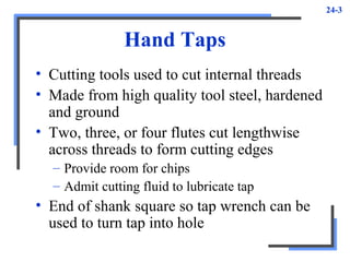
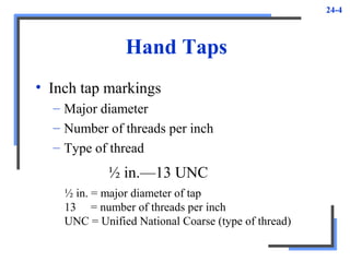
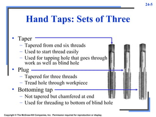
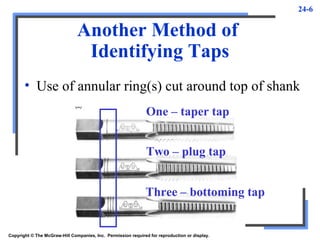
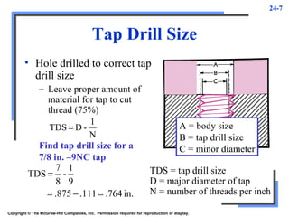
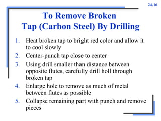
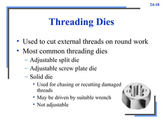
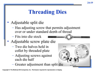
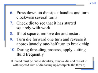
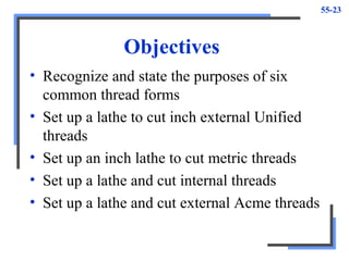
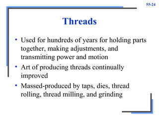
This document provides information about thread cutting tools and procedures. It discusses various types of taps used to cut internal threads, including hand taps, tap sizes and sets of taps. It also discusses tap drill sizes, how to tap holes, and methods for removing broken taps. Additionally, it covers threading dies used to cut external threads and the procedures for using hand dies. The objectives are to understand thread cutting tools and processes for both internal and external threads in inch and metric systems.
This document discusses different types of jigs and fixtures used in manufacturing. It describes various elements of jigs like the jig body, feet, drill bush, and plate. It then lists and describes common types of jigs like boring jigs, drill jigs, and template jigs. It also discusses different types of fixtures like plate fixtures, angle plate fixtures, vice-jaw fixtures, and multi-station fixtures. Finally, it covers fixtures for specific machine operations like turning, milling, boring, and welding fixtures.
This document discusses the geometry of plain milling cutters and twist drills. It describes the key features of milling cutters such as radial rake angle, radial relief angle, land, and lip angle. It also explains different types of milling operations including up milling, down milling, string milling, and gang milling. For twist drills, it outlines the drill point, twist drill nomenclature, and recommended drill geometries for different materials. Equations are provided for estimating drilling forces based on drill diameter and feed rate.
MACHINING OPERATIONS AND MACHINE TOOLS
Methods of Holding the Work in a Lathe (Chuck,Collet,face Plate,Holding the Work Between Centers)
Work Holding for Drill Presses
Boring Drilling, Reaming, Tapping Milling
Peripheral Milling vs. Face Milling
Shaper and Planer
Broaching
Jigs and fixtures are production tools used to accurately manufacture duplicate and interchangeable parts when large numbers are required. Jigs are guiding devices that locate and hold workpieces for machining, while fixtures are holding devices that attach to machines for quick, consistent locating, supporting, and clamping of blanks. Common jig types include plate jigs, box jigs, and indexing jigs. Common fixture types are plate fixtures, angle plate fixtures, and multistation fixtures. The main advantages of using jigs and fixtures are increased productivity, interchangeability of parts, uniform quality, reduced skill requirements, and lower costs.
Jigs and fixtures are production tools used to accurately manufacture duplicate parts. Jigs guide cutting tools and locate/support workpieces, while fixtures only locate/support workpieces. There are different types of jigs and fixtures for various machining operations like drilling, milling, and turning. Key factors in jig and fixture design include rigidity, chip control, workpiece support/location, and material selection to withstand cutting forces. Construction involves mechanical assembly using screws and dowels or combinations of welding and assembly.
This document discusses different types of cutting tool materials and their properties. It covers seven main types of toolbit materials including high-speed steel, cast alloys, cemented carbides, ceramics, cermets, cubic boron nitride and polycrystalline diamond. The key properties for cutting tools are hardness, wear resistance, shock resistance, shape/configuration. Cemented carbides are widely used and offer high hardness, wear resistance and can operate at high speeds without losing sharpness. Coatings like titanium carbide and nitride and aluminum oxide are used to improve wear resistance at different speeds. Tool geometry including side relief, side clearance, rake angles and nose radius are also covered.
This document discusses tapping and threading. It begins by explaining the objectives of learning about tapping processes and tools. It then defines tapping as the process of cutting threads using specific tools. It discusses taper, plug, and bottoming taps for starting and finishing threads. It also covers tap types, drill sizes, wrenches, and best practices for safe and effective tapping.
- Drill bushes are used to guide tools like drills and reamers and are made of hardened steel.
- There are different types of bushes including press fit, removable, and special bushes. Press fit bushes provide long life while guiding tools. Removable bushes like renewable and slip bushes allow for replacement of worn bushes. Special bushes can have unique shapes to prevent tool deflection.
- Drill bushes may have collars to control hole depth or be headless. Renewable bushes are replaced through a liner bush while slip bushes provide quick changeover between operations. Threaded and plate bushes can accommodate closely spaced holes.
This document provides an overview of milling and turning operations. It discusses the principles and types of milling machines like horizontal and vertical mills. Common milling operations include plain, face, side, profile, end and gang milling. Turning operations covered are facing, parting, grooving, boring, knurling, drilling, reaming, threading, taper and polygonal turning. Both milling and turning remove material using rotary cutters or single point tools on workpieces mounted on machine tools.
The document provides an introduction to machine design and the general considerations involved in designing machine components. It discusses the classification of machine designs, the general procedure for machine design, and considerations like the type of loads, material selection, motion of parts, and safety. It also summarizes the commonly used engineering materials and their important physical and mechanical properties that influence material selection for machine design.
The document describes the parts and functions of an indexing or dividing head used on milling machines. The indexing head allows the precise rotation of a workpiece to cut complex shapes. It consists of a headstock, index plates, gears, and other components. There are several methods for indexing including direct, simple, angular, and differential indexing. Direct indexing uses numbered slots or holes to rotate the workpiece a set number of divisions. Simple indexing uses gears and a crank to rotate the workpiece a calculated fraction of a turn.
Forging is the operation where the metal is heated and then a force is applied to manipulates the metals in such a way that the required final shape is obtained.
This document discusses tolerances and limits in engineering. It explains that components are made within tolerances due to manufacturing variability. There is an acceptable tolerance zone between the upper and lower limits for a component's dimensions. Various types of fits between parts are classified based on the overlap of their tolerance zones, including clearance fits, transition fits, and interference fits. International tolerance grades define standard tolerance zones using numerical designations.
This document provides an overview of metal cutting theory and processes. It discusses orthogonal and oblique cutting, types of cutting tools including single point and multipoint tools, tool geometry and signatures. It also covers mechanics of metal cutting including shear angle and chip formation, tool materials, tool wear and tool life, factors affecting machining, and types of metal cutting processes and chips. Cutting fluid types and applications are also summarized.
Location and locating devices used in jigs and fixturesAmruta Rane
This document discusses various principles and methods of locating workpieces in fixtures. It begins by defining what is meant by location and discusses the six degrees of freedom a workpiece has. It then covers different types of locating from plane surfaces using buttons, pins, pads and adjustable supports. It also discusses locating from profiles, cylinders, and preventing issues like redundant location and jamming. A variety of locating methods and components are presented, including dowel pins, nests, and sights. The document provides guidance on selecting locating methods based on workpiece and operation requirements.
The document discusses drilling and provides objectives about drilling machines. It defines drilling as cutting holes in metal using a drill and rotating motion. It identifies the parts of a drilling machine like the drive, table, and spindle. It describes different types of drills, reamers, and drilling machines. It lists safety precautions like securely clamping the workpiece and using correct drilling speeds.
This chapter aims to provide basic backgrounds of different types of machining processes and highlights on an understanding of important parameters which affects machining of metals with their chip removals.
Metal cutting or Machining is the process of producing workpiece by removing unwanted material from a block of metal. in the form of chips. This process is most important since almost all the products get their final shape and size by metal removal. either directly or indirectly.
The major drawback of the process is loss of material in the form of chips. In this chapter. we shall have a fundamental understanding of the basic metal process.
This presentation contains various aspects of metal cutting like mechanics of chip formation, single point cutting tool, chip breakers, types of chips,etc
The document discusses different types of turning fixtures and mandrels used to securely hold workpieces for machining operations on lathes. Turning fixtures are cheaper than milling and allow for asymmetric jobs to be machined. Fixtures must be carefully designed for operator safety, accuracy, and proper clamping to the faceplate. Mandrels are used internally to locate cylindrical workpieces and come in tapered, clamping, expanding, and threaded varieties to suit a range of bore sizes and provide accurate concentricity.
A reamer is a rotary cutting tool used to enlarge a previously drilled or bored hole to a high degree of accuracy and smooth finish. Reamers are made from heat treated steels or hard materials like tungsten carbide and diamond. There are various types of reamers including straight, hand, machine, rose, shell, tapered, and combination reamers. Reaming is performed on a lathe by mounting the workpiece and drilling or boring the hole slightly undersized, then mounting the reamer and slowly feeding it into the hole while applying cutting fluid to enlarge the hole to the final size.
The document discusses jigs and fixtures, which are tools used to precisely locate and secure workpieces during manufacturing operations like machining. It defines jigs and fixtures, describes their key elements and principles of location and clamping. It also covers different types of locating and clamping devices as well as common types of jigs like drilling jigs. Jigs are used to guide cutting tools, while fixtures only position and hold the workpiece. Together, jigs and fixtures help improve accuracy, interchangeability and efficiency of mass production.
This document discusses cutting temperature in machining. It outlines sources of heat generation during cutting including plastic deformation and friction. High temperatures can cause rapid tool wear, thermal damage to the workpiece, and residual stresses. Measuring temperature helps assess machinability, select cutting tools and fluids, and analyze temperature distribution. Important parameters include shear zone temperature, chip-tool interface temperature, and work-tool interface temperature. Both analytical and experimental methods are used to measure temperature, such as tool work thermocouples, moving thermocouples, and infrared techniques. Varying machining parameters impacts cutting temperature.
The one of the major part of CNC Machine is Cutting tools or Inserts. We need to study the Cutting tools and its nomenclature throughly and also study the materials of Cutting tools and types of tools. The Cutting tools are used to remove unwanted materials in the workpiece and to provide a good finish for a customers need.So the Cutting tools is very important to CNC Machine, if there is no cutting tool in CNC Machine, there is no CNC Machine. So the cutting tools are very important to all CNC Machines
This document provides definitions and principles related to locating and clamping in jigs and fixtures design. It defines a jig as a device that holds work and locates the tool path, and a fixture as a device that locates work on a machine table. It discusses locating principles like six point location and 3-2-1 principle. It also covers various locating and clamping devices like pins, buttons, V-locators, and different types of clamps. The document aims to provide fundamental guidelines for effective design of jigs and fixtures.
This document provides information about CNC milling. It discusses learning outcomes, introduces milling processes and classifications. It describes the theory of CNC milling machines, including their characteristics, geometry, coordinate systems, zero and reference points, and programming structure. It also covers cutting values, clamping devices, and lists G-codes and M-functions.
education is a key for everything so the objective of this slide is to share knowledge to the glob in my area of specialization.
This lecture note is basically designed for mechanical Engineering Manufacturing stream students and Instructors.
The document discusses various threading tools and procedures. It covers different types of taps such as taper, plug, and bottoming taps. It also discusses tap drill sizes, threading dies, and machine screws. Common thread standards covered include American National and Metric systems. Proper techniques are outlined for tapping holes and using dies.
1) Screw threads are commonly used for fastening parts together, clamping objects, transmitting motion and power, and making precision measurements of length.
2) There are various methods for manufacturing screw threads, including machining using lathes and taps, thread milling, rolling, and grinding.
3) Thread manufacturing methods are chosen based on factors such as the required accuracy, material properties, batch size, and thread specifications. Machining is suitable for high accuracy threads while rolling is faster but provides less accuracy.
This document provides information on threading operations for mechanical engineering technology students. It defines threading terminology like major diameter, minor diameter, crest, root, flank, pitch and lead. It describes the two main categories of threads - external and internal - and different types of threads. It explains how to cut threads using taps and dies by hand as well as on a lathe, outlining the steps and safety precautions for each method. The goal is for students to understand threading concepts and processes.
The document discusses various thread terminology and types of threads. It defines common thread terminology such as major diameter, minor diameter, pitch, lead, and thread angles. It also describes several common thread forms including ISO metric, American National, British Standard, Unified, Acme, and square threads. It provides details on thread fits, classifications, tolerances and how to calculate thread properties.
This document discusses various methods for cutting screw threads, including:
1. Using a lathe to cut threads by securing a 60° threading toolbit and setting the compound rest at 29° to cut the thread along the workpiece.
2. Using a thread milling cutter that is tilted at the helix angle of the thread or a multiple-form cutter parallel to the workpiece to cut the thread in one revolution.
3. Grinding threads using a single-profile or multi-profile grinding wheel to cut internal or external threads.
4. Rolling threads using plunge or traverse dies on a die machine to shape the thread without removing material.
This presentation gives the information about Screw thread measurements and Gear measurement of the subject: Mechanical measurement and Metrology (10ME32/42) of VTU Syllabus covering unit-4.
Thread cutting is a lathe operation that produces helical threads on cylindrical workpieces using a tool with the same shape as the thread. There are different types of screw threads and thread nomenclature. Lathe setting for thread cutting involves introducing a translating gear, where the gear ratio equals the pitch of the workpiece divided by the pitch of the lead screw, which can be expressed as 5 times the number of threads per inch divided by 127, where 5 is the progression and the number of threads per inch is the reciprocal of the pitch. Lathe speeds are measured in revolutions per minute and can be changed using stepped pulleys, gear levers, changing belts on belt-driven lathes, or moving speed levers on
Type of threads - How to identify threadsTeesing BV
This document provides information about different types of threads, including metric (M), BSPP, BSPT, NPT, UNC, and UNF threads. It discusses the key characteristics that define each type of thread such as diameter, pitch, taper angle, and flank angle. Examples are given for various common thread sizes of each type. In addition, the document addresses frequently asked questions about identifying threads, determining if threads are tapered or parallel, differences between BSPP and BSPT, thread sealing, and thread compatibility.
This document provides information on cutting internal screw threads. It defines internal screw threads and explains that taps are used to cut internal threads. Taps are made of carbon steel or high-speed steel and are carefully hardened and tempered. Taps come in three types - taper, second, and plug taps. The document outlines the steps for cutting internal threads, including calculating the proper tap drill size and using taps in the correct order. It stresses taking care when tapping, such as starting the tap squarely and removing chips, to avoid damaging the fragile taps.
1. The document describes the steps for cutting external and internal threads on a lathe. It discusses setting up tools and workpieces and taking incremental cuts to form threads of the desired pitch and depth.
2. Key steps include setting spindle speed and gearing, mounting and centering the workpiece, establishing a zero position for the tool, and using the cross-slide, compound slide, and half-nuts to take successive cuts along the workpiece.
3. The document also covers techniques for left-hand threads, tapered threads, metric threads on an inch machine, and internal threading using boring bars or single-point tools.
Harvey Tool manufactures several types of thread milling cutters for internal and external threading. Their single form cutters can machine any pitch thread in hardened steels up to 68Rc. Their multi-form cutters are designed for maximum chip ejection, deep threading applications, cutting National Pipe Taper threads, UN threads, and metric threads. The cutters are available in various coatings and styles to machine a wide range of thread types and sizes in various materials.
Harvey Tool produces various types of keyseat cutters for milling keyways and retaining ring grooves. They are available in small and large diameters down to 1/16 inches, with multiple radial depths of cut and flute styles. Features include dished sides for clearance, corner radii for strength, and staggered tooth or full radius designs for improved chip evacuation and surface finish. Cutters are offered for standard materials as well as non-ferrous alloys like aluminum. Retaining ring groove cutters are optimized for common retaining ring sizes per standards.
This document provides an overview of pneumatic symbols used in system diagrams and component identification. It includes standards for the symbols, basic shapes used to construct the symbols, common functional elements, flowlines and connections, conditioning components, pressure control devices, actuators including cylinders and valves, and details on valve symbol structure. The document is intended as a reference for understanding pneumatic circuit diagrams and component schematics.
The document discusses thread rolling, including:
- Thread rolling strengthens material without cutting, lowering costs and speeds production.
- Proper material selection, tooling, speeds and feeds, and gaging are required for quality threads.
- Common issues like slivers, incorrect pitch, and mismatched helix angles can be avoided through optimization of rolling conditions, tool synchronization, and material selection.
The document discusses different types of threaded fasteners including bolts, studs, screws, and set screws. It defines threaded fastener terminology such as external and internal threads, major and minor diameters, pitch, and thread forms. It also provides steps for drawing representations of various threaded fasteners and holes.
The following presentation consists of a brief introduction to power screw that we use in our day to day life, its types, analysis of load, efficiency, application and examples with images.
The document summarizes the principle parts and operations of a lathe machine. It describes how the lathe holds workpieces between centers or in a chuck to rotate them while a cutting tool is fed against the workpiece. It then explains the main components of a lathe including the bed, headstock, spindle, carriage, saddle, cross-slide, compound, toolpost and tools. It also covers different types of lathes and work holding devices as well as common lathe operations like turning, facing, boring and threading.
Fundamentals of Metal cutting and Machining Processes
MACHINING OPERATIONS AND MACHINING TOOLS
Turning and Related Operations
Drilling and Related Operations
Milling
Machining Centers and Turning Centers
Other Machining Operations
High Speed Machining
The document discusses lathe machines. It defines a lathe as a machine that removes metal from a workpiece to shape it. It then describes some key parts of a lathe like the bed, headstock, tailstock, and carriage. It explains the working principle of a lathe where the cutting tool is fed into a rotating workpiece to shape it. Finally, it summarizes some common lathe operations like turning, facing, drilling and threading.
Rolling is a metal forming process that uses rolls to reduce the thickness and increase the length of metal workpieces. It can be done hot or cold. Hot rolling occurs above the metal's recrystallization temperature and results in a more uniform structure, while cold rolling occurs at room temperature and produces closer tolerances and a better surface finish. The document defines various products of rolling like billets, blooms, slabs, plates, sheets and strips based on their dimensions. It also describes different types of rolling processes like continuous, transverse, shape, ring and thread rolling as well as the types of mills used like two-high, three-high and four-high mills.
Lathe machine parts construction and opperationsAkash756513
The document discusses different types of lathes and their parts and operations. It describes the engine lathe as the most versatile and accurate lathe, used for turning, tapering, threading and other operations. It also discusses turret lathes, which are used for mass production of duplicate parts and have multiple tool holders. The document outlines common lathe sizes based on swing diameter and distance between centers. It provides details on various lathe accessories such as chucks, centers, and tool holders. Finally, it covers cutting speeds, feeds, and depths of cut for different materials.
The document discusses different types of lathes and their components and operations. It describes the key parts of a centre lathe like the headstock, tailstock, bed, and carriage. It explains different lathe operations such as turning, facing, boring, drilling, threading and knurling. The document also discusses various methods of taper turning and thread cutting on lathes. Special attachments for centre lathes are mentioned as well to enable additional machining capabilities.
This document discusses the history and types of lathes. It describes the engine lathe as the basic lathe found in school shops and toolrooms for turning, tapering, threading and other operations. The turret lathe is used for producing duplicate parts and has a multisided toolpost to employ different cutting tools in sequence. Lathe size is designated by swing diameter and distance between centers, with common sizes ranging from 9-30 inches swing and up to 12 feet between centers. Accessories like chucks, centers, and toolholders are also described.
This document provides an overview of workshop safety and tools. It discusses general safety measures like proper attire, eye protection and keeping the floor clear. It also describes common causes of accidents like improper attitude, failure to recognize dangers and strong emotions. Personal safety equipment is outlined like safety goggles, shoes and gloves. Measuring tools including tape measures, calipers and micrometers are defined. Various hand tools for marking, cutting and holding materials are presented. Processes for cutting internal and external threads with taps and dies are covered. Fundamentals of welding different joint types are briefly introduced.
Drill bits are cutting tools used to create cylindrical holes. They are held in a chuck and rotate to provide torque and force. Specialized bits can create non-cylindrical holes. Common drilling operations include reaming to enlarge holes, tapping to cut internal threads, counterboring, and countersinking. Twist drill bits are the most commonly used type and have a cylindrical shaft and helical flutes.
This chapter discusses the essential hand tools used by plumbers. It identifies common tools such as tape measures, levels, screwdrivers, pliers, wrenches, hammers, saws, snips, knives, chisels, and specialty tools for working with copper, plastic, and cast iron piping. The chapter emphasizes that hand tools are necessary for both new installation and repair work. It also stresses the importance of safety and using personal protective equipment when working with tools.
Nota berkaitan dengan kaedah drilling untuk sem 1qhairulshafiq
The document discusses drilling operations and drill bits. It defines the parts of a drill bit including the point, shank, body, flutes, and angles. It explains how drill sizes are stated based on factors like shank type, flute type, length, and application. The document also covers how to mark out for drilling, methods of holding drill bits, calculating spindle speed and feed rate, types of coolants, and safety procedures. It discusses work holding devices for drilling like v-blocks and different types of drilling jigs.
This document provides information on drilling basics and drill components. It discusses the history and evolution of drills from primitive drills used by Native Americans to modern twist and indexable drills. Key components of drills are described such as the point, helix, lip clearance, web thickness, chisel edge, land, and margins. Factors that influence drill selection and performance are also covered like drill point geometry, helix angle, clearance, speeds, feeds, forces, coolant delivery, and failure modes.
This document provides lecture notes on workshop practice II, covering drilling operations and welding processes. It discusses drilling machine types, drilling geometry, cutting conditions, feed and speed, operations like drilling and reaming. It also covers welding principles like fusion and pressure welding, classification into oxy-acetylene, shielded metal arc, MIG and TIG welding. Key details are provided on welding processes, inert gas shielding, and consumable electrodes.
The document provides information on operations that can be performed on a vertical milling machine. It discusses aligning the vertical head to be square to the table within ±0.001 in. by using a dial indicator. It also describes inserting and removing end mills from spring collets and accurately machining a block square and parallel as well as drilling holes to a precise location. The document contains objectives, descriptions of parts of ram-type vertical mills, and discussions of cutting speed, feed, depth of cut, and end mills.
This document discusses different types of fasteners used in automotive applications. It describes threaded fasteners like bolts, screws, and studs which are sized using either the U.S. customary or metric systems. Non-threaded fasteners like snap rings, keys, and rivets are also discussed. The document stresses the importance of using the correctly sized and graded fasteners, and properly torquing threaded fasteners. Electrical wiring and connectors are also covered.
Threaded fasteners such as bolts and screws join components together through the transformation of rotational motion into linear motion. There are various thread standards that specify attributes like diameter, pitch, class of fit, and thread type. Early threaded fasteners lacked standardization but efforts in the 18th-19th centuries established conventions for sizes. Modern standards include metric and unified external and internal thread systems.
Tapers are changes in diameter along an axis, expressed as taper per foot or ratio of millimeters per unit length. There are three main methods to turn tapers on a lathe: offsetting the tailstock, using a taper attachment, or adjusting the compound rest angle. A taper attachment allows quick setup changes and a wider range of tapers than offsetting the tailstock. Internal and external tapers can be machined using plug gages and adjusting the taper attachment or compound rest angle.
The document discusses drilling machines and drilling operations. It describes the main components and functions of drilling machines like bench drilling machines and radial drilling machines. It explains drilling tool components like drill bits and twist drills. It also covers other drilling operations like reaming, boring, counterboring, countersinking, spot facing and tapping that can be done on drilling machines. Safety precautions for operating drilling machines are also mentioned.
The document discusses various methods for manufacturing gears and threads. It describes casting, metal forming, powder metallurgy, and metal removal as common methods for making gears. Metal forming techniques include roll forming, extrusion, stamping, and coining. Metal removal techniques involve gear cutting, shaping, planing, hobbing, and broaching. The document also outlines various threading manufacturing methods such as lathe cutting, chasing, die threading, tapping, milling, rolling, grinding, casting, and whirling.
gear and thread manufacturing,metal cutting,manufacturing processes,Productio...Prof.Mayur Modi
The document discusses various methods for manufacturing gears and threads. It describes casting, metal forming, powder metallurgy, and metal removal as common methods for making gears. Metal forming techniques include roll forming, extrusion, stamping, and coining. Metal removal techniques involve gear cutting, shaping, planing, hobbing, and broaching. The document also outlines various threading manufacturing methods such as lathe cutting, chasing, die threading, tapping, milling, rolling, grinding, casting, and whirling.
Drilling, boring reaming operation on latheAliRaza1767
The document discusses drilling, boring, and reaming machine tools and processes. It describes how drilling uses a drill bit to cut a circular hole through rotation, with the material removed via shearing and extrusion. Different materials are used for drill bits depending on the workpiece material. Boring enlarges existing holes, while reaming finishes holes by making the surface smooth. Potential troubleshooting issues for drilling include insufficient torque/power, hole asymmetry, tool wear, and vibrations.
MILLING – Cutting parameters, machine time calculation
Milling operation – Plain milling, side & face milling, form milling, gang milling, end milling, face milling, T slot milling, slitting
GEAR CUTTING – Gear cutting on milling machine – dividing head and indexing method, gear hobbing, principle of operation, advantages & limitation, hobbing tech, gear shaping, gear finishing process
This document provides an overview of power generation in India. It discusses the various types of power plants used in India including thermal, hydro, nuclear, solar, wind, etc. It outlines the installed capacity, energy generation, supply and demand gap, per capita consumption, and load factor of India's power sector. Maps show the distribution of energy resources and load centers across India. The development of India's electricity industry over the last 50 years is summarized. Factors influencing the selection of turbines for power plants like head variation, load variation, and specific speed are also discussed.
The document provides an overview of fuel cell technology. It discusses the brief history of fuel cells and the basic principles of electrolysis and how fuel cells work by reversing the electrolysis process. It describes the main components of a fuel cell and the five most common types: alkaline, molten carbonate, phosphoric acid, proton exchange membrane, and solid oxide fuel cells. The benefits of fuel cells are highlighted such as efficiency, reliability and fuel flexibility. Challenges for different fuel cell types are also summarized, for example high operating temperatures of solid oxide fuel cells can limit applications.
The document describes how to use a Vernier caliper to accurately measure diameter, thickness, depth, and other linear dimensions. It explains the different parts of the Vernier caliper including the inside jaws, outside jaws, Vernier scale, and main scale. It provides instructions on how to measure internal diameter, external diameter, and depth using the appropriate jaws or depth gauge. It also describes how to read the Vernier scale to obtain a more precise measurement than the main scale alone by looking for the coinciding Vernier and main scale divisions. An example measurement is given and the accurate reading is calculated.
The document provides instructions for using a Lenovo IdeaPad laptop. It advises reading safety manuals before use and notes that features may vary by model. It also contains chapters on getting to know the computer, starting Windows 8, troubleshooting, and replacing components. Instructions are applicable to several Lenovo IdeaPad models unless otherwise stated.
This document provides guidance on improving presentation skills. It discusses the importance of being able to clearly express ideas to others. While content is important, delivery is also key. The document outlines best practices for using eye contact, body language, voice, preparing content using the 3 A's framework of understanding your Audience, defining the desired Action, and arranging the Argument. It also covers developing effective visual aids and responding well to questions. The overall aim is to help presenters feel more confident and make presentations that engage audiences.
This document provides a list of 30 important questions related to elements of electrical engineering. The questions cover various topics including Kirchhoff's laws, capacitors, inductors, magnetic circuits, transformers, ac circuits and measurements. Some of the key topics covered are:
- Kirchhoff's voltage and current laws and their applications to DC and AC circuits
- Definitions and derivations related to capacitance, inductance, magnetic fields and circuits
- Explanations of self and mutual induction, transformers, ac circuits and power measurements
- Diagrams of various electrical components and circuits like RL, RC circuits and phasor diagrams.
Magnetic recording leaves patterns of magnetization on magnetic media to store data. Tracks are formed as the read/write head passes over the media. There are three main orientations for magnetization: longitudinal, perpendicular, and lateral. Longitudinal recording uses a ring-shaped electromagnet head with a gap to magnetize the media as it moves under the head. Changes in the current passing through the head leave spatial variations in magnetization along the track. Modern drives use magneto-resistive read heads that directly sense the magnetic flux from the tracks. Error correcting codes and redundant data help ensure reliable storage despite defects and noise sources that can cause errors.
This document provides an overview of different types of computer memory devices. It begins by explaining the importance of memory and then outlines the main types which include main memory (RAM and ROM), cache memory, and secondary storage devices. RAM is further divided into DRAM and SRAM. ROM includes PROM, EPROM, and EEPROM. Secondary storage includes magnetic devices like hard disks and floppy disks, as well as optical devices like CDs and DVDs. Newer memory technologies like flash memory and Blu-ray disks are also mentioned.
The document provides an overview of the Aston Martin DB9 sports car. It describes the DB9 as a high-performance grand tourer that combines beauty and functionality. It has a powerful 6.0-liter V12 engine that provides exceptional power and acceleration while also being refined. The DB9 is designed to be a supremely capable sports car with luxury and comfort for long distance driving. Both the coupe and convertible models prioritize driver involvement, character, and stirring the soul with their power, performance, and unique sound.
This document lists and describes the original Seven Wonders of the Ancient World as well as a newer list of New Seven Wonders of the World that was voted on. It includes locations like the Taj Mahal in India, the Great Wall of China, Machu Picchu in Peru, Petra in Jordan, and structures from several other countries. Links are provided for more information on some of the wonders.
There are four main barriers to effective communication: process barriers related to the perceptual model, personal barriers involving individual competence and interpersonal dynamics, physical barriers regarding distance between communicators, and semantic barriers related to different understandings of words used. Effective communication also depends on listening styles like results-oriented, reasons-oriented, or process-oriented listening. Communication is an ongoing, dynamic, transactional process as shown in linear and transactional models, and it is impossible not to communicate, with communication occurring through intrapersonal, small group, mass, interpersonal, and public channels.
Introduction- e - waste – definition - sources of e-waste– hazardous substances in e-waste - effects of e-waste on environment and human health- need for e-waste management– e-waste handling rules - waste minimization techniques for managing e-waste – recycling of e-waste - disposal treatment methods of e- waste – mechanism of extraction of precious metal from leaching solution-global Scenario of E-waste – E-waste in India- case studies.
6th International Conference on Machine Learning & Applications (CMLA 2024)ClaraZara1
6th International Conference on Machine Learning & Applications (CMLA 2024) will provide an excellent international forum for sharing knowledge and results in theory, methodology and applications of on Machine Learning & Applications.
DEEP LEARNING FOR SMART GRID INTRUSION DETECTION: A HYBRID CNN-LSTM-BASED MODELgerogepatton
As digital technology becomes more deeply embedded in power systems, protecting the communication
networks of Smart Grids (SG) has emerged as a critical concern. Distributed Network Protocol 3 (DNP3)
represents a multi-tiered application layer protocol extensively utilized in Supervisory Control and Data
Acquisition (SCADA)-based smart grids to facilitate real-time data gathering and control functionalities.
Robust Intrusion Detection Systems (IDS) are necessary for early threat detection and mitigation because
of the interconnection of these networks, which makes them vulnerable to a variety of cyberattacks. To
solve this issue, this paper develops a hybrid Deep Learning (DL) model specifically designed for intrusion
detection in smart grids. The proposed approach is a combination of the Convolutional Neural Network
(CNN) and the Long-Short-Term Memory algorithms (LSTM). We employed a recent intrusion detection
dataset (DNP3), which focuses on unauthorized commands and Denial of Service (DoS) cyberattacks, to
train and test our model. The results of our experiments show that our CNN-LSTM method is much better
at finding smart grid intrusions than other deep learning algorithms used for classification. In addition,
our proposed approach improves accuracy, precision, recall, and F1 score, achieving a high detection
accuracy rate of 99.50%.
Adaptive synchronous sliding control for a robot manipulator based on neural ...IJECEIAES
Robot manipulators have become important equipment in production lines, medical fields, and transportation. Improving the quality of trajectory tracking for
robot hands is always an attractive topic in the research community. This is a
challenging problem because robot manipulators are complex nonlinear systems
and are often subject to fluctuations in loads and external disturbances. This
article proposes an adaptive synchronous sliding control scheme to improve trajectory tracking performance for a robot manipulator. The proposed controller
ensures that the positions of the joints track the desired trajectory, synchronize
the errors, and significantly reduces chattering. First, the synchronous tracking
errors and synchronous sliding surfaces are presented. Second, the synchronous
tracking error dynamics are determined. Third, a robust adaptive control law is
designed,the unknown components of the model are estimated online by the neural network, and the parameters of the switching elements are selected by fuzzy
logic. The built algorithm ensures that the tracking and approximation errors
are ultimately uniformly bounded (UUB). Finally, the effectiveness of the constructed algorithm is demonstrated through simulation and experimental results.
Simulation and experimental results show that the proposed controller is effective with small synchronous tracking errors, and the chattering phenomenon is
significantly reduced.
2. 24-2
Objectives
• Calculate the tap drill size for inch and
metric taps
• Cut internal threads using a variety of taps
• Know the methods used to remove broken
taps from a hole
• Cut external threads using a variety of dies
3. 24-3
Hand Taps
• Cutting tools used to cut internal threads
• Made from high quality tool steel, hardened
and ground
• Two, three, or four flutes cut lengthwise
across threads to form cutting edges
– Provide room for chips
– Admit cutting fluid to lubricate tap
• End of shank square so tap wrench can be
used to turn tap into hole
4. 24-4
Hand Taps
• Inch tap markings
– Major diameter
– Number of threads per inch
– Type of thread
½ in.—13 UNC
½ in. = major diameter of tap
13 = number of threads per inch
UNC = Unified National Coarse (type of thread)
8. 24-8
Metric Taps
• Several thread forms and standards in metric
thread system
• International Standards Organization (ISO)
has adopted standard metric thread
– Will be used in US, Canada and other countries
– Have only 25 thread sizes (1.6 to 100 mm)
• Available in sets of three: taper, plug and
bottoming taps
– Identified by letter M followed by nominal
diameter of thread in mm times pitch in mm
9. 24-9
Tap Drill Sizes for Metric Taps
Tap drill size for metric taps calculated in same
manner as for U.S. Standard threads
TDS = major diameter (mm) – pitch (mm)
Example:
Find the tap drill size for a 22 – 2.5 mm thread
TDS = 22 – 2.5
= 19.5 mm
10. 24-10
Tapping a Hole
• Operation of cutting internal thread using
tap and tap wrench
• Taps hard and brittle
• Easily broken
– Extreme care used to prevent breakage
– Broken tap in hole difficult to remove and
often results in scrapping work
11. 24-11
To Tap Hole By Hand
1. Select correct taps and tap wrench for job
2. Apply suitable cutting fluid to the tap
• No fluid required for tapping brass or cast iron
1. Place tap in hole as vertically as possible;
press downward on wrench, applying equal
pressure on both handles; turn clockwise
(for right-hand thread) for two turns
12. 24-12
4. Remove tap wrench and check tap for
squareness
• Check two positions at 90º to each other
4. If tap not entered squarely, remove from
hole and restart it by applying pressure in
direction from which tap leans
5. When tap properly started, feed it into
hole by turning tap wrench
6. Turn tap clockwise one-quarter turn, and
turn it backward about ½ turn to break the
chip (must turn with steady motion)
13. 24-13
Removing Broken Taps
• Several methods may be used to remove
broken tap (some successful, others not!)
– Tap Extractor
• Tool with four fingers that slip into flutes of broken
tap; wrench fitter to extractor and turned to extract
– Drilling
• Drill through broken tap
– Acid Method
• Acid acts on steel and loosens tap for extraction
– Tap Disintegrators
• Uses electrical discharge principle to cut through tap
14. 24-14
To Remove Broken Tap Using a
Tap Extractor
1. Select proper size extractor for tap
2. Slide collar, to which fingers attached,
down body so fingers project well below
end of body
3. Slide fingers into flutes of broken tap,
making sure they go down into hole as far
as possible
15. 24-15
4. Slide body down until it rests on top of
broken tap
• Give maximum support to fingers
4. Slide collar down until it rests on top of
work
• Also provides support for fingers
4. Apply wrench to square end of body top
5. Turn wrench gently in counterclockwise
direction
Note: Do not force extractor – will damage fingers
16. 24-16
To Remove Broken
Tap (Carbon Steel) By Drilling
1. Heat broken tap to bright red color and allow it
to cool slowly
2. Center-punch tap close to center
3. Using drill smaller than distance between
opposite flutes, carefully drill holl through
broken tap
4. Enlarge hole to remove as much of metal
between flutes as possible
5. Collapse remaining part with punch and remove
pieces
17. 24-17
To Remove Broken Tap (High-
speed Steel) Using the Acid Method
1. Dilute one part nitric acid with five parts
water
2. Inject mixture into hole; acid will act on
steel and loosen tap
3. Remove tap with extractor or pliers
4. Wash remaining acid from thread with
water to neutralize acid
18. 24-18
Threading Dies
• Used to cut external threads on round work
• Most common threading dies
– Adjustable split die
– Adjustable screw plate die
– Solid die
• Used for chasing or recutting damaged
threads
• May be driven by suitable wrench
• Not adjustable
20. 24-20
To Thread With a Hand Die
1. Chamfer end of workpiece with file or on
grinder
2. Fasten work securely in vise
3. Select proper die and die stock
4. Lubricate tapered end of die with suitable
cutting lubricant
5. Place tapered end of die squarely on
workpiece
21. 24-21
6. Press down on die stock handles and turn
clockwise several turns
7. Check die to see that it has started
squarely with work
8. If not square, remove die and restart
9. Turn die forward one turn and reverse it
approximately one-half turn to break chip
10. During threading process, apply cutting
fluid frequently
If thread must be cut to shoulder, remove die and restart it
with tapered side of die facing up (complete the thread)
23. 55-23
Objectives
• Recognize and state the purposes of six
common thread forms
• Set up a lathe to cut inch external Unified
threads
• Set up an inch lathe to cut metric threads
• Set up a lathe and cut internal threads
• Set up a lathe and cut external Acme threads
24. 55-24
Threads
• Used for hundreds of years for holding parts
together, making adjustments, and
transmitting power and motion
• Art of producing threads continually
improved
• Massed-produced by taps, dies, thread
rolling, thread milling, and grinding
25. 55-25
Threads
• Thread
– Helical ridge of uniform section formed on
inside or outside of cylinder or cone
• Used for several purposes:
– Fasten devices such as screws, bolts, studs, and
nuts
– Provide accurate measurement, as in micrometer
– Transmit motion
– Increase force
27. 55-27
Thread Terminology
• Screw thread
– Helical ridge of uniform section formed on
inside or outside of cylinder or cone
• External thread
– Cut on external surface or cone
• Internal thread
– Produced on inside of cylinder or cone
29. 55-29
Thread Forms
• April, 1975 ISO came to an agreement
covering standard metric thread profile
– Specifies sizes and pitches for various threads
in new ISO Metric Thread Standard
– Has 25 thread sizes, range in diameter from 1.6
to 100 mm
– Identified by letter M, nominal diameter, and
pitch M 5 X 0.8
31. 55-31
American National Standard Thread
• Divided into four main series, all having
same shape and proportions
– National Coarse (NC)
– National Fine (NF)
– National Special (NS)
– National Pipe (NPT)
• Has 60º angle with root and crest truncated
to 1/8th
the pitch
• Used in fabrication, machine construction
40. 55-40
Thread Fits and Classifications
• Fit
– Relationship between two mating parts
– Determined by amount of clearance or
interference when they are assembled
• Nominal size
– Designation used to identify size of part
• Actual size
– Measured size of thread or part
– Basic size: size from which tolerances are set
41. 55-41
Allowance
• Permissible difference between largest
external thread and smallest internal thread
• Difference produces tightest fit acceptable
for any given classification
The allowance for a 1 in.—8 UNC Class 2A and 2B fit is:
Minimum pitch diameter of the
internal thread (2B) = .9188 in.
Maximum pitch diameter of the
external thread (2A) = .9168 in.
Allowance = .002 in.
42. 55-42
Tolerance
• Variation permitted in part size
• May be expressed as plus, minus, or both
• Total tolerance is sum of plus and minus tolerances
• In Unified and National systems, tolerance is plus
on external threads and minus on internal threads
Maximum pitch diameter of the
external thread (2A) = .9168 in.
Minimum pitch diameter of the
external thread (2A) = .9100 in.
Tolerance = .0068 in.
The tolerance for a 1 in.—8 UNC Class 2A thread is:
43. 55-43
Limits
• Maximum and minimum dimensions of part
Maximum pitch diameter of the
external thread (2A) = .9168 in..
Minimum pitch diameter of the
external thread (2A) = .9100 in.
The limits for a 1 in.—8 UNC Class 2A thread are:
44. 55-44
Thread Calculations: Example 2
P = pitch = 1 mm
D = 0.54127 x 1
= 0.54 mm
What are the pitch, depth, minor diameter, width of crest
and width of root for an M 6.3 X 1 thread?
mm125.0
1x125.0
x.1250crestofWidth
mm22.5
.54)(.54-6.3
)(-diaMajordiaMinor
=
=
=
=
+=
+=
P
DD
mm25.0
1x0.25
x25.0rootofWidth
=
=
= P
45. 55-45
Procedure to Set the Quick-
Change Gearbox for Threading
1. Check drawing for thread pitch required
2. From chart on quick-change gearbox, find
whole number that represents pitch in
threads per inch or in millimeters
3. With lathe stopped, engage tumbler lever
in hole, which is in line with the pitch
4. Set top lever in proper position as
indicated on chart
46. 55-46
5. Engage sliding gear in or out as required
6. Turn lathe spindle by hand to ensure that
lead screw revolves
7. Recheck lever settings to avoid errors
48. 55-48
Procedure to Set Up a Lathe for
Threading (60º Thread)
1. Set lathe speed to ¼ speed used for turning
2. Set quick-change gearbox for required pitch
in threads per inch or in millimeters
3. Engage lead screw
4. Secure 60º threading toolbit and check
angle using thread center gage
5. Set compound rest at 29º to right; set to left
for left-hand thread
49. 55-49
6. Set cutting tool to height of lathe center
point
7. Mount work between centers
• Make sure lathe dog is tight on work
• If work mounted in chuck, it must be held
tightly
6. Set toolbit at right angles to work, using
thread center gage
7. Arrange apron controls to allow split-nut
lever to be engaged
50. 55-50
Thread-Cutting Operation
Procedure to cut a 60º thread
1. Check major diameter of work for size
2. Start lathe and chamfer end of workpiece
with side of threading tool to just below
minor diameter of thread
3. Mark length to be threaded by cutting
light groove at this point with threading
tool while lathe revolving
51. 55-51
4. Move carriage until point of threading tool
near right-hand end of work
5. Turn crossfeed handle until threading tool
close to diameter, but stop when handle is at
3 o'clock position
6. Hold crossfeed handle in this position and
set graduated collar to zero
7. Turn compound rest handle until threading
tool lightly marks work
52. 55-52
8. Move carriage to right until toolbit clears
end of work
9. Feed compound rest clockwise about .003 in.
10. Engage split-nut lever on correct line of
thread-chasing dial and take trial cut along
length to be threaded
11. At end of cut, turn crossfeed handle
counterclockwise to move toolbit away from
work and disengage split-nut lever
53. 55-53
12. Stop lathe and check number of tpi with
thread pitch gage, rule, or center gage
13. After each cut, turn carriage handwheel to
bring toolbit to start of thread and return
crossfeed handle to zero
14. Set depth of all threading cuts with
compound rest handle
• See Table 55.2 and Table 55.3
55. 55-55
Table 55.2 Depth settings for cutting 60°
national form threads*
Compound Rest Setting
tpi 0° 30° 29°
24 .027 .031 .0308
20 .0325 .0375 .037
18 .036 .0417 .041
16 .0405 .0468 .046
14 .0465 .0537 .0525
13 .050 .0577 .057
11 .059 .068 .0674
Portion of table taken
from textbook
56. 55-56
15. Apply cutting fluid and take successive
cuts until top (crest) and bottom (root) of
thread are same width
16. Remove burrs from top of thread with file
17. Check thread with master nut and take
further cuts
57. 55-57
Six Ways to Check Threads
• Depends on accuracy required:
1. Master nut or screw
2. Thread micrometer
3. Three wires
4. Thread roll or snap gage
5. Thread ring or plug gage
6. Optical comparator
58. 55-58
To Reset a Threading Tool
• Must reset when need to remove partly
threaded work from lathe, tool removed
for regrinding, or work slips under lathe
dog
Procedure
1. Set up lathe and work for thread cutting
2. Start lathe, toolbit clear of work, engage
split-nut lever on correct line
3. Allow carriage to travel until toolbit
opposite any portion of unfinished thread
59. 55-59
4. Stop lathe, leaving split-nut lever engaged
5. Feed toolbit into thread groove using only
compound rest and crossfeed handles until
right-hand edge of toolbit touches rear side
of thread
6. Set crossfeed graduated collar to zero
7. Back out threading tool using crossfeed
handle, disengage split-nut lever, and
move carriage until toolbit clears start of
thread
60. 55-60
8. Set crossfeed handle back to zero and take
trial cut without setting compound rest
9. Set depth of cut using compound rest
handle and finish thread to required depth
61. 55-61
Common Methods of
Measuring Threads
1. Thread ring gage
2. Thread plug gage
3. Thread snap gage
4. Screw thread micrometer
5. Optical comparator
6. Three-wire method
63. 55-63
To Calculate the
Measurement over the Wires
N
GDM
5155.1
3 −+=
where M = measurement over the wires
D = major diameter of the thread
G = diameter of the wire size used
N = number of tpi
Any of the following formulas can be used to calculate G:
P
N
P
N
P
N
.505or
.505
ireSmallest w
.57735or
.57735
wiresize-Best
1.010or
010.1
reLargest wi
=
=
=