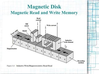
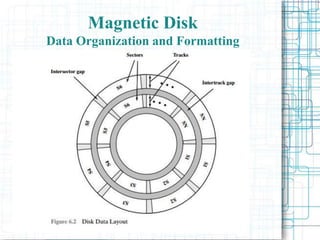
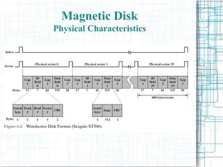
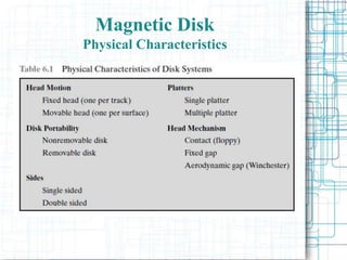
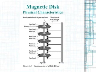
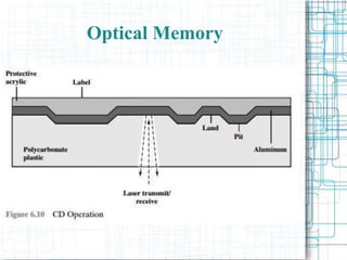
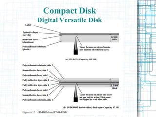
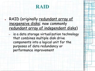
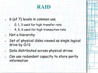
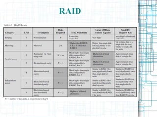
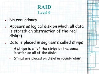
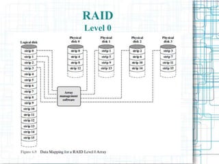
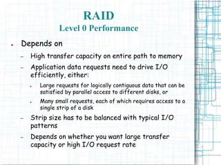
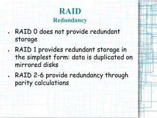
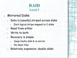
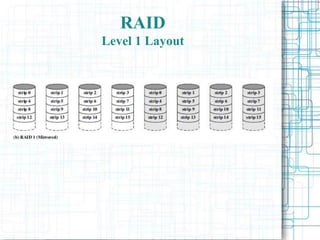
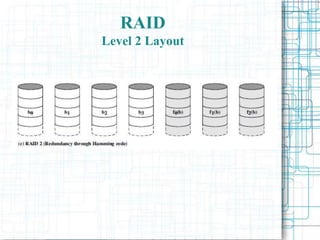
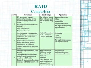
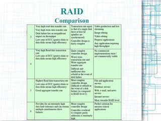
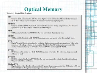
Magnetic disks remain the most important component of external memory. Data is recorded on disks through magnetic read and write heads. Disks are organized into tracks and sectors for efficient data access. RAID systems provide data redundancy or higher performance through striping and mirroring across multiple disks. Optical disks like CDs and DVDs store data through microscopic pits and lands read by lasers, and use constant linear velocity to increase storage capacity toward the disk edge.
Virtual Memory
• Copy-on-Write
• Page Replacement
• Allocation of Frames
• Thrashing
• Operating-System Examples
Background
Page Table When Some PagesAre Not in Main Memory
Steps in Handling a Page Fault
The Presentation introduces the basic concept of cache memory, its introduction , background and all necessary details are provided along with details of different mapping techniques that are used inside Cache Memory.
How to tell story? How to write a good content? What do you want to say? To Whom? When? Here are some fundamentals to write a good story content.
You is about what you do, and why you do it. It’s the stuff that drives you, the stuff that makes you special. It’s where your story starts.
Your audience is about taking your identity and making it part of other people’s lives. It’s about who’s going to be part of your story with you.
Your content is how you make the connection between you and your audience - things you do to engage your audience.
This guide is designed to to help you ask the question everyone must ask
if they want to make a difference.
pipelining is the concept of decomposing the sequential process into number of small stages in which each stage execute individual parts of instruction life cycle inside the processor.
Some slides on the original design of RAID, a Redundant Array of Inexpensive Disks. Demonstrates the tradeoffs between the varying RAID levels and gives some historical context.
Explains the following topic such as Types of Secondary Storage Devices, Magnetic Tape,Magnetic Disk,Types of Magnetic Disks,Optical Disk
Types of Optical Disks,Magneto-Optical Storage Devices,Universal Serial Bus,Memory Stick,Mass Storage Devices
Overview of Mass Storage Structure
Disk Structure
Disk Attachment
Disk Scheduling
Disk Management
Swap-Space Management
RAID Structure
Disk Attachment
Stable-Storage Implementation
Tertiary Storage Devices
Operating System Issues
Performance Issues
What is a Content Management System (CMS) and how does it work? Is WordPress an example of CMS? What is WordPress and how can you create your own website using WordPress? We will discuss that in detail here.
Neuro-symbolic is not enough, we need neuro-*semantic*Frank van Harmelen
Neuro-symbolic (NeSy) AI is on the rise. However, simply machine learning on just any symbolic structure is not sufficient to really harvest the gains of NeSy. These will only be gained when the symbolic structures have an actual semantics. I give an operational definition of semantics as “predictable inference”.
All of this illustrated with link prediction over knowledge graphs, but the argument is general.
UiPath Test Automation using UiPath Test Suite series, part 3DianaGray10
Welcome to UiPath Test Automation using UiPath Test Suite series part 3. In this session, we will cover desktop automation along with UI automation.
Topics covered:
UI automation Introduction,
UI automation Sample
Desktop automation flow
Pradeep Chinnala, Senior Consultant Automation Developer @WonderBotz and UiPath MVP
Deepak Rai, Automation Practice Lead, Boundaryless Group and UiPath MVP
Essentials of Automations: Optimizing FME Workflows with ParametersSafe Software
Are you looking to streamline your workflows and boost your projects’ efficiency? Do you find yourself searching for ways to add flexibility and control over your FME workflows? If so, you’re in the right place.
Join us for an insightful dive into the world of FME parameters, a critical element in optimizing workflow efficiency. This webinar marks the beginning of our three-part “Essentials of Automation” series. This first webinar is designed to equip you with the knowledge and skills to utilize parameters effectively: enhancing the flexibility, maintainability, and user control of your FME projects.
Here’s what you’ll gain:
- Essentials of FME Parameters: Understand the pivotal role of parameters, including Reader/Writer, Transformer, User, and FME Flow categories. Discover how they are the key to unlocking automation and optimization within your workflows.
- Practical Applications in FME Form: Delve into key user parameter types including choice, connections, and file URLs. Allow users to control how a workflow runs, making your workflows more reusable. Learn to import values and deliver the best user experience for your workflows while enhancing accuracy.
- Optimization Strategies in FME Flow: Explore the creation and strategic deployment of parameters in FME Flow, including the use of deployment and geometry parameters, to maximize workflow efficiency.
- Pro Tips for Success: Gain insights on parameterizing connections and leveraging new features like Conditional Visibility for clarity and simplicity.
We’ll wrap up with a glimpse into future webinars, followed by a Q&A session to address your specific questions surrounding this topic.
Don’t miss this opportunity to elevate your FME expertise and drive your projects to new heights of efficiency.
Smart TV Buyer Insights Survey 2024 by 91mobiles.pdf91mobiles
91mobiles recently conducted a Smart TV Buyer Insights Survey in which we asked over 3,000 respondents about the TV they own, aspects they look at on a new TV, and their TV buying preferences.
Key Trends Shaping the Future of Infrastructure.pdfCheryl Hung
Keynote at DIGIT West Expo, Glasgow on 29 May 2024.
Cheryl Hung, ochery.com
Sr Director, Infrastructure Ecosystem, Arm.
The key trends across hardware, cloud and open-source; exploring how these areas are likely to mature and develop over the short and long-term, and then considering how organisations can position themselves to adapt and thrive.
Kubernetes & AI - Beauty and the Beast !?! @KCD Istanbul 2024Tobias Schneck
As AI technology is pushing into IT I was wondering myself, as an “infrastructure container kubernetes guy”, how get this fancy AI technology get managed from an infrastructure operational view? Is it possible to apply our lovely cloud native principals as well? What benefit’s both technologies could bring to each other?
Let me take this questions and provide you a short journey through existing deployment models and use cases for AI software. On practical examples, we discuss what cloud/on-premise strategy we may need for applying it to our own infrastructure to get it to work from an enterprise perspective. I want to give an overview about infrastructure requirements and technologies, what could be beneficial or limiting your AI use cases in an enterprise environment. An interactive Demo will give you some insides, what approaches I got already working for real.
State of ICS and IoT Cyber Threat Landscape Report 2024 previewPrayukth K V
The IoT and OT threat landscape report has been prepared by the Threat Research Team at Sectrio using data from Sectrio, cyber threat intelligence farming facilities spread across over 85 cities around the world. In addition, Sectrio also runs AI-based advanced threat and payload engagement facilities that serve as sinks to attract and engage sophisticated threat actors, and newer malware including new variants and latent threats that are at an earlier stage of development.
The latest edition of the OT/ICS and IoT security Threat Landscape Report 2024 also covers:
State of global ICS asset and network exposure
Sectoral targets and attacks as well as the cost of ransom
Global APT activity, AI usage, actor and tactic profiles, and implications
Rise in volumes of AI-powered cyberattacks
Major cyber events in 2024
Malware and malicious payload trends
Cyberattack types and targets
Vulnerability exploit attempts on CVEs
Attacks on counties – USA
Expansion of bot farms – how, where, and why
In-depth analysis of the cyber threat landscape across North America, South America, Europe, APAC, and the Middle East
Why are attacks on smart factories rising?
Cyber risk predictions
Axis of attacks – Europe
Systemic attacks in the Middle East
Download the full report from here:
https://sectrio.com/resources/ot-threat-landscape-reports/sectrio-releases-ot-ics-and-iot-security-threat-landscape-report-2024/
GDG Cloud Southlake #33: Boule & Rebala: Effective AppSec in SDLC using Deplo...James Anderson
Effective Application Security in Software Delivery lifecycle using Deployment Firewall and DBOM
The modern software delivery process (or the CI/CD process) includes many tools, distributed teams, open-source code, and cloud platforms. Constant focus on speed to release software to market, along with the traditional slow and manual security checks has caused gaps in continuous security as an important piece in the software supply chain. Today organizations feel more susceptible to external and internal cyber threats due to the vast attack surface in their applications supply chain and the lack of end-to-end governance and risk management.
The software team must secure its software delivery process to avoid vulnerability and security breaches. This needs to be achieved with existing tool chains and without extensive rework of the delivery processes. This talk will present strategies and techniques for providing visibility into the true risk of the existing vulnerabilities, preventing the introduction of security issues in the software, resolving vulnerabilities in production environments quickly, and capturing the deployment bill of materials (DBOM).
Speakers:
Bob Boule
Robert Boule is a technology enthusiast with PASSION for technology and making things work along with a knack for helping others understand how things work. He comes with around 20 years of solution engineering experience in application security, software continuous delivery, and SaaS platforms. He is known for his dynamic presentations in CI/CD and application security integrated in software delivery lifecycle.
Gopinath Rebala
Gopinath Rebala is the CTO of OpsMx, where he has overall responsibility for the machine learning and data processing architectures for Secure Software Delivery. Gopi also has a strong connection with our customers, leading design and architecture for strategic implementations. Gopi is a frequent speaker and well-known leader in continuous delivery and integrating security into software delivery.
The Art of the Pitch: WordPress Relationships and SalesLaura Byrne
Clients don’t know what they don’t know. What web solutions are right for them? How does WordPress come into the picture? How do you make sure you understand scope and timeline? What do you do if sometime changes?
All these questions and more will be explored as we talk about matching clients’ needs with what your agency offers without pulling teeth or pulling your hair out. Practical tips, and strategies for successful relationship building that leads to closing the deal.
Software Delivery At the Speed of AI: Inflectra Invests In AI-Powered QualityInflectra
In this insightful webinar, Inflectra explores how artificial intelligence (AI) is transforming software development and testing. Discover how AI-powered tools are revolutionizing every stage of the software development lifecycle (SDLC), from design and prototyping to testing, deployment, and monitoring.
Learn about:
• The Future of Testing: How AI is shifting testing towards verification, analysis, and higher-level skills, while reducing repetitive tasks.
• Test Automation: How AI-powered test case generation, optimization, and self-healing tests are making testing more efficient and effective.
• Visual Testing: Explore the emerging capabilities of AI in visual testing and how it's set to revolutionize UI verification.
• Inflectra's AI Solutions: See demonstrations of Inflectra's cutting-edge AI tools like the ChatGPT plugin and Azure Open AI platform, designed to streamline your testing process.
Whether you're a developer, tester, or QA professional, this webinar will give you valuable insights into how AI is shaping the future of software delivery.
GraphRAG is All You need? LLM & Knowledge GraphGuy Korland
Guy Korland, CEO and Co-founder of FalkorDB, will review two articles on the integration of language models with knowledge graphs.
1. Unifying Large Language Models and Knowledge Graphs: A Roadmap.
https://arxiv.org/abs/2306.08302
2. Microsoft Research's GraphRAG paper and a review paper on various uses of knowledge graphs:
https://www.microsoft.com/en-us/research/blog/graphrag-unlocking-llm-discovery-on-narrative-private-data/
JMeter webinar - integration with InfluxDB and GrafanaRTTS
Watch this recorded webinar about real-time monitoring of application performance. See how to integrate Apache JMeter, the open-source leader in performance testing, with InfluxDB, the open-source time-series database, and Grafana, the open-source analytics and visualization application.
In this webinar, we will review the benefits of leveraging InfluxDB and Grafana when executing load tests and demonstrate how these tools are used to visualize performance metrics.
Length: 30 minutes
Session Overview
-------------------------------------------
During this webinar, we will cover the following topics while demonstrating the integrations of JMeter, InfluxDB and Grafana:
- What out-of-the-box solutions are available for real-time monitoring JMeter tests?
- What are the benefits of integrating InfluxDB and Grafana into the load testing stack?
- Which features are provided by Grafana?
- Demonstration of InfluxDB and Grafana using a practice web application
To view the webinar recording, go to:
https://www.rttsweb.com/jmeter-integration-webinar
2. Chapter 6: External Memory
● Topic Overview:
– Magnetic Disk
– Raid
– Optical Memory
– Magnetic Tape
3. Magnetic Disk
● A disk is a circular platter constructed
of nonmagnetic material, called the
substrate, coated with a magnetizable
material.
● Traditionally, the substrate has been an
aluminum or aluminum alloy material.
● More recently, glass substrates have
been introduced.
4. Magnetic Disk
The glass substrate has a number of
benefits, including the following:
• Improvement in the uniformity of the
magnetic film surface to increase disk
reliability;
• A significant reduction in overall
surface defects to help reduce read-
write errors;
5. Magnetic Disk
● Ability to support lower fly heights
(described subsequently);
● Better stiffness to reduce disk
dynamics; and
● Greater ability to withstand shock and
damage.
6. Magnetic Disk
Magnetic Read and Write Memory
● Magnetic disks remain the most
important component of external
memory.
● Both removable and fixed, or hard,
disks are used in systems ranging from
personal computers to mainframes and
supercomputers.
7. Magnetic Disk
Magnetic Read and Write Memory
● Data are recorded on and later
retrieved from the disk via a conducting
coil named the head;
● In many systems, there are two heads, a
read head and a write head.
● During a read or write operation, the
head is stationary while the platter
rotates beneath it.
9. ● The write mechanism exploits the fact
that electricity flowing through a coil
produces a magnetic field.
● Electric pulses are sent to the write
head, and the resulting magnetic
patterns are recorded on the surface
below, with different patterns for
positive and negative currents.
Magnetic Disk
Magnetic Read and Write Memory
10. ● The traditional read mechanism exploits
the fact that a magnetic field moving
relative to a coil produces an electrical
current in the coil.
● When the surface of the disk passes
under the head, it generates a current
of the same polarity as the one already
recorded.
Magnetic Disk
Magnetic Read and Write Memory
11. ● The structure of the head for reading
is in this case essentially the same as
for writing and therefore the same
head can be used for both.
● Such single heads are used in floppy
disk systems and in older rigid disk
systems.
Magnetic Disk
Magnetic Read and Write Memory
12. ● The read head consists of a partially
shielded magneto resistive (MR) sensor.
The MR material has an electrical
resistance that depends on the
direction of the magnetization of the
medium moving under it.
Magnetic Disk
Magnetic Read and Write Memory
13. Magnetic Disk
Data Organization and Formatting
● The head is a relatively small device capable
of reading from or writing to a portion of the
platter rotating beneath it.
● This gives rise to the organization of data on
the platter in a concentric set of rings, called
tracks.
● Each track is the same width as the
head.There are thousands of tracks per
surface.
15. ● Adjacent tracks are separated by gaps.
● This prevents, or at least minimizes,
errors due to misalignment of the head
or simply interference of magnetic
fields.
● Data are transferred to and from the
disk in sectors
Magnetic Disk
Data Organization and Formatting
16. ● In most contemporary systems, fixed-
length sectors are used, with 512 bytes
being the nearly universal sector size.
● To avoid imposing unreasonable
precision requirements on the system,
adjacent sectors are separated by
intratrack (intersector) gaps.
Magnetic Disk
Data Organization and Formatting
18. Magnetic Disk
Data Organization and Formatting
● The information can then be scanned at
the same rate by rotating the disk at a
fixed speed, known as the constant
angular velocity (CAV)
● The disk is divided into a number of pie-
shaped sectors and into a series of
concentric tracks
19. Magnetic Disk
Data Organization and Formatting
● The advantage of using CAV is that
individual blocks of data can be directly
addressed by track and sector
● The disadvantage of CAV is that the
amount of data that can be stored on
the long outer tracks is the only same as
what can be stored on the short inner
tracks
20. Magnetic Disk
Data Organization and Formatting
● To increase density, modern hard disk
systems use a technique known as
multiple zone recording, in which the
surface is divided into a number
concentric zones (16 is typical)
● Within a zone, the number of bits per
track is constant
21. Magnetic Disk
Data Organization and Formatting
● Zones farther from the center contain
more bits (more sectors) than zones
closer to the center
● This allows for greater overall storage
capacity at the expense of somewhat
more complex circuitry
24. Magnetic Disk
Physical Characteristics
● In a fixed-head disk, there is one read-
write head per track
● All of the heads are mounted on a rigid
arm that extends across all tracks; such
systems are rare today
25. Magnetic Disk
Physical Characteristics
● In a movable-head disk, there is only
one read-write head
● Again, the head is mounted on an arm
● Because the head must be able to be
positioned above any track, the arm can
be extended or retracted for this
purpose
26. Magnetic Disk
Physical Characteristics
● A nonremovable disk is permanently
mounted in the disk drive; the hard disk
in a personal computer is a
nonremovable disk
● A removable disk can be removed and
replaced with another disk
27. Magnetic Disk
Physical Characteristics
● For most disks, the magnetizable
coating is applied to both sides of the
platter, which is then referred to as
double sided
● Some less expensive disk systems use
single-sided disks
29. Magnetic Disk
Physical Characteristics
● Multiple–platter disks employ a movable
head, with one read-write head per
platter surface
● All of the heads are mechanically fixed
so that all are at the same distance
from the center of the disk and move
together
31. Magnetic Disk
Physical Characteristics
● This mechanism is used with the floppy
disk, which is a small, flexible platter
and the least expensive type of disk
● Winchester heads are used in sealed
drive assemblies that are almost free of
contaminants
33. Magnetic Disk
Physical Characteristics
● The term Winchester was originally
used by IBM as a code name for the
3340 disk model prior to its
announcement
● The Winchester disk is commonly found
built in to personal computers and
workstations, where it is referred to as
a hard disk
35. Magnetic Disk
Physical Characteristics
● On a movablehead system, the time it
takes to position the head at the track
is known as seek time
● The time it takes for the beginning of
the sector to reach the head is known
as rotational delay, or rotational latency
36. Magnetic Disk
Physical Characteristics
● The sum of the seek time, if any, and
the rotational delay equals the access
time, which is the time it takes to get
into position to read or write
● Once the head is in position ,the read or
write operation is then performed as
the sector moves under the head; this is
the data transfer portion of the
operation; the time required for the
transfer is the transfer time
37. Magnetic Disk
Physical Characteristics
● SEEK TIME
– Seek time is the time required to move the disk
arm to the required track
– It turns out that this is a difficult quantity to pin
down
38. Magnetic Disk
Physical Characteristics
● ROTATIONAL DELAY
–Disks, other than floppy disks, rotate at
speeds ranging from 3600 rpm (for handheld
devices such as digital cameras) up to, as of
this writing, 20,000 rpm; at this latter speed,
there is one revolution per 3 ms
–Thus, on the average, the rotational delay
will be 1.5 ms
39. Magnetic Disk
Physical Characteristics
● TRANSFER TIME
– The transfer time to or from the disk
depends on the rotation speed of the disk
in the following fashion:
40. Magnetic Disk
Physical Characteristics
●A TIMING COMPARISON
–With the foregoing parameters defined, let
us look at two different I/O operations that
illustrate the danger of relying on average
values
42. RAID
● RAID (originally redundant array of
inexpensive disks; now commonly
redundant array of independent disks)
– is a data storage virtualization technology
that combines multiple disk drive
components into a logical unit for the
purposes of data redundancy or
performance improvement
43. RAID
● 6 (of 7) levels in common use
– 0, 1, 3 used for high transfer rate
– 4, 5, 6 used for high transaction rate
● Not a hierarchy
● Set of physical disks viewed as single logical
drive by O/S
● Data distributed across physical drives
● Can use redundant capacity to store parity
information
45. RAID
I/O Transfer Rate and I/O Request Rate
● Note the last two columns in table
– Transfer Rate and I/O Request Rate are not the
same!
– High transfer rate useful when large blocks of
data have to read (or written); e.g., large database
– Ability to satisfy high I/O request rate useful
when many small independent requests have to
satisfied; e.g., web server, mail server, database
server, multi-user computing, other transaction-
oriented environments
46. RAID
Level 0
● No redundancy
● Appears as logical disk on which all data
is stored: an abstraction of the real
disk(s)
● Data is placed in segments called strips
– A stripe is all of the strips at the same
location on all of the disks
– Strips are placed on disks in round-robin:
49. RAID
Level 0 Performance
● Depends on
– High transfer capacity on entire path to memory
– Application data requests need to drive I/O
efficiently, either:
● Large requests for logically contiguous data that can be
satisfied by parallel access to different disks, or
● Many small requests, each of which requires access to a
single strip of a disk
– Strip size has to be balanced with typical I/O
patterns
– Depends on whether you want large transfer
capacity or high I/O request rate
50. RAID
Redundancy
● RAID 0 does not provide redundant
storage
● RAID 1 provides redundant storage in
the simplest form: data is duplicated on
mirrored disks
● RAID 2-6 provide redundancy through
parity calculations
51. RAID
Level 1
● Mirrored Disks
– Data is (usually) striped across disks
● Each logical stripe mapped to 2 disks
– Read from either
– Write to both
– Recovery is simple
● Swap faulty disk & re-mirror
● No down time
– Relatively expensive: double disks
53. RAID
Level 1 Pros and Cons
– Expensive (2 disks per logical disk)
● usually used for system or other highly critical
data only
– Can achieve very high transfer rates (2 x
RAID0) in transaction-oriented
environment but only if most requests are
Reads
– Write are limited to the slower of the two
drives
54. RAID
Level 2
● Parallel access across all disks for each I/O
request
● Requires synchronized disks and specialized controllers
– Very small strips, single byte/word
● Data split at bit level across disks
– Error correction calculated across corresponding
bits on disks
● Multiple parity disks store Hamming code error
correction in corresponding positions
– Lots of redundancy
● Expensive
● No longer used; most disks incorporate ECC already
56. RAID
Level 3
– Similar to RAID 2, but only one redundant disk, no
matter how large the array
– Data is striped at the byte level; a block of data
has parts written to each drive
– Simple parity bit for each set of corresponding
bits
– Data on failed drive can be reconstructed from
surviving data and parity info
– Very high transfer rates, but low I/O request
rates (1 at a time, because all disks are involved in
each I/O)
– RAID 3 is not common; poor I/O request
performance
58. RAID
Level 4
– Each disk operates independently
– Good for high I/O request rate
– Large strips (e.g., 16k or 32k)
– Bit by bit parity calculated across stripes
on each disk
– Parity stored on parity disk
– Poor write performance on small requests
– The single parity drive is a bottleneck
60. RAID
Level 5
– One of the most widely used RAID
schemes
– Similar to RAID 4, but parity striped
across ALL disks
– Round robin allocation for parity stripe
– Avoids RAID 4 bottleneck at parity disk
– Commonly used in network servers
62. RAID
Level 6
– Two parity calculations
– Stored in separate blocks on different
disks
– User requirement of N disks needs N+2
– High data availability
● Three disks need to fail for data loss
● Significant write penalty
– Rarely used because possibility of multiple
simultaneous disk failure is very slim
– Catastrophic events would normally destroy
most or all disks
66. Optical Memory
● In 1983, one of the most successful consumer
products of all time was introduced:
● the compact disk (CD) digital audio system.
– A non-erasable disk that can store more
than 60 minutes of audio information on
one side.
● A variety of optical-disk systems have been
introduced.
69. ● CD-ROM
– Both the audio CD and the CD-ROM
(compact disk read-only memory)
share a similar technology.
● The main difference is that CD-ROM
players are more rugged and have error
correction devices to ensure that data
are properly transferred from disk to
computer.
Compact Disk
CD-ROM
70. ● Information is retrieved from a CD or
CD-ROM by a low-powered laser housed
in an optical-disk player, or drive unit;
● Digitally recorded information (either
music or computer data) is imprinted as
a series of microscopic pits on the
surface of the polycarbonate;
● Information is retrieved from a CD or
CD-ROM by a low-powered laser housed
in an optical-disk player, or drive unit.
Compact Disk
CD-ROM
71. ● The areas between pits are called lands.
● Land - a smooth surface, which reflects back at
higher intensity;
● The change between pits and lands is detected
by a photo sensor and converted into a digital
signal.
Compact Disk
CD-ROM
72. ● To achieve greater capacity, CDs and CD-
ROMs do not organize information on
concentric tracks. Instead, the disk contains a
single spiral track, beginning near the center
and spiraling out to the outer edge of the disk.
Compact Disk
CD-ROM
74. ● The pits are then read by the laser at a constant
linear velocity (CLV).
● The disk rotates more slowly for accesses near
the outer edge than for those near the center.
● Thus, the capacity of a track and the rotational
delay both increase for positions nearer the
outer edge of the disk.
● The data capacity for a CD-ROM is about 680
MB
Compact Disk
CD-ROM
75. ● typical block format(Following Fields):
– Sync: The sync field identifies the
beginning of a block. It consists of a byte
of all 0s, 10 bytes of all 1s, and a byte of all
0s.
– • Header: The header contains the block
address and the mode byte. Mode 0
specifies a blank data field; mode 1
specifies the use of an error-correcting
code and 2048 bytes of data; mode 2
specifies 2336 bytes of user data with no
error-correcting code.
Compact Disk
CD-ROM
76. – Data: User data.
– Auxiliary: Additional user data in mode 2.
In mode 1, this is a 288-byte error
correcting code.
● With the use of CLV, random access becomes
more difficult. Locating a specific address
involves moving the head to the general area,
adjusting the rotation speed and reading the
address, and then making minor adjustments
to find and access the specific sector.
Compact Disk
CD-ROM
77. ● CD-ROM has two advantages:
– it can be mass replicated inexpensively;
– The optical disk is removable, allowing the
disk itself to be used for archival storage.
● CD-ROM disadvantages :
– It is read-only and cannot be updated;
– It has an access time much longer than
that of a magnetic disk drive, as much as
half a second.
Compact Disk
CD-ROM
78. ● Write-once read-many CD, known as the CD
recordable (CD-R)
● It is used to accommodate applications in
which only one or a small number of copies of
a set of data is needed;
● a disk is prepared in such a way that it can be
subsequently written once with a laser beam
of modest intensity
Compact Disk
CD Recordable
79. ● The medium includes a dye layer.
● The dye is used to change reflectivity and is
activated by a high-intensity laser.
● The resulting disk can be read on a CD-R drive
or a CD-ROM drive.
● It provides a permanent record of large
volumes of user data.
Compact Disk
CD Recordable
80. ● The CD-RW optical disk can be repeatedly
written and overwritten, as with a magnetic
disk
● The only pure optical approach that has
proved attractive is called phase change.
● Phase change disk uses a material that has
two significantly different reflectivities in
two different phase states.
Compact Disk
CD Rewritable
81. ● Amorphous state
● the molecules exhibit a random orientation
that reflects light poorly.
● Crystalline state
● has a smooth surface that reflects light well.
● Primary Disadvantage of Phase Change:
● the material eventually and permanently loses
its desirable properties.
● Current materials can be used for between
500,000 and 1,000,000 erase cycles.
Compact Disk
CD Rewritable
82. ● CD-RW has the obvious advantage over CD-
ROM and CD-R:
– it can be rewritten and thus used as a true
secondary storage.
● key advantage of the optical disk
– the engineering tolerances for optical disks
are much less severe than for high-
capacity magnetic disks.
– Thus, they exhibit higher reliability and
longer life.
Compact Disk
CD Rewritable
83. ● With the capacious digital versatile disk
(DVD), the electronics industry has at
last found an acceptable replacement
for the analog VHS video tape.
● Vast volumes of data can be crammed
onto the disk, currently seven times as
much as a CD-ROM.
Compact Disk
Digital Versatile Disk
85. ● The DVD’s greater capacity is due to three
differences from CDs:
1. Bits are packed more closely on a DVD. The
spacing between loops of a spiral on a CD is
1.6 m and the minimum distance between pits
along the spiral is 0.834 m. The DVD uses a
laser with shorter wavelength and achieves a
loop spacing of 0.74 m and a minimum
distance between pits of 0.4 m. The result of
these two improvements is about a seven-
fold increase in capacity, to about 4.7 GB.
Digital Versatile Disk
3 Differences from CDs
86. 2. The DVD employs a second layer of pits
and lands on top of the first layer.A
duallayer DVD has a semireflective layer on
top of the reflective layer, and by adjusting
focus, the lasers in DVD drives can read each
layer separately.This technique almost
doubles the capacity of the disk, to about
8.5 GB.The lower reflectivity of the second
layer limits its storage capacity so that a full
doubling is not achieved.
3. The DVD-ROM can be two sided, whereas
data are recorded on only one side of a CD.
This brings total capacity up to 17 GB.
Digital Versatile Disk
3 Differences from CDs
88. ● Designed to store high-definition videos and
to provide significantly greater storage
capacity compared to DVDs.
● The higher bit density is achieved by using a
laser with a shorter wavelength, in the blue-
violet range.
● The data pits, which constitute the digital 1s
and 0s, are smaller on the high-definition
optical disks compared to DVD because of the
shorter laser wavelength.
Compact Disk
High-Definition Optical Disks
89. ● The Blu-ray scheme ultimately achieved
market dominance;
● The HD DVD scheme can store 15 GB on
a single layer on a single side;
● Blu-ray positions the data layer on the
disk closer to the laser;
High-Definition Optical Disks
VS
Blu-ray DVD
90. ● This enables a tighter focus and less
distortion and thus smaller pits and
tracks.
● Blu-ray can store 25 GB on a single
layer.
● Three versions are available: read only
(BD-ROM), recordable once (BD-R), and
rerecordable (BD-RE).
High-Definition Optical Disks
VS
Blu-ray DVD
91. Magnetic Tape
● Tape systems use the same reading and
recording techniques as disk systems.
The medium is flexible polyester
(similar to that used in some clothing)
tape coated with magnetizable material.
● Tapes used to be packaged as open reels
that have to be threaded through a
second spindle for use. Today, virtually
all tapes are housed in cartridges.
92. ● Data on the tape are structured as a
number of parallel tracks running
lengthwise
● The recording of data in this form is
referred to as parallel recording.
● Most modern systems instead use serial
recording, in which data are laid out as a
sequence of bits along each track, as is
done with magnetic disks
Magnetic Tape
93. ● As with the disk, data are read and
written in contiguous blocks, called
physical records, on a tape. Blocks on
the tape are separated by gaps
referred to as interrecord gaps.
● As with the disk, the tape is formatted
to assist in locating physical records.
Magnetic Tape
94. Serpentine Recording
● Technique used in serial tapes where in this
technique, when data are being recorded, the
first set of bits is recorded along the whole
length of the tape.
● When the end of the tape is reached, the
heads are repositioned to record a new track,
and the tape is again recorded on its whole
length, this time in the opposite direction.
That process continues, back and forth, until
the tape is full.
98. ● A tape drive is a sequential-access
device. If the tape head is positioned at
record 1, then to read record N, it is
necessary to read physical records 1
through N 1, one at a time;
● If the head is currently positioned
beyond the desired record, it is
necessary to rewind the tape a certain
distance and begin reading forward.
Unlike the disk, the tape is in motion
only during a read or write operation.
Magnetic Tape
99. ● In contrast to the tape, the disk drive
is referred to as a direct-access device.
● A disk drive need not read all the
sectors on a disk sequentially to get to
the desired one.
● It must only wait for the intervening
sectors within one track and can make
successive accesses to any track.
Magnetic Tape
100. ● Magnetic tape was the first kind of
secondary memory. It is still widely
used as the lowest-cost, slowest-speed
member of the memory hierarchy.
● The dominant tape technology today is a
cartridge system known as linear tape-
open (LTO). LTO was developed in the
late 1990s as an open-source alternative
to the various proprietary systems on
the market.
Magnetic Tape