Downloaded 147 times


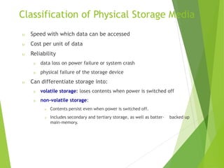
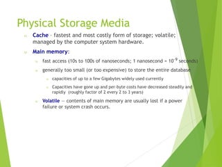
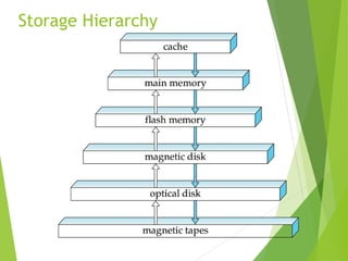


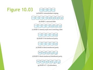
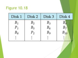
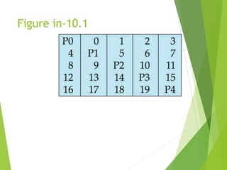

This document discusses physical storage media and file organization. It describes different types of storage media like magnetic disks, flash memory, and tape storage in terms of their speed, capacity, reliability and other characteristics. It also discusses the storage hierarchy from fastest volatile cache/memory to slower non-volatile secondary storage like disks to slowest tertiary storage like tapes. The document further explains techniques like RAID and file organization to optimize storage access and reliability in the presence of disk failures.