This document contains information about magnetic disk storage systems and RAID levels. It includes:
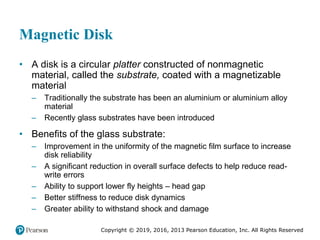
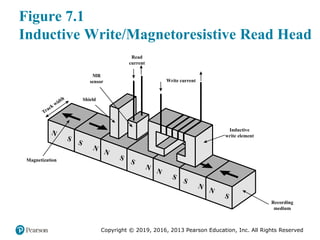
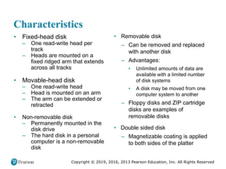
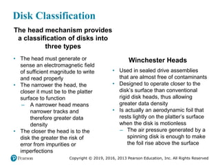
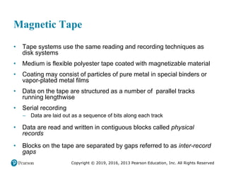
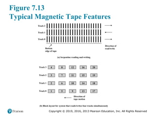
- Descriptions of magnetic disks, including their construction, read/write mechanisms, and data layout on disks.
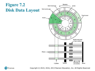
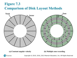
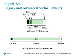
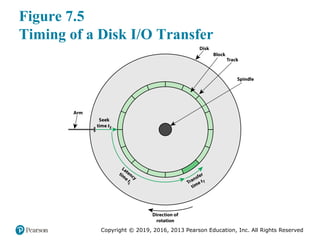
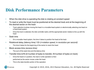
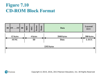
- Illustrations and explanations of disk formatting, sector formats, performance parameters like seek time and rotational latency.
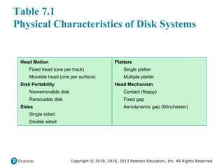
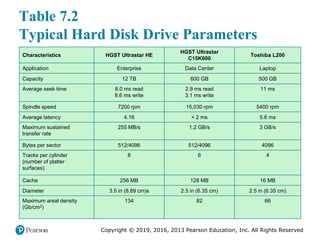
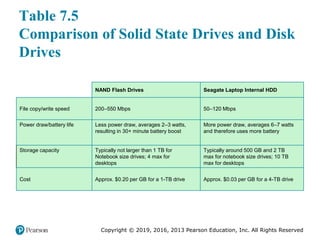
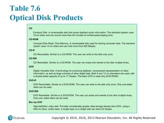
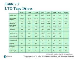
- Tables with examples of physical disk characteristics and specifications for different types of hard drives.
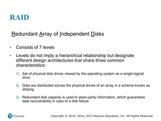
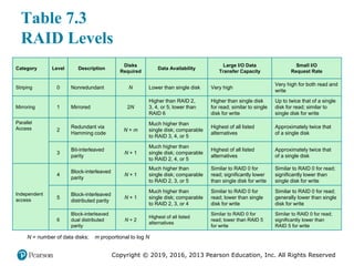
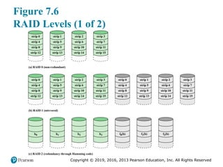
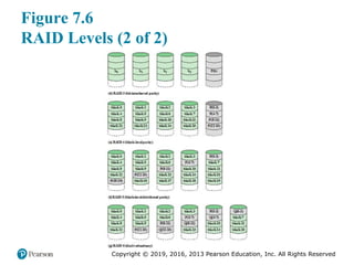
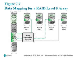
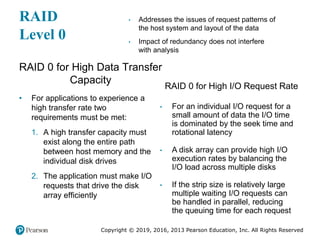
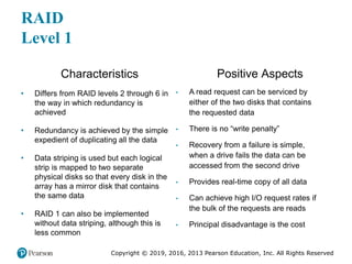
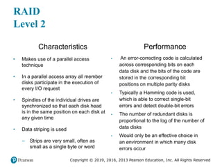
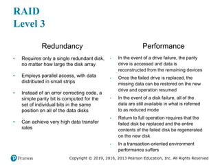
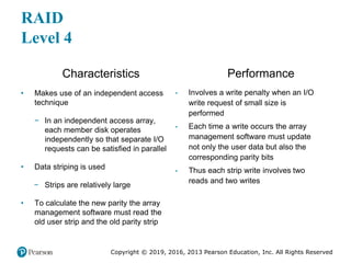
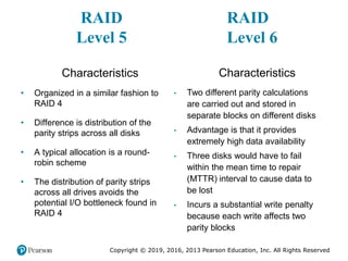
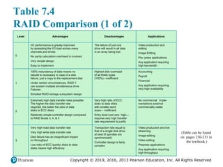
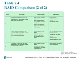
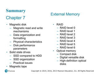
- An overview of RAID levels 0-6, their redundancy methods, required disks, data availability, performance for large and small I/O, and storage capacity.