Downloaded 1,709 times


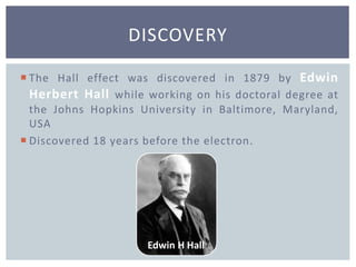
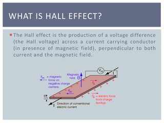
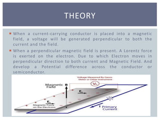
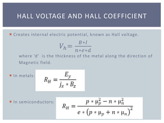
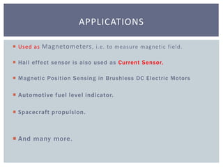
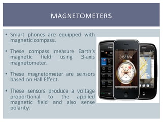
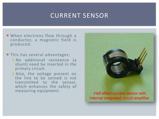
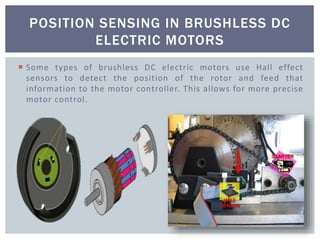
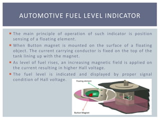


The document discusses the Hall effect and its applications. It was discovered in 1879 by Edwin Hall while working on his doctorate. The Hall effect produces a voltage difference known as the Hall voltage across a current-carrying conductor placed in a magnetic field that is perpendicular to both the current and the field. It is used in applications such as magnetometers in smartphones, current sensors, position sensing in brushless DC motors, and automotive fuel level indicators.