Downloaded 584 times

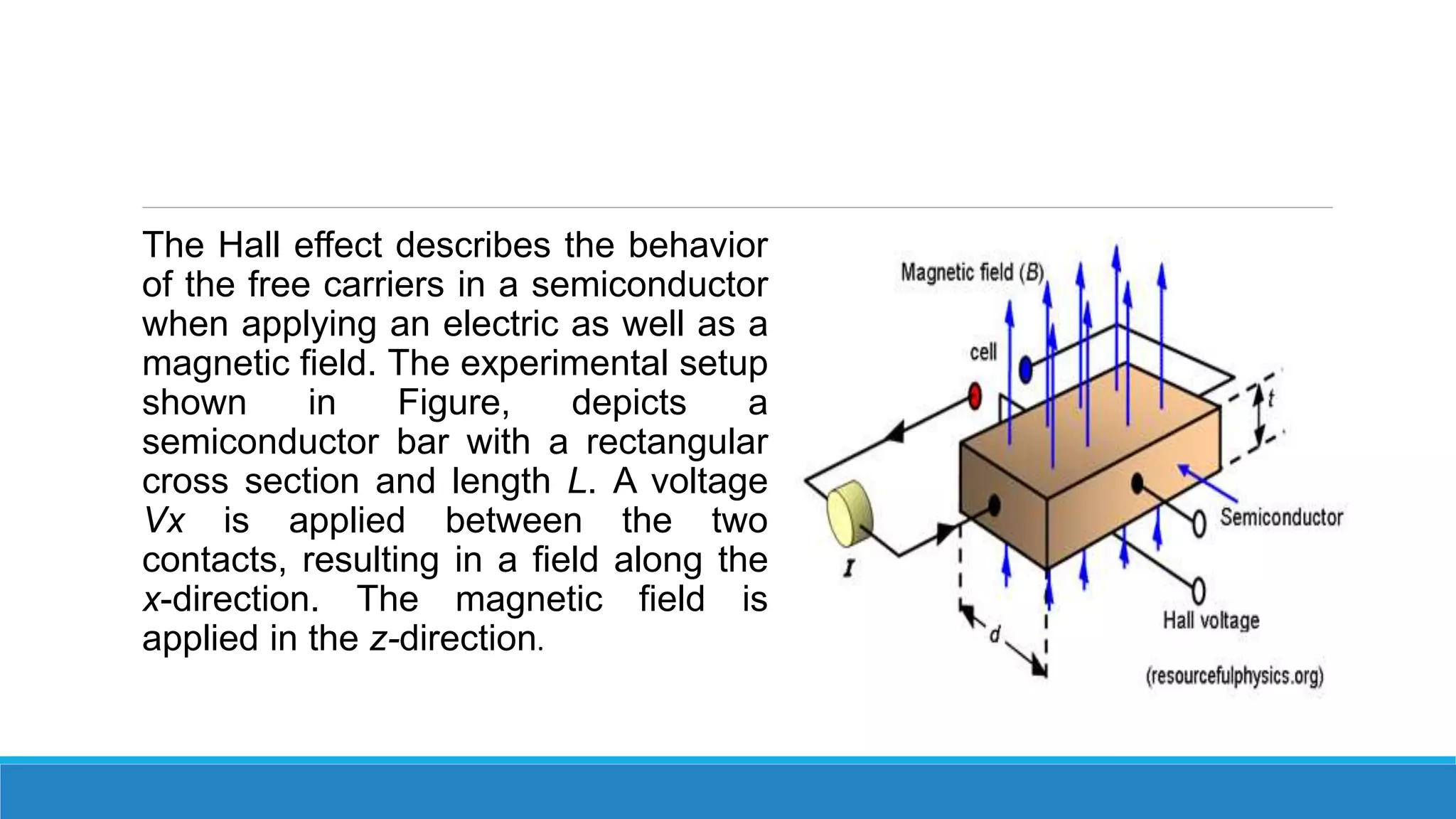
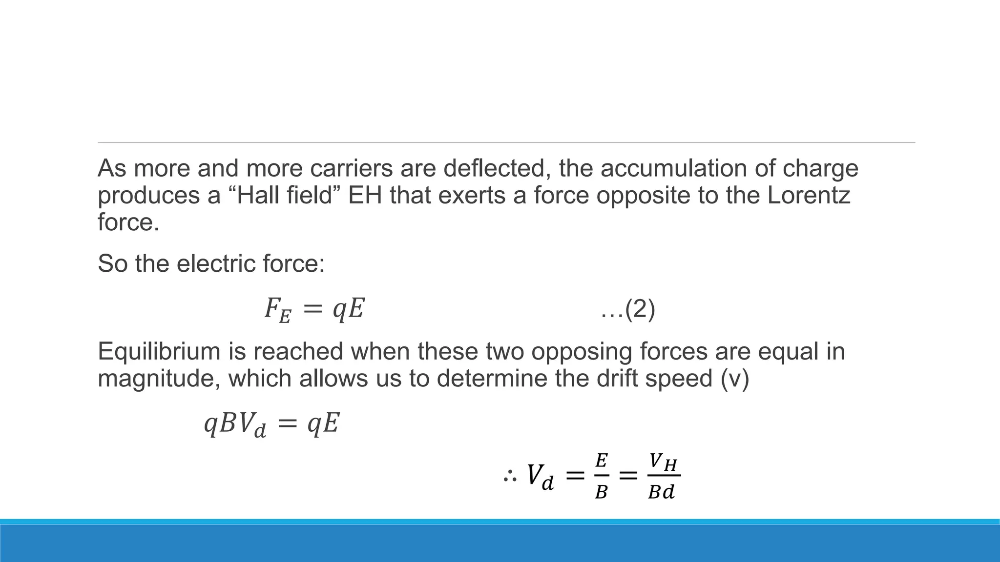
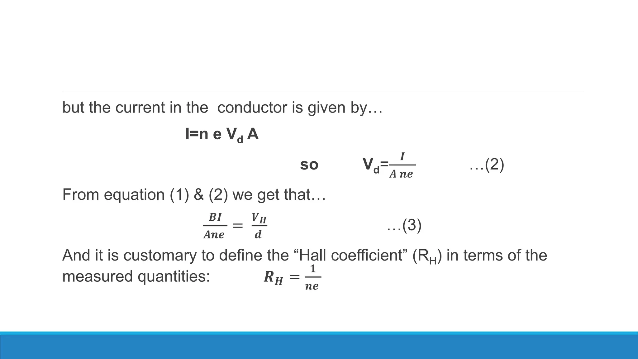
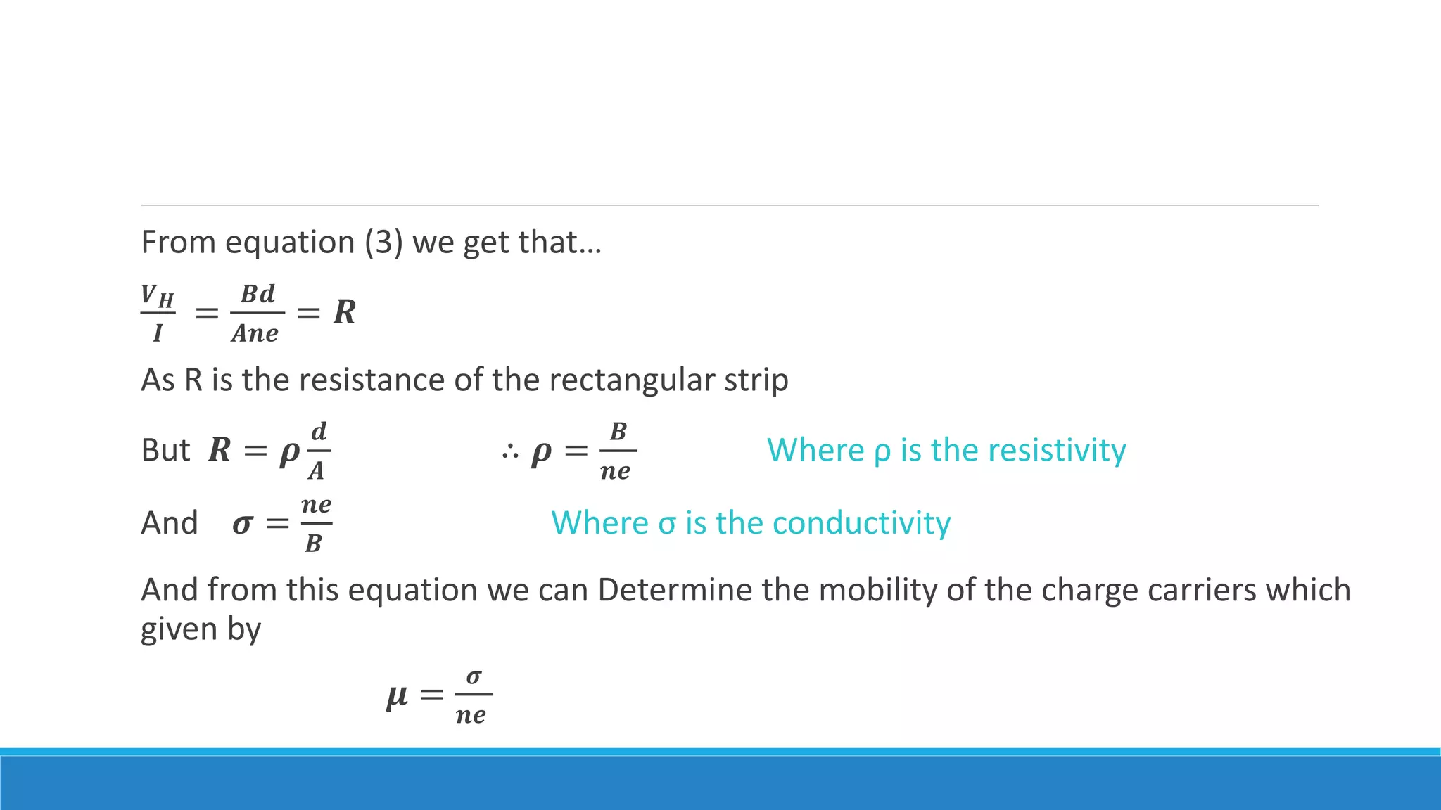
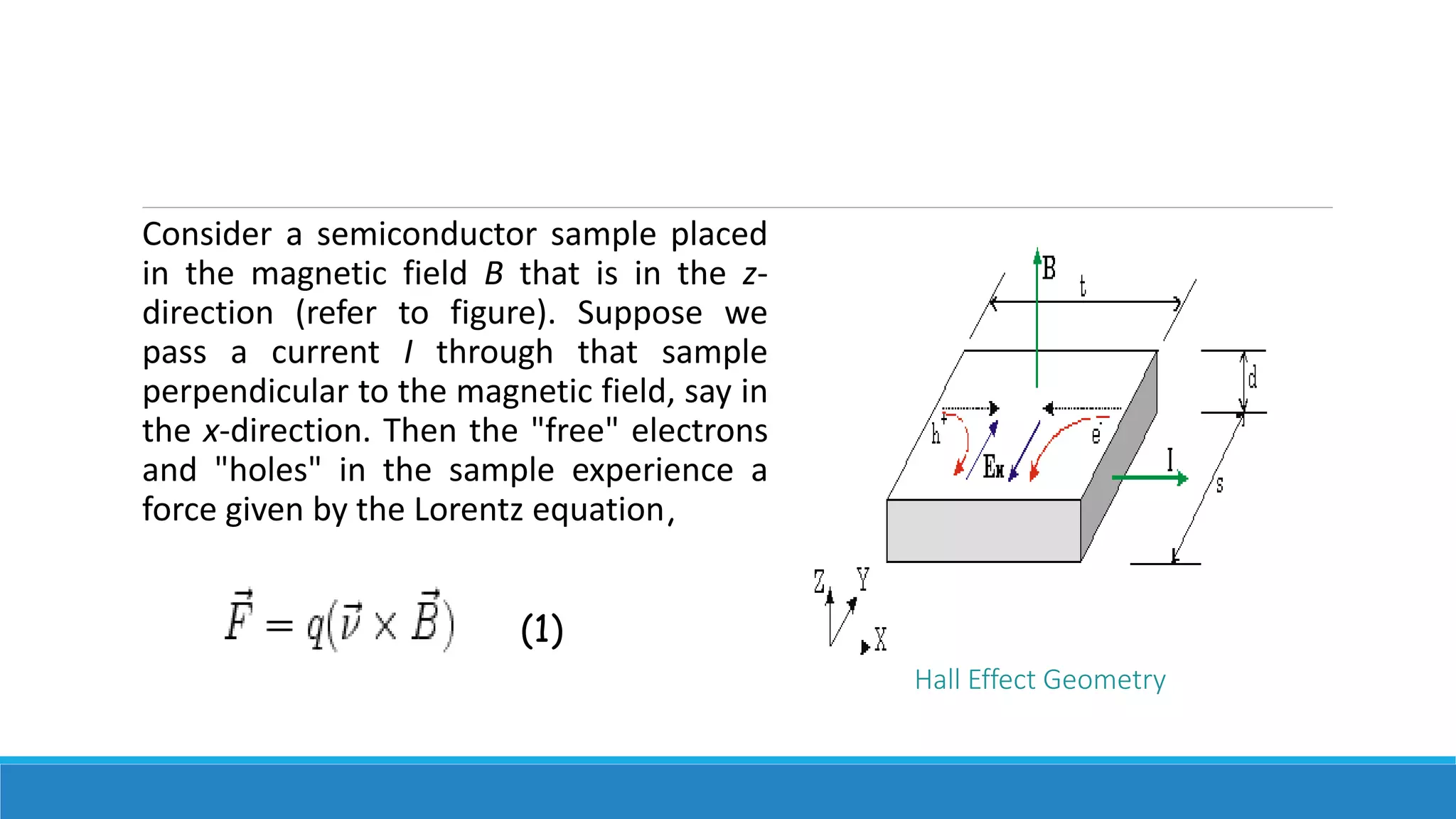
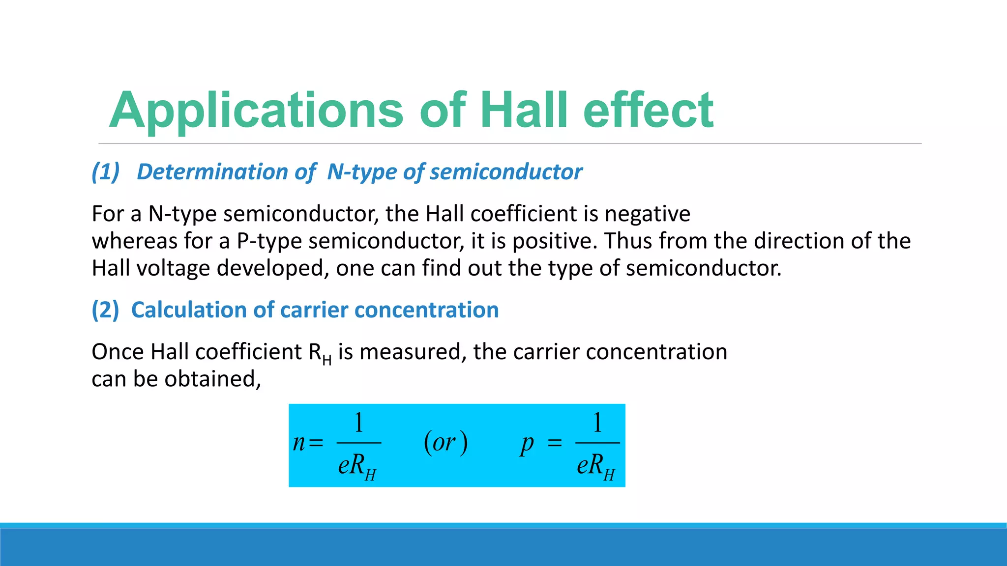
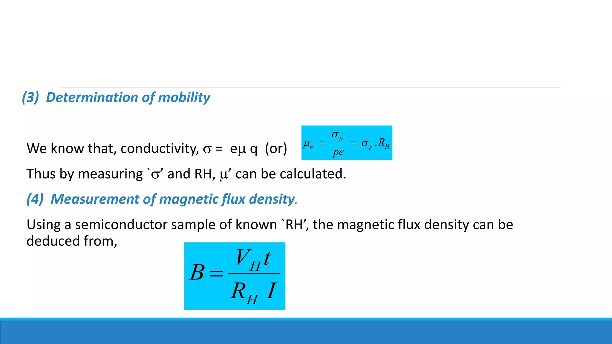

The Hall effect describes the behavior of charge carriers in a semiconductor when an electric and magnetic field are applied. When a current is passed through a semiconductor sample placed in a magnetic field perpendicular to the current, the Lorentz force causes charge carriers to deflect to the sides of the sample. This builds up a Hall voltage that can be measured. The Hall effect can be used to determine the type of semiconductor, calculate carrier concentration and mobility, and measure magnetic flux density.