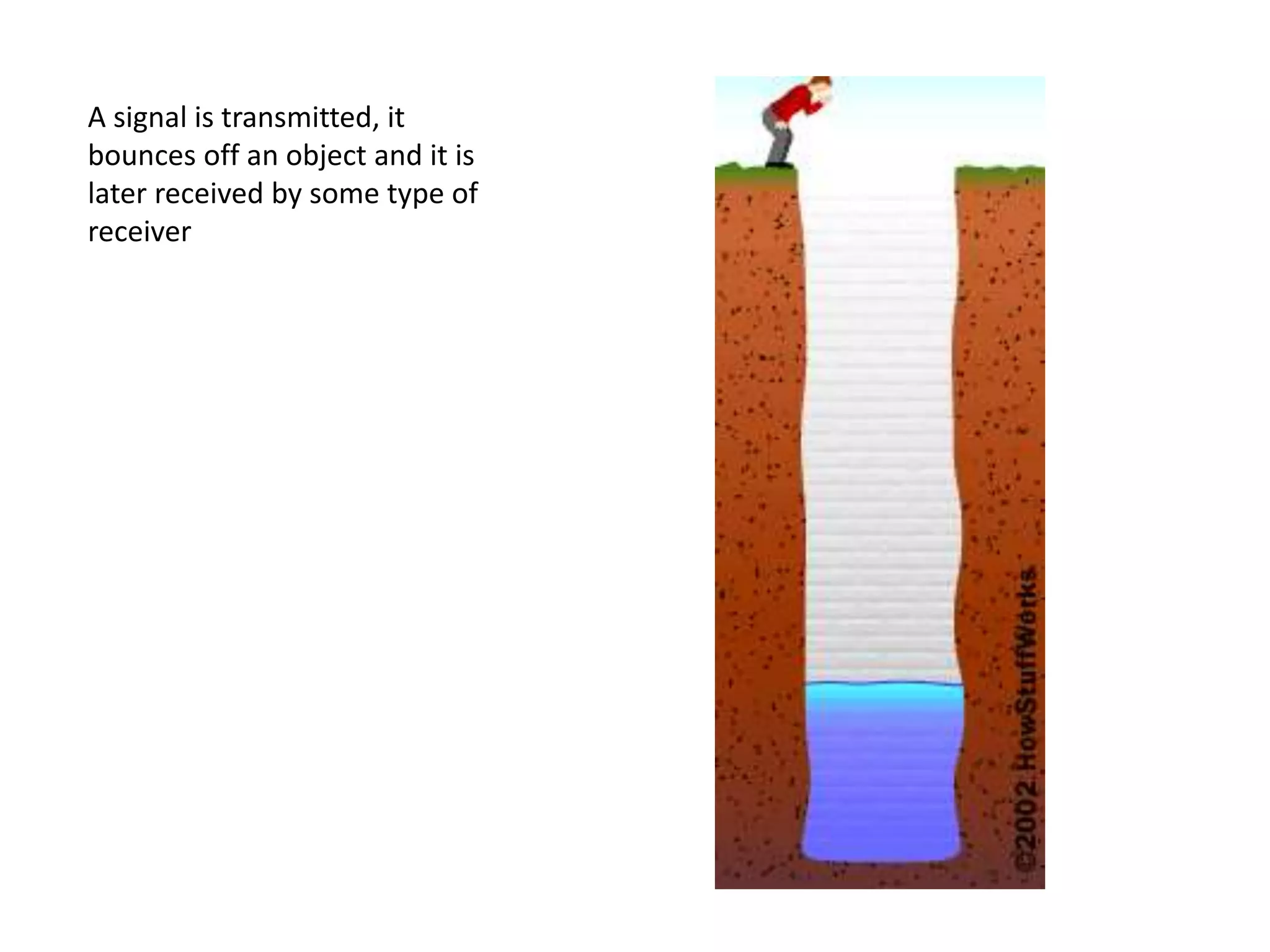
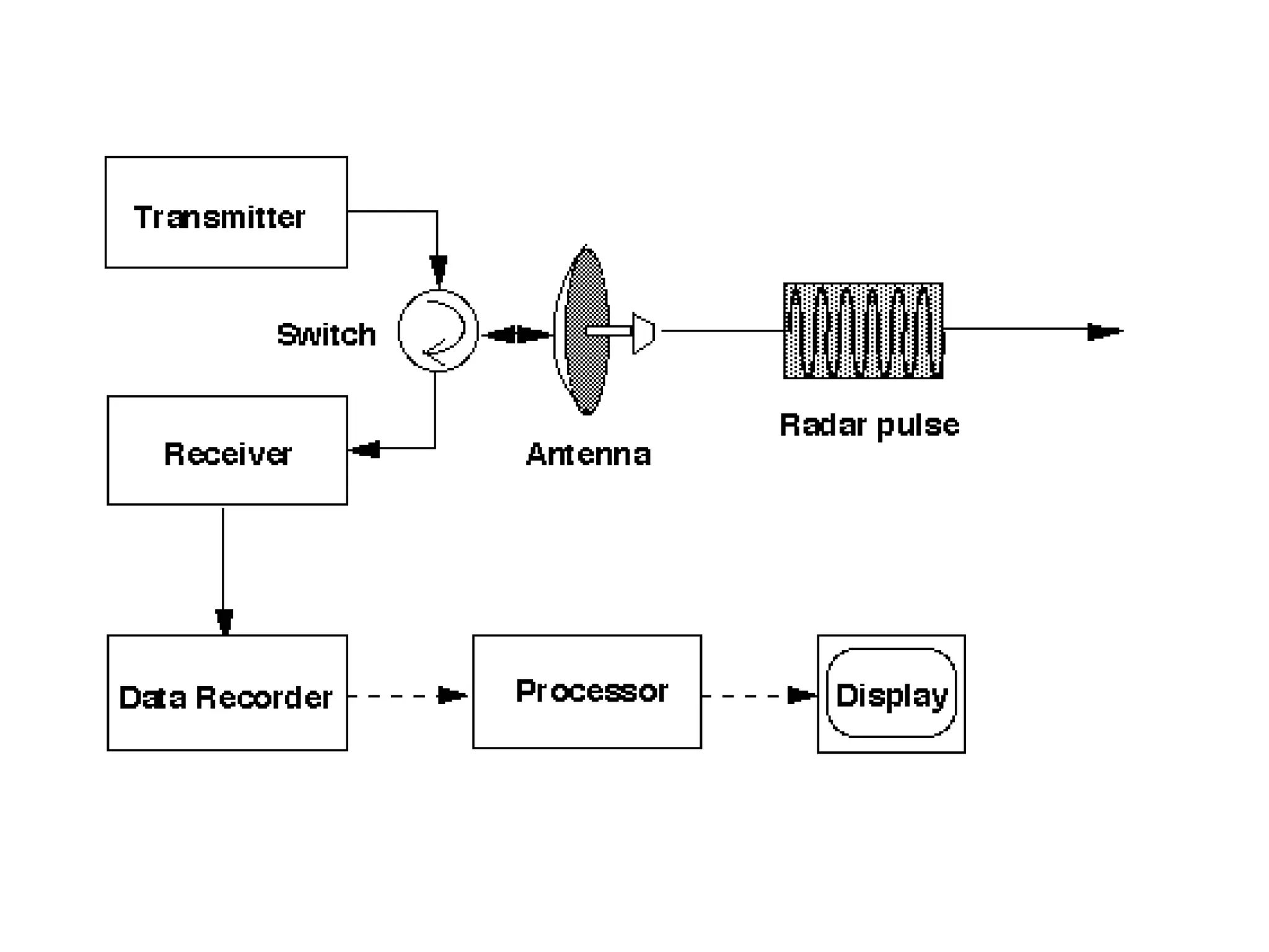
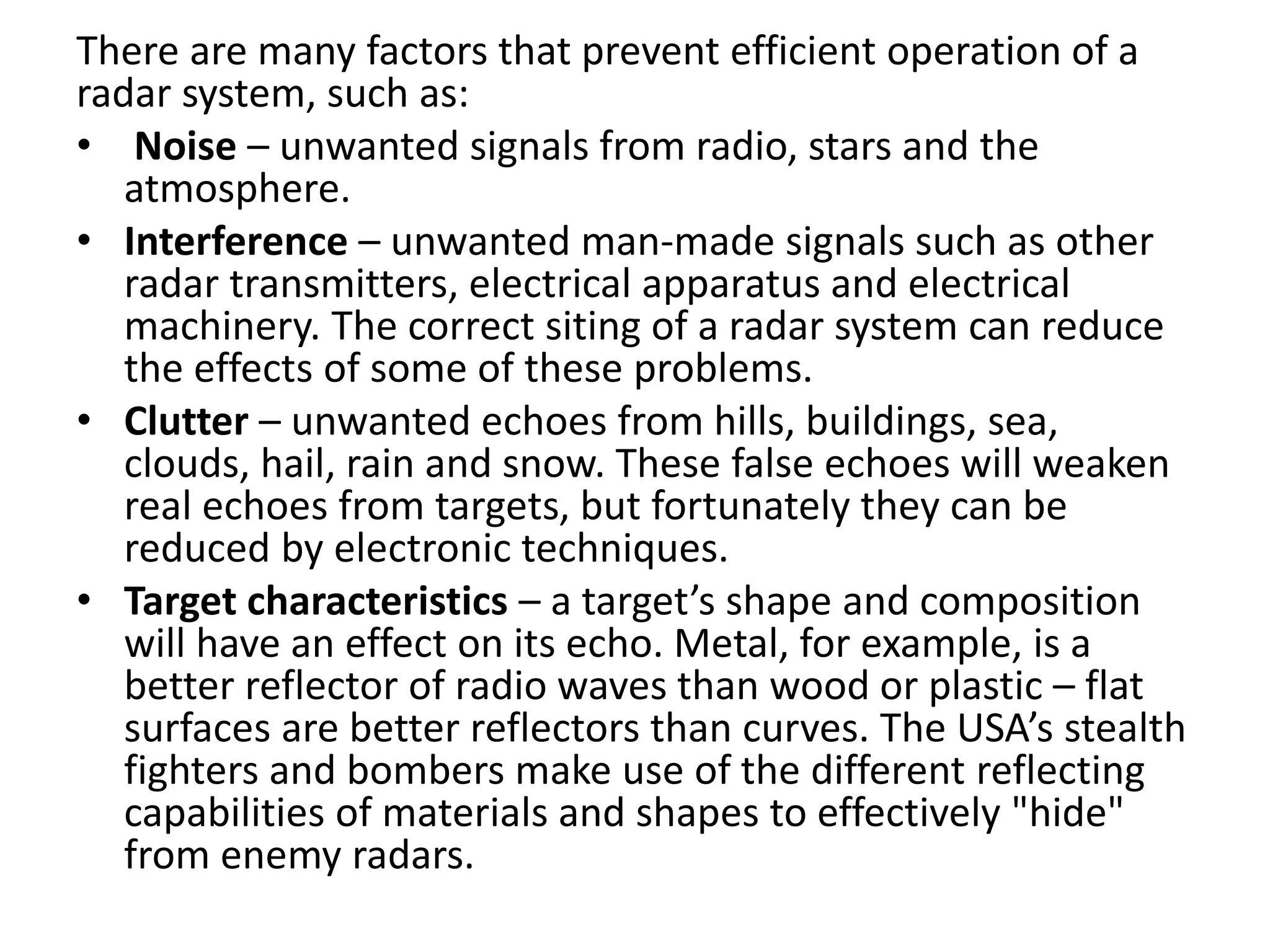
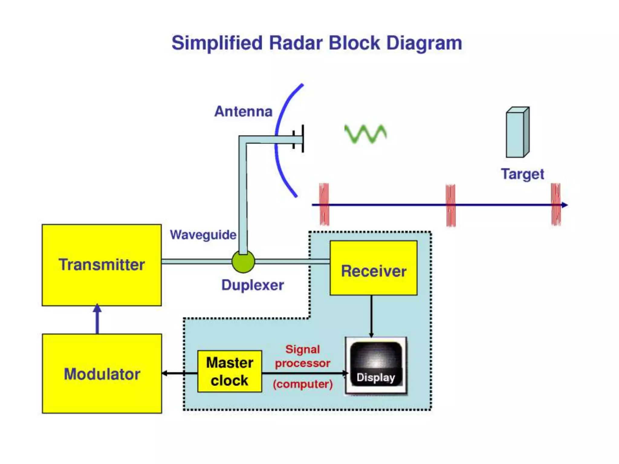
2. • RADAR
• RAdio Detection And Ranging.
• As World War II approached, scientists and the
military were keen to find a method of
detecting aircraft outside the normal range of
eyes and ears. They found one, and at first
called it Radio Detection Finding (RDF),
followed by RADAR.
3. • Radar works by firing powerful radio waves
towards the target, and collecting the
reflected energy.
• The radar operators can then find the position
of the target in terms of its range, intensity
and position.
4. A signal is transmitted, it
bounces off an object and it is
later received by some type of
receiver
5. • Radio waves and microwaves are two types of
electromagnetic waves. Electromagnetic waves.
• A basic radar system is spilt up into a transmitter,
switch, antenna, receiver, data recorder,
processor and some sort of output display.
• Everything starts with the transmitter as it
transmits a high power pulse to a switch which
then directs the pulse to be transmitted out an
antenna.
• Just after the antenna is finished transmitting the
pulse, the switch switches control to the receiver
which allows the antenna to receive echoed
signals.
6. • Once the signals are received the switch then
transfers control back to the transmitter to
transmit another signal.
• The switch may toggle control between the
transmitter and the receiver as much as 1000
times per second.
• Any received signals from the receiver are
then sent to a data recorder for storage on a
disk or tape.
• Later the data must be processed to be
interpreted into something useful which
would go on a display.
7.
8. • There are basically two types of Radar –
Primary and secondary.
• Both work on the same principle, however the
purpose is different.
9. Primary Radar
• A Primary Radar transmits high-frequency
signals which are reflected at targets.
• The arisen echoes are received and evaluated.
This means, unlike secondary radar, no reply is
required from the target.
10. Primary radar systems may be found in ground,
air, ship or space platforms and are used in roles
such as:
• Surveillance (including weather)
• Early warning
• Navigation
• Ground mapping (from space or aircraft)
• Guidance control
• Target detection and tracking
• Terrain following/avoidance
• Collision avoidance and altitude measurement
• Air Traffic Control
11. • Radars operate their high-powered radio
waves in 2 different modes: pulse-modulated
(pulsed) and continuous wave (CW).
• Most radars operate in the Ultra High
Frequency (UHF) or Super High Frequency
(SHF) bands. The Frequency of operation will
depend on the function the radar is to
perform,
12. • A pulse radar is a radar device that emits short
and powerful pulses and in the silent period
receives the echo signals.
• In contrast to the continuous wave radar the
transmitter is turned off before the
measurement is finished.
• This method is characterized by a radar pulse
modulation with very short transmission
pulses
13. • The speed of radio waves in free space, as we
know is 3 x 10⁸ ms-1 (186,000 miles per
second).
• So if we measure the elapsed time between
the transmission of the pulse and its reception
back at the radar, we can use the formula:
• Distance = Speed x Time
14. • The pulses from a radar are transmitted at a rate
which determines the range of the radar, called
the pulse repetition frequency or PRF.
• In practice the PRF might range from 250pps for
long-range radars to 2000pps for short-range
radars.
• For long-range radar, to get a satisfactory return
from a pulse, a massive one million watts
(megawatt) of radio frequency (RF) power is
required.
• This high power is used only during the brief
transmission of the pulse.
• The transmitter is then allowed to rest until the
next pulse and the receiver meanwhile is listening
for an echo.
15.
16. • Continuous Wave Radar transmit a high-
frequency signal continuously.
• The echo signal is received and processed.
• The receiver need not to be mounted at the same
place as the transmitter.
• Every firm civil radio transmitter can work as a
radar transmitter at the same time, if a remote
receiver compares the propagation times of the
direct signal with the reflected one.
• Tests are known that the correct location of an
airplane can be calculated from the evaluation of
the signals by three different television stations.
17. • Continuous Wave radar sets transmit a high-
frequency signal continuously.
• The echo signal is received and processed
permanently.
• One has to resolve two problems with this
principle:
• Prevent a direct connection of the transmitted
energy into the receiver (feedback
connection),
• Assign the received echoes to a time system to
be able to do run time measurements.
18. • A direct connection of the transmitted energy
into the receiver can be prevented by:
• Spatial separation of the transmitting antenna
and the receiving antenna, e.g. the aim is
illuminated by a strong transmitter and the
receiver is located in the missile flying
direction towards the aim;
• Frequency dependent separation by the
Doppler-frequency during the measurement
of speeds.
19. • There are two basic types of Continuous Wave
radar. These are called Continuous Wave
Doppler and frequency-modulated
Continuous Wave (FMCW).
20. • Consider the situation where a radar
equipment sends out a pulse of radio waves
and then "listens" for an echo.
• If the target is moving towards the Transmitter
the reflected waves become bunched up (i.e.
they acquire a higher frequency), due to the
target’s velocity.
• If the target is moving away, the waves are
spread out and their frequency drops slightly.
21. • Of course, a target rarely approaches the radar installation head-
on and in the diagram below, the target’s track (AC) is at an angle
to its bearing from the radar (AB).
• The velocity in direction AB is less than the true target speed in
direction AC.
• However, by comparing changes in Doppler shift at the radar
receiver over a short period, the target’s velocity can be
calculated.
22. • In the case of frequency-modulated
Continuous Wave , the transmitters signal is
made to vary in frequency in a controlled
cyclic manner with respect to time, over a
fixed band.
• By measuring the frequency of the returning
echo it is possible to calculate the time
interval elapsed since that frequency was
transmitted, and thus the target’s range.
23. Secondary Radar
• Radar was born in the due to the pressure of
war.
• The need to detect “hostile” aircraft led to a
vast investment in intellect and money to
develop RADAR.
• Classical Radar (now called Primary Radar) by
definition is a non co-operative technology,
that is it needs no co-operation from the
“Target” being detected.
• Why do we need a different system then?
24. • It is vital to know the identity of an aircraft
displayed on an air traffic controller’s screen,
particularly in a military situation.
• A method of identifying aircraft was first used
in the second World War and called
Identification Friend or Foe (IFF).
• It is still in use today
25. • As well as seeing “hostile” aircraft it soon became
apparent that Radar was a good tool to see “friendly”
aircraft and hence control and direct them.
• If the “friendly” aircraft is fitted with a transponder
(transmitting responder), then it sends a strong signal
back as an “echo”.
• An active also encoded response signal which is
returned to the radar set then is generated in the
transponder.
• This proved very useful for the military in seeing their
own aircraft clearly.
• In this response can be contained much more
information, as a primary radar unit is able to acquire
(E.g. an Altitude, an identification code or also any
technical problems on board such as a radio contact
loss ...).
26. • Secondary Radar relies on a piece of equipment aboard
the aircraft known as a 'transponder'.
• The IFF equipment is specifically for military use, but a
civilian version does exist, called Secondary
Surveillance Radar (SSR).
• Both systems are compatible with the ground based
interrogators which use a transmission frequency of
1030 MHz, while aircraft transponders use 1090 MHz.
• The transponder is a radio receiver and transmitter
operating on the radar frequency.
• The target aircraft's transponder responds to
interrogation by the ground station by transmitting a
coded reply signal.
27. The great advantages of Secondary Surveillance
Radar are:
• firstly, because the reply signal is transmitted
from the aircraft it is much stronger when
received at the ground station, therefore giving
the possibility of much greater range and
reducing the problems of signal attenuation;
• similarly, the transmitting power required of the
ground station for a given range is much reduced,
thus providing considerable economy;
• and thirdly, because the signals in each direction
are electronically coded the possibility is offered
to transmit additional information between the
two stations.
28. • The IFF/SSR systems have been developed so that
specific information can be obtained from an aircraft.
• The aircraft is interrogated on 1030 MHz using coded
pulses or modes.
• Similarly, the aircraft will respond on 1090 MHz using a
standard system of codes.
There are 3 modes in use and they are:
• Mode 1 Military Aircraft Identify
• Mode 2 Military Mission Identify
• Mode 3
A - Common Military/Civilian Aircraft Identify
B - Civil Identify
C - Height Encoded Data
29. • IFF/SSR system provide ATC authorities with a
wealth of information about particular aircraft
– far exceeding the amount of information
gained by simply using a primary radar.
• The types of information available are:
• Aircraft height (direct from aircraft’s altimeter)
• Direction
• Speed
• Type of aircraft
30. • The aircraft can also send emergency
information such as:
• Loss of radio communications (code 7600)
• Hijack (code 7500)
• SOS (code 7700)
31. The main advantages of IFF/SSR over primary
radar are:
• No clutter problems (i.e. unwanted returns
from rain clouds and mountains) since
transmitter and receiver operate on different
frequencies.
• Increased range with less transmitted power,
as the radio waves only have to travel one
way.
• More information from each target.
• Ability to use wide bandwidth receivers.
32. • Focusing radio waves into a beam requires a
much more complicated aerial system than a
simple straight wire.
• In order to produce a beam of radiation we
need to radiate from a shaped area, and not a
single wire.
• In theory, this means that for long
wavelengths great areas of aerial would be
needed.
• To overcome this problem, reflectors are used
on the aerial to reflect the radio waves in one
direction.
33. • The situation is very similar to the reflector in a
torch or headlight focusing the light into a narrow
beam.
• To detect accurate bearings of aircraft the aerial
is rotated through 360°, sweeping a narrow beam
of radiation in a complete circle (called scanning).
• All reflections can now be plotted around a circle
– with the aerial at the centre.
• To obtain vertical information about the aircraft
the aerial is moved up and down through 90° – in
a type of nodding movement.
• From the reflections received, accurate height
and range information can be measured.
34.
35. • Whenever a single antenna is used for both
transmitting and receiving, as in a radar system,
an electronic switch must be used!
• Switching systems of this type are called
duplexers.
• Switching the antenna between the transmit and
receive modes presents one problem; ensuring
that maximum use is made of the available
energy is another.
• The simplest solution is to use a switch to transfer
the antenna connection from the receiver to the
transmitter during the transmitted pulse and
back to the receiver during the echo pulse.
• No practical mechanical switches are available
that can open and close in a few microseconds.
Therefore, electronic switches must be used.
36.
37. • Transmitter. The transmitter creates the radio
wave to be sent and modulates it to form the
pulse train.
• Receiver. The receiver is sensitive to the
range of frequencies being transmitted and
provides amplification of the returned signal.
• Power Supply. The power supply provides the
electrical power for all the components.
• Synchronizer. The synchronizer coordinates
the timing for range determination.
• Display. The display unit may take a variety of
forms but in general is designed to present the
received information to an operator.
38. • Duplexer. This is a switch which alternately
connects the transmitter or receiver to the
antenna. Its purpose is to protect the receiver
from the high power output of the
transmitter.
• During the transmission of an outgoing pulse,
the duplexer will be aligned to the transmitter
for the duration of the pulse.
• After the pulse has been sent, the duplexer
will align the antenna to the receiver.
• When the next pulse is sent, the duplexer will
shift back to the transmitter
39. • Obtaining a target is only part of the detecting
process. The operator needs to "see" the
target in visual form.
• For this we use a cathode ray tube (CRT)
which works on a similar principle to a
television screen.
• As the time interval between pulses is short
the screen can be calibrated in miles to match
the range of the pulse
40. • All CRT's have three main elements: an electron gun, a
deflection system, and a screen. The electron gun
provides an electron beam, which is a highly
concentrated stream of electrons.
• The deflection system positions the electron beam on
the screen, and the screen displays a small spot of light
at the point where the electron beam strikes it.
• There are two possibilities for the deflection of the
electron beam:
• the electrostatic controlled deflection and focusing,
and
• the electromagnetic controlled deflection and focusing
of the electron beam.
41.
42. There are many factors that prevent efficient operation of a
radar system, such as:
• Noise – unwanted signals from radio, stars and the
atmosphere.
• Interference – unwanted man-made signals such as other
radar transmitters, electrical apparatus and electrical
machinery. The correct siting of a radar system can reduce
the effects of some of these problems.
• Clutter – unwanted echoes from hills, buildings, sea,
clouds, hail, rain and snow. These false echoes will weaken
real echoes from targets, but fortunately they can be
reduced by electronic techniques.
• Target characteristics – a target’s shape and composition
will have an effect on its echo. Metal, for example, is a
better reflector of radio waves than wood or plastic – flat
surfaces are better reflectors than curves. The USA’s stealth
fighters and bombers make use of the different reflecting
capabilities of materials and shapes to effectively "hide"
from enemy radars.
43.
44. What does RADAR stand for?
• Radar Detection and Ranging
• Radiation Aircraft Ranging
• Radio Detection and Ranging
• Ranging and Direction Radio
• Radio Detection and Ranging
45. How many modes are there in IFF/SSR?
• 4
• 1
• 2
• 3
• 3
46. What does SSR stand for?
• Secondary Surveillance Radar
• Service Surveillance Radio
• Single Side Radio
• Second Sense Radar
• Secondary Surveillance Radar
47. What does CRT stand for?
• Cathode Radio Tube
• Cathode Ray Tube
• Cathode Radiation Test
• Capacitor Resistor Transistor
• Cathode Ray Tube