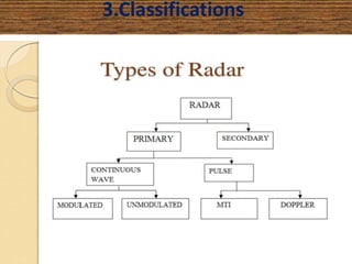
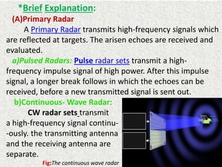
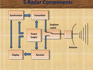
This document presents a detailed overview of radar technology, including its principles, classifications, components, and applications. It covers the basic functioning of radar systems, the historical development of radar, and important terminology associated with radar operation. Additionally, it lists key applications such as weather forecasting, law enforcement, and air traffic control.

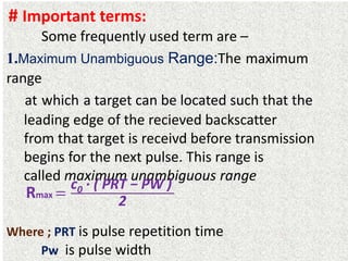
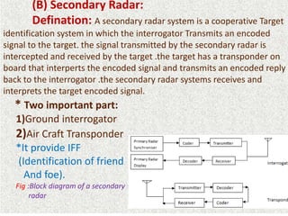
![# The Radar equation:
(Argumentation/Derivation)
Radar range equation represents the physical dependences of
the transmit power, one can assess the performance of the radar set
with the radar equation (or the radar range equation).
Non directional Power Density (su) :
Su =
Ps
4 · π · R1
2
Directional Power Density (sg) :
Sg = Su · G
The reflected power Pr :
Pr =
Ps· G · σ
4 · π · R1
2 [W/m2]
The received power PE :](https://image.slidesharecdn.com/radarsystem-160725203002/85/Radar-system-12-320.jpg)
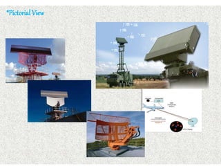
![PE =
Ps · G2· σ · λ2
(4 · π)3 · R4
The Antenna Gain (G):
G =
4 · π· A · Ka
λ2
The radar range equation:
R=
4 Ps · G2· σ · λ2
(4 · π)3.PE
Where: PS = transmitted power [W
σ = radar cross section [m2]
R1 = range, distance antenna - aim [m]
R2 = range aim - antenna [m]
Aw =Effective apparture antenna [𝑚2
]
=A · Ka](https://image.slidesharecdn.com/radarsystem-160725203002/85/Radar-system-13-320.jpg)