Downloaded 1,392 times


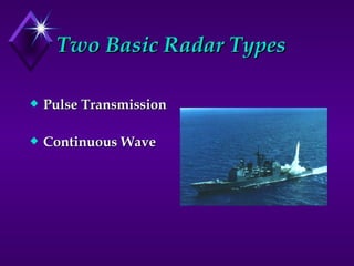


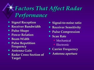


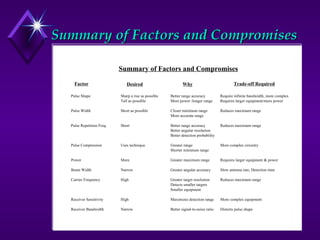


The document discusses different types of radar systems and their components and principles of operation. It covers topics like pulse radar vs continuous wave radar, components of each type of system like transmitter, receiver, antennas, and how factors like pulse width, repetition frequency and power affect radar performance and capabilities. It also discusses modulation techniques, antenna beam formation, and different types of radar displays.