Downloaded 773 times

![Radar Range Equation
Rmax = [Pt .G.б.Ae / (4П)2Smin]1/4
G = 4ПAe / λ2
Ae = G.λ2 / 4П
Where Smin = Minimum power received
Pt = Power transmitted
G = antenna gain
б = radar cross section of target
Ae= effective area
Rmax = Maximum Radar Range](https://image.slidesharecdn.com/introduction-140926041430-phpapp01/85/Study-of-Radar-System-PPT-4-320.jpg)
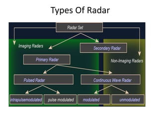


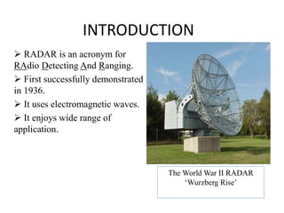
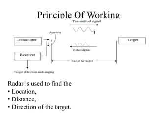
This document summarizes Atul Sharma's training report on studying radar systems during an internship from June 16th to July 26th 2014. It introduces radar technology, explaining that radar uses radio waves to detect objects and determine their location, distance and direction. It then describes the basic principles of how radar works, including the radar range equation. It also outlines the main components of a radar system, such as the antenna, transmitter, receiver and display, and different types of radars like primary and secondary radar. Finally, it provides examples of specific radar sets used in India.


