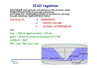
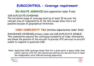
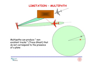
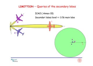
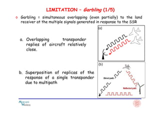
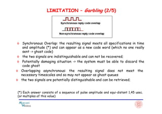
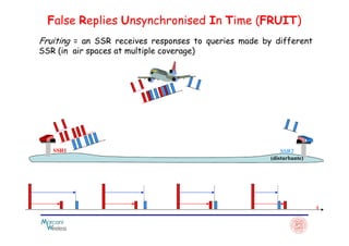
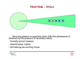
Secondary Surveillance Radar - SSR
◊ Radar Primary (Primary Surveillance Radar - PSR) radiates an
EM wave and receives the echo reflected from any objects
detecting the presence, distance and azimuth, but not the
identity.
Introduction (1/2)
◊ Identification Friend or Foe (IFF) – first identification
system used by the Air Britain during World War II:
airplanes equipped with IFF were able to respond with aairplanes equipped with IFF were able to respond with a
precise signal (radio) the question (radio) received from
a transmitter to the ground;
◊ Il Radar Secondario (Secondary Surveillance Radar – SSR)
IFF represents an evolution that meets the needs of
the Air Traffic Control(Air Traffic Control – ATC)
◊ The secondary radar (SSR) is co-
operative because it requires the
transponder on board the aircraft.
The secondary radar gives 3 coordinates of the plane:
Introduction (2/2)
◊ The secondary radar (SSR), with the exception of
barometric altitude, is independent because is the
ground unit that calculates the distance and azimuth of
the plane.
- distance from the sensor
- azimuth with respect to a reference direction
- quote obtained from a dedicated altimeter
generality
primary radar (PSR) plane is a passiv element
Reflects part of the electromagnetic energy that invests itself
Secondary radar (SSR) plane is as active element
answers to the solicitation raised by the radar
Principle (1/3)
◊ The secondary radar system is capable of detecting the presence of aircraft
that are equipped with a special unit (Transponder) to respond to the
solicitation that come from the ground.
◊ The unit of land (Query-RECEIVER) SSR periodically broadcasts (with time
interval = PRT - Pulse Repetition Time), the "coded questions" by means of a
rotating directional antenna;
◊ TRANSPONDER :The board receives the individual questions, after decoding
them, it will transmit single "responses coded" (sequences of pulses of
appropriate features).appropriate features).
◊ RESPONDER: The response obtained from the satellite allow to calculate
ground station azimuth and distance, using the same technique of a primary
radar, and decoding the pulses of the response can give also additional
information additional information.
TRANSPONDER
1030 MHz
Principle(2/3)
INTERROGATORE
RICEVITORE
1090 MHz
Receiver
Directional Antenna especially in the horizontal plane to obtaine
ottenere:
precisione
azimut resolution
interrogation frequency Fi = 1030 MHz (Up-Link)
TRANSPONDER
Principle (3/3)
quasi Omnidirectional antenna
answer frequency Fr = 1090 MHz (Down-Link)
SSR frequencies
- standardized by the ICAO
- allow you to use the same antenna to transmit and receive
- not interfere with the PSR
DISTANCE and azimuth calculated as the primary radar
IDENTIFICATION initial and continuing
AUTOMATIC TRANSMISSION of barometric altitude
PULSE SPECIAL IDENTIFICATION
Indication of: EMERGENCY
RADIO FAILURE
ILLEGAL INTERFERENCE
con:
flow = 200 nm (nautical mile) ~ 370 km
ICAO regulation
flow = 200 nm (nautical mile) ~ 370 km
quote = 30 km for elevation between 0,5° e 45°
AZIMUT = 360°
PRF = max 450 interr./sec
EUROCONTROL – Coverage requirement
EN-ROUTE AIRSPACE (min separation radar 5 nm)
SSR DUPLICATE COVERAGE:
The horizontal scope of coverage must be at least 30 nm over the
relevant area of ​​responsibility of the ACC except when this is not
possible because of geographical limitations.
HIGH COMPLEXITY TMA (minima separazione radar 3nm)
INSURANCE COVERAGE primary radar and SSR DUPLICATA SINGLE:INSURANCE COVERAGE primary radar and SSR DUPLICATA SINGLE:
This combination ensures the continuous availability of radar information
and allows the position of the aircraft to provide ATC services to aircraft
unable to respond to questions SSR.
Note: duplicated SSR coverage means that for a given point in space radar data
center used by ATC for the monitoring function are derived from at least
two independent units SSR and working separately.
LIMITATION – MULTIPATH
Multipaths can produce " non-
existent tracks " (Trace Ghost) that
do not correspond to the presence
of a plane
LIMITTION – Queries of the secondary lobes
AB
C
ICAO ( Annex 10)
Secondari lobes level <= 1/16 main lobe
C
A
C B
Queries
consist of 2 RF pulses (1030 MHz) of duration of 0,8 µµµµsec :
Mode 3/A
Identification and monitoring
0,8 µµµµs
8 µµµµs
P1 P3
1030 MHz
1030 MHz
Mode C
height of the aircraft
0,8 µµµµs
21 µµµµs
P1 P3
1030 MHz
SLS -Side Lobe Suppression
In the secondary radar transponder can be triggered by questions from
the detection of secondary lobes producing aircraft in the wrong locations.
The SLS technique allows the transponder to "recognize" if the query
comes from the main lobe (in this case the transponder responds) or lobes
(in this case the query is ignored).
The SLS technique is performed with the transmission of a control pulse
P2 (same duration and frequency of P1 and P3) sent 2 usec. after the
pulse P1.
The transponder performs the "recognition" of the origin of the questionThe transponder performs the "recognition" of the origin of the question
(from the main lobe or side lobes) by comparing the amplitudes of the
pulses received (P1, P2, P3).
Amplitude P1 of P3 ≥≥≥≥ 2,8 time that of P2 transponder
respond
Amplitude di P1 e P3 <<<< 2,8 time that of P2 il transponder do
not respond
2 µµµµs
SLS -Side Lobe Suppression
P3P1
Amplitude
of pulses
received
from the
transponder
TRANSPONDER
RESPOND
AREA OF
UNCERTAINTY
2,8 P2
0,8 µµµµs
P2
The amplitude of P1 must be > 2.8 times that of P2
The pulse P2 is not participating in the determination of
the mode
TRANSPONDER DO
NOT RESPOND
UNCERTAINTY
SLS -Side Lobe Suppression
The SLS technique can be performed with two different solutions:
- SLS auxiliary omnidirectional antenna
- SLS antenna "monopulse"
SLS WITH AUXILIARY OMNIDIRECTIONAL ANTENNA
In this realization P1 and P3 pulses are transmitted through
the directive antenna while the pulse P2 is transmitted
through the auxiliary omnidirectional antenna.
The omnidirectional antenna characteristics must be such that
through the auxiliary omnidirectional antenna.
The omnidirectional antenna characteristics must be such that
the signal in all directions, P2 must be larger than (P1 and P3)
transmitted from the largest lobe and considerably less than
that transmitted by the main lobe of the antenna directive.
SLS WITH AUXILIARY OMNIDIRECTIONAL
ANTENNA (1/2)
P1 P3
P2
AEREO A
TRANSPONDER RESPOND
P1 P3
P2
AEREO B
P1 P3
P2
AEREO C
TRANSPONDER DO NOT RESPOND
H
3°
The SLS carried out with the Auxiliary omnidirectional antenna does
not give a good response to high angles where it is difficult to keep
under control the radiation pattern of the two antennas (main and
auxiliary) to ensure the correct amplitude ratios between P1 and P2-
P3 .
SLS WITH AUXILIARY OMNIDIRECTIONAL
ANTENNA (2/2)
R
The sum and difference antenna SLS offers better performance.
◊ Garbling = simultaneous overlapping (even partially) to the land
receiver at the multiple signals generated in response to the SSR
LIMITATION – Garbling (1/5)
a. Overlapping transponder
replies of aircraft relatively
close.
(a)
b. Superposition of replicas of the
response of a single transponder
due to multipath
(b)
LIMITATION – Garbling (2/5)
◊ Synchronous Overlap: the resulting signal meets all specifications in time
and amplitude (*) and can appear as a new code word (which no one really
sent -> ghost code)
◊ the two signals are indistinguishable and can not be recovered;◊ the two signals are indistinguishable and can not be recovered;
◊ Potentially damaging situation -> the system must be able to discard the
code ghost
◊ Overlapping asynchronous: the resulting signal does not meet the
necessary timescales and so may not appear as ghost queues
◊ the two signals are potentially distinguishable and can be retrieved;
(*) Each answer consists of a sequence of pulse amplitude and equi-distant 1,45 usec.
(or multiples of this value)
LIMITATION – Garbling (3/5)
Overlapping transponder replies of aircraft relatively close.
EffeCT
Inability to distinguish both aircraft
Normally, information and code share will be lost
Possibility of "receive" ghost codes (phantom or ghost code)
In high-density airspace traffic aircraft in flight along the same airway can
produce "garbling" for long periods
PROTECTION
- Ignore the impulse responses with the presence of unexpected
- Store the received codes, when the planes were not so close as to
produce garble, and extract the correct codes from correlation
algorithms using garble;
- Separate the pulses from a transponder from the other through an
accurate measure of the duration and amplitude of individual pulses
and the time interval between one pulse and the other (The
LIMITATION – Garbling (4/5)
and the time interval between one pulse and the other (The
transponders are not all "equal" and the pulses belonging to a same
answer - the same transponder - they normally have similar amplitude
and duration)
convenzional SSR
respons
LIMITATION – Garbling (5/5)
Overlap of replicas of the
response of a single
transponder due to
multipath
◊ Very often the echo amplitude has a different (lower) than the
direct signal -> garbling can be detected and the code recovered by
means of algorithms of correlation;
◊ If the transponder is activated by a lobe, the echo can be detected
by the main lobe and then the amplitudes of the two signals can be
comparable -> potential "ghost code" FF30
Diapositiva 22
FF30 Si noti che in questo caso, ANCHE qualora il garbling venisse risolto, la stima di posizione sarebbe comunque errata perche' se il Transponder e'
attivato da un lobo secondario comunque la posizione verrebbe stimata lungo la direzione del lobo principale
Franco Fuschini; 26/05/2008
False Replies Unsynchronised In Time (FRUIT)
Fruiting = an SSR receives responses to queries made ​​by different
SSR (in air spaces at multiple coverage)
SSR1 SSR2
(disturbante)
t
FRUITING - Effect
- Receiving answers to questions other SSR (the phenomenon is
enhanced by the presence of secondary lobes)
- formally correct answers
- Asynchronous replies
- Introducing non existing traces
The probability of FRUIT increases with the number of
aircraft, the number of interrogations-receivers and the
number of questions -> can be limited by minimizing the
number of queries (without degrading the performance of
the radar);
Very often the "false replicas" are received by an SSR
"through" the lobes of the radiation pattern -> Side Lobe
FRUITING – Protection (1/2)
"through" the lobes of the radiation pattern -> Side Lobe
Suppression of reduces the number of FRUIT;
FRUITING – Protection (2/2)
The asynchronous replication can be "filtered" by controlling
the PRT receive:
- Depending on the PRT of SSR, the rotation speed and scale
of the antenna radiation lobe, each aircraft is subject to a
number nI of queries each time it is "pointing" the antenna of
the SSR (typically nI ~ 16);
- The transponder responds to all queries and therefore the
"repetition period of the answers" is the same period of the"repetition period of the answers" is the same period of the
interrogation signal (and therefore equal to PRT)
- SSR have different different PRTs -> "false replicas" can
be recognized because they are repeated with a period
different from that SSR receives the PRT
- Circuits Defruiting: store all the responses received, grouped
according to the period of repetition and eliminate all the answers
with a period of PRT ≠ by SSR
SSR + PSR
Responses(1/2)
• Series of pulses each lasting 0.45 usec
• Duration of response = 20.3 usec (the length is constant)
• Maximum number of pulses in response = 14
• 1 ° and 14 ° pulse (pulse-frame brackets pulses) are always present
• Interval between one pulse and the other = 1.45 sec or multiples
• The answer to Question A is the mode ID CODE
• The answer to questions is the Mode C FEE
• The response code is selected manually
• The answers to questions are Mode C automaticThe answers to questions are Mode C automatic
• Number and location of the pulses in the answer varies depending on:
- query mode (A or C)
- response code or selected value of the share
• Ability to pass a special impulse SPI (Special Position Identification)
• SPI transmitted 4.35 usec after the second frame pulse
• The transmission of the SPI is activated manually and is repeated for a
time between 15 and 30 seconds.
F1 C1 A1 C2 A2 C4 A4 B1 D1 B2 D2 B4 D4 F2 SPI
1° 2° 3° 4° 5° 6° 7° 8° 9° 10° 11° 12° 13° 14° 15°
1,45 µµµµs
1090 MHz
Responses(2/2)
1,45 µµµµs
20,3 µµµµs 4,35 µµµµs
24,65 µµµµs
CODE
SSR CODE 4-digit number expressed in octal number system
(can not use the digits 8 and 9)
Code (1/2)
Rules for the calculation of the code
Pulse A1, B1, C1, D1 associated value 1 if present in the response, 0 if absent
Pulse A2, B2, C2, D2 associated value 2 if present in the response, 0 if absent
Pulse A4, B4, C4, D4 4 if present value associated with the response, 0 if absent
1th digit identification code associated with the sum of the pulses A
2th digit identifier sum of the values ​​associated with the pulses B
3th digit identification code associated with the sum of the pulse C
4th digit of the sum of the identification code associated with the pulses D
ORDERING INFORMATION AVAILABLE = 4096 (from 0000 to 7777)
RESERVED CODES
7500 Hijack
7600 Radioavaria
7700 Emergency
0000 General Purpose (regional agreements)
2000 ATC received no instruction to operate the transponder
EXAMPLE:
F1 C1 A1 C2 A2 C4 A4 B1 D1 B2 D2 B4 D4 F2
1° 2° 3° 4° 5° 6° 7° 8° 9° 10° 11° 12° 13° 14°
F1 C1 A1 C2 A2 C4 A4 B1 D1 B2 D2 B4 D4 F2
1° 2° 3° 4° 5° 6° 7° 8° 9° 10° 11° 12° 13° 14°
4321
4567
I Codici (2/2)
1° 2° 3° 4° 5° 6° 7° 8° 9° 10° 11° 12° 13° 14°
F1 C1 A1 C2 A2 C4 A4 B1 D1 B2 D2 B4 D4 F2
1° 2° 3° 4° 5° 6° 7° 8° 9° 10° 11° 12° 13° 14°
F1 C1 A1 C2 A2 C4 A4 B1 D1 B2 D2 B4 D4 F2
1° 2° 3° 4° 5° 6° 7° 8° 9° 10° 11° 12° 13° 14°
2000
7700
SSR – height(1/2)
The information obtained from an altimeter altitude are "dedicated" and sent to
an analog-digital converter (encoder) that automatically selects the answer to
the altitude in increments / decrements of 100 feet in +126,750 -1,000 feet.
You need only 1278 different combinations (available 4096) of the pulse
response.
- Enabling the automatic transmission of information is carried by the pilot.
- The information transmitted is always referred to the share standard
pressure (1013.25 hPa).
- Share the information submitted have an uncertainty of ± 50 ft (eg in the
range +9,950 +10,050 ft and the unit value is always sent in response to +10,000range +9,950 +10,050 ft and the unit value is always sent in response to +10,000
ft.)
Share information to the controller are presented (as shown in the label):
immediately after decoding the transition level (TL) up
relate them to the correct pressure at sea level (QNH) in that area below the
TL.
SSR – height(2/2)
The method of encoding, specified in Annex 10 of ICAO, are such as to avoid
ambiguities and errors.
If the transponder does not have the information available pressure-part answer to
a question Mode C transmitting only the pulses parentheses.
F1 C1 A1 C2 A2 C4 A4 B1 D1 B2 D2 B4 D4 F2
1° 2° 3° 4° 5° 6° 7° 8° 9° 10° 11° 12° 13° 14°
Height data not availble
The information of altitude are always referred to the standard pressure (the
pilot can not change the altimeter setting encoder that sends data to the
transponder).
If the pilot manually adjusts the altimeter on board the local QNH, share
information verbally transmitted to ATC and the data transmitted from the
transponder altitude are different.
Only if the user (ATC) "corrects" the information received, relating them to the
local QNH, the two data (verbal transmission of the pilot and altitude on the
label) coincide.
SSR –height encoding
R A N G E
P U L S E P O S I T I O N S
( 0 o r 1 in a p u ls e p o s itio n s d e n o te s a b s e n c e o r p r e s e n c e o f a p u ls e ,
r e s p e c tiv e ly )
I N C R E M E N T S
( F e e t s )
D 2 D 4 A 1 A 2 A 4 B 1 B 2 B 4 C 1 C 2 C 4
9 7 5 0 to 9 8 5 0
9 8 5 0 to 9 9 5 0
0 0 0 1 1 1 0 1
0 0 0 1 1 1 0 1
0 0 1
0 1 1
For the transmission of data pulses shall be used A and B, C pulse. C is always
present but at least one C1 and C4 never appear together in the same response,
the pulse D1 is never used.
9 9 5 0 to 1 0 0 5 0
1 0 0 5 0 to 1 0 1 5 0
1 0 1 5 0 to 1 0 2 5 0
0 0 0 1 1 1 0 1
0 0 0 1 1 1 0 1
0 0 0 1 1 1 0 1
0 1 0
1 1 0
1 0 0
1 0 2 5 0 to 1 0 3 5 0
1 0 3 5 0 to 1 0 4 5 0
1 0 4 5 0 to 1 0 5 5 0
1 0 5 5 0 to 1 0 6 5 0
1 0 6 5 0 to 1 0 7 5 0
0 0 0 1 1 1 0 0
0 0 0 1 1 1 0 0
0 0 0 1 1 1 0 0
0 0 0 1 1 1 0 0
0 0 0 1 1 1 0 0
1 0 0
1 1 0
0 1 0
0 1 1
0 0 1
The height information provided from SSR is encoded in increments of
100ft and have an uncertainty of ± 50 ft, while the modern aircraft
altimeters generally have greater accuracy and resolution.
The encoding in increments of 100 ft is sufficiently accurate to be
displayed in the label associated to the plane and presented to the
controller but it's pretty gross if you want to accurately determine the
vertical rate.
200 ft/T sec
Uncertainty in the height encoding
Quota
+ 50ft
- 50ft
+ 50ft
- 50ft
T = scansione antenna
Nuova quota
100ft più alta
100 ft/T sec
0 ft/T sec
200 ft/T sec
Interleaved queries
The SSR is able to perform a query at a time.
The query mode allows to obtain in response to the ID code, the Mode C's share
of the aircraft.
ATC NEEDS => to know the code and the height of the aircraft at each
antenna revolution
THE SOLUTION => questions interlaced
The 'query interlaced alternates cyclically queries Mode A and Mode C
Normally, a query is transmitted either Mode A and Mode C a
on-board equipment (1/2)
Versione compatta
on-board equipment (2/2)
BLIND ENCODER
on-board equipment - Control Panel
The receiver board explores the extent and duration of the pulses received and
enable replication after making the following checks:
- amplitudes of P1 and P3 should not differ by more than 12%
- duration of the pulses P1, P2, P3 = 0.8 ± 0.1 usec
- received no pulses in the range 1.3 to 2.7 usec after the P1 or P1 amplitude of
at least 2.8 (9dB) times greater than P2
amplitude of P1, P2, P3, at least 3.2 times (10 dB) greater than that of any
spurious pulses received during the interrogation
On board equipement– the receiver
spurious pulses received during the interrogation
Recognized as valid an interrogation, the transponder does not respond to any
other questions for an interval of time between the duration of the response
itself and not more than 45 usec last impulse response (dead time).
NOTE: Transponder older generation had a "dead time" of 125 usec
The receiver, if it finds that a query comes from the side lobes, is disabled for a
period of 35 ± 10 usec.
Transmission frequency 1090 MHz ± 3 MHz
vertical polarization
Transmitting power from 120 to 500 W
Pulse duration 0.1 ± 0.45 usec
Tolerance of separation between pulses ± 0.1 usec
Capacity of 1200 replies per second
On-board equipment– the Transmitter
The antenna or antenna system board must have omnidirectional
coverage in horizontal plane and at least ± 40 ° in the vertical plane.
We use two or more antennas with automatic selection of the one with
the best reception to avoid blind spots in coverage (analysis of the
quality of the received pulses).
On-board equipmenet – Antenna
Transmission frequency 1030 MHz ± 0.2 MHz
vertical polarization
Power transmission P1/P3: 0.5 - 1.5 kW
Transmission power P2: 0.5 to 9 kW
Relative amplitude of P2> P1 by the maximum radiated lobe
<9dB radiated from the main lobe of P1
Land equipment – the Transmitter
<9dB radiated from the main lobe of P1
Pulse duration: 0.8 ± 0.1 usec
Tolerance of separation between P1 and P3: ± 0.2 usec
Separation between P1 and P2: 2 ± 0.15 usec
Capacity of 450 queries per second (Max PRF = 450)
Reception frequency 1090 MHz ± 3 MHz
STC to reduce unwanted signals a short distance
Pulse duration: 0.45 ± 0.1 usec
Filtering of the pulses of primary radar
Circuits defruiting
Circuits degarbling
Land equipment – Receiver
• The RECEIVER of SSR radar must:
- Detect the pulse of the response (single impulses in Freq.
1090MHz)
- Demodulate pulses SSR (control the duration and intervals
between pulses)
- Recognizing pulses brackets
- Extract information (code or height)
Land equipemt– Antenna (1/3)
◊ Coubicata e corotante con quella del radar primarioCo-
location and co-rotating with the primary radar
◊ vertical polarization
◊ Beam width in the vertical plane: 45 ° - 55 °
◊ Beam width in the horizontal plane: 2 ° - 4 °
◊ Polarizzazione verticale
◊ Larghezza del fascio nel piano verticale : 45° - 55°
◊ Larghezza del fascio nel piano orizzontale : 2°- 4°
Land equipment – L’Antenna (2/3)
The SSR antenna is generally composed of a series of individual elements
arranged in row ("linear array") and fed by a network of signal distribution
placed posteriorly.
The power sent to each element is not constant along the length of the
antenna, and usually has the maximum values ​​for the elements decreases toward
the central and terminal elements in order to obtain the expected directivity
and reduce levels of secondary lobes.
The typical length of an antenna used in ATC SSR is about 8 meters.
Land equipment– Antenna (3/3)
Tx signal width
Signal distribution to the individual elements
PRIMARY radar + SECONDARY radar
PRIMARY RADAR
Distance from plane D = c • TPSR/2
SECONDARY RADAR
Distance from plane D = c • TSSR/2
The two radar sensors to obtain the distance data using the same technique..
where:
TPSR = time from transmission of the reception of the echo signal.
TSSR = time from transmission to receipt of the answer of the question.
PRIMARY radar + SECONDARY radar
RESULT
SOLUTION
Anticipating the transmission ofsecondary radar interrogation to the
transmission of the primary radar.
PRIMARY radar + SECONDARY radar
PRETRIGGER
To present the indicator tracks the primary radar and secondary coinciding the
SSR is synchronized by a pulse of "pretrigger" which triggers the advance of the
primary radar must be calculated considering:
- the duration of the question
- the delay in developing the interrogation of the transponder and provide the
answer
- duration of response
- the delay in the development of the radar response.
PRETRIGGER P1 P2 P3 TRIGGER
20,3 + 3 µµµµ sec
MODO A
t
PRETRIGGER P1 P2 TRIGGER
20,3 + 3 µµµµ sec
MODO C
P3
tτ
PSR
t
SSR vs PSR
Lower transmit power (kW vs. MW)
PSR: Received power proportional to 1/r4
SSR received power proportional to 1/r2
Additional information (ID)
No problem of clutter
Up-Down-link link using different frequencies (1030 / 1090 MHz) ->
receive any response to the interrogation signal (1030) do not
degrade the response is received (1090)
3D (distance, azimuth, altitude)
SSR
Monopulse
3D (distance, azimuth, altitude)
Garbling and fruiting
Must be present on board the transponder
Necessary efficiency of the transponder
Worst range resolution
Less accuracy in azimuth

Lesson ssr

  • 1.
  • 2.
    ◊ Radar Primary(Primary Surveillance Radar - PSR) radiates an EM wave and receives the echo reflected from any objects detecting the presence, distance and azimuth, but not the identity. Introduction (1/2) ◊ Identification Friend or Foe (IFF) – first identification system used by the Air Britain during World War II: airplanes equipped with IFF were able to respond with aairplanes equipped with IFF were able to respond with a precise signal (radio) the question (radio) received from a transmitter to the ground; ◊ Il Radar Secondario (Secondary Surveillance Radar – SSR) IFF represents an evolution that meets the needs of the Air Traffic Control(Air Traffic Control – ATC)
  • 3.
    ◊ The secondaryradar (SSR) is co- operative because it requires the transponder on board the aircraft. The secondary radar gives 3 coordinates of the plane: Introduction (2/2) ◊ The secondary radar (SSR), with the exception of barometric altitude, is independent because is the ground unit that calculates the distance and azimuth of the plane. - distance from the sensor - azimuth with respect to a reference direction - quote obtained from a dedicated altimeter
  • 4.
    generality primary radar (PSR)plane is a passiv element Reflects part of the electromagnetic energy that invests itself Secondary radar (SSR) plane is as active element answers to the solicitation raised by the radar
  • 5.
    Principle (1/3) ◊ Thesecondary radar system is capable of detecting the presence of aircraft that are equipped with a special unit (Transponder) to respond to the solicitation that come from the ground. ◊ The unit of land (Query-RECEIVER) SSR periodically broadcasts (with time interval = PRT - Pulse Repetition Time), the "coded questions" by means of a rotating directional antenna; ◊ TRANSPONDER :The board receives the individual questions, after decoding them, it will transmit single "responses coded" (sequences of pulses of appropriate features).appropriate features). ◊ RESPONDER: The response obtained from the satellite allow to calculate ground station azimuth and distance, using the same technique of a primary radar, and decoding the pulses of the response can give also additional information additional information.
  • 6.
  • 7.
    Receiver Directional Antenna especiallyin the horizontal plane to obtaine ottenere: precisione azimut resolution interrogation frequency Fi = 1030 MHz (Up-Link) TRANSPONDER Principle (3/3) quasi Omnidirectional antenna answer frequency Fr = 1090 MHz (Down-Link) SSR frequencies - standardized by the ICAO - allow you to use the same antenna to transmit and receive - not interfere with the PSR
  • 8.
    DISTANCE and azimuthcalculated as the primary radar IDENTIFICATION initial and continuing AUTOMATIC TRANSMISSION of barometric altitude PULSE SPECIAL IDENTIFICATION Indication of: EMERGENCY RADIO FAILURE ILLEGAL INTERFERENCE con: flow = 200 nm (nautical mile) ~ 370 km ICAO regulation flow = 200 nm (nautical mile) ~ 370 km quote = 30 km for elevation between 0,5° e 45° AZIMUT = 360° PRF = max 450 interr./sec
  • 9.
    EUROCONTROL – Coveragerequirement EN-ROUTE AIRSPACE (min separation radar 5 nm) SSR DUPLICATE COVERAGE: The horizontal scope of coverage must be at least 30 nm over the relevant area of ​​responsibility of the ACC except when this is not possible because of geographical limitations. HIGH COMPLEXITY TMA (minima separazione radar 3nm) INSURANCE COVERAGE primary radar and SSR DUPLICATA SINGLE:INSURANCE COVERAGE primary radar and SSR DUPLICATA SINGLE: This combination ensures the continuous availability of radar information and allows the position of the aircraft to provide ATC services to aircraft unable to respond to questions SSR. Note: duplicated SSR coverage means that for a given point in space radar data center used by ATC for the monitoring function are derived from at least two independent units SSR and working separately.
  • 10.
    LIMITATION – MULTIPATH Multipathscan produce " non- existent tracks " (Trace Ghost) that do not correspond to the presence of a plane
  • 11.
    LIMITTION – Queriesof the secondary lobes AB C ICAO ( Annex 10) Secondari lobes level <= 1/16 main lobe C A C B
  • 12.
    Queries consist of 2RF pulses (1030 MHz) of duration of 0,8 µµµµsec : Mode 3/A Identification and monitoring 0,8 µµµµs 8 µµµµs P1 P3 1030 MHz 1030 MHz Mode C height of the aircraft 0,8 µµµµs 21 µµµµs P1 P3 1030 MHz
  • 13.
    SLS -Side LobeSuppression In the secondary radar transponder can be triggered by questions from the detection of secondary lobes producing aircraft in the wrong locations. The SLS technique allows the transponder to "recognize" if the query comes from the main lobe (in this case the transponder responds) or lobes (in this case the query is ignored). The SLS technique is performed with the transmission of a control pulse P2 (same duration and frequency of P1 and P3) sent 2 usec. after the pulse P1. The transponder performs the "recognition" of the origin of the questionThe transponder performs the "recognition" of the origin of the question (from the main lobe or side lobes) by comparing the amplitudes of the pulses received (P1, P2, P3). Amplitude P1 of P3 ≥≥≥≥ 2,8 time that of P2 transponder respond Amplitude di P1 e P3 <<<< 2,8 time that of P2 il transponder do not respond
  • 14.
    2 µµµµs SLS -SideLobe Suppression P3P1 Amplitude of pulses received from the transponder TRANSPONDER RESPOND AREA OF UNCERTAINTY 2,8 P2 0,8 µµµµs P2 The amplitude of P1 must be > 2.8 times that of P2 The pulse P2 is not participating in the determination of the mode TRANSPONDER DO NOT RESPOND UNCERTAINTY
  • 15.
    SLS -Side LobeSuppression The SLS technique can be performed with two different solutions: - SLS auxiliary omnidirectional antenna - SLS antenna "monopulse" SLS WITH AUXILIARY OMNIDIRECTIONAL ANTENNA In this realization P1 and P3 pulses are transmitted through the directive antenna while the pulse P2 is transmitted through the auxiliary omnidirectional antenna. The omnidirectional antenna characteristics must be such that through the auxiliary omnidirectional antenna. The omnidirectional antenna characteristics must be such that the signal in all directions, P2 must be larger than (P1 and P3) transmitted from the largest lobe and considerably less than that transmitted by the main lobe of the antenna directive.
  • 16.
    SLS WITH AUXILIARYOMNIDIRECTIONAL ANTENNA (1/2) P1 P3 P2 AEREO A TRANSPONDER RESPOND P1 P3 P2 AEREO B P1 P3 P2 AEREO C TRANSPONDER DO NOT RESPOND TRANSPONDER DO NOT RESPOND
  • 17.
    H 3° The SLS carriedout with the Auxiliary omnidirectional antenna does not give a good response to high angles where it is difficult to keep under control the radiation pattern of the two antennas (main and auxiliary) to ensure the correct amplitude ratios between P1 and P2- P3 . SLS WITH AUXILIARY OMNIDIRECTIONAL ANTENNA (2/2) R The sum and difference antenna SLS offers better performance.
  • 18.
    ◊ Garbling =simultaneous overlapping (even partially) to the land receiver at the multiple signals generated in response to the SSR LIMITATION – Garbling (1/5) a. Overlapping transponder replies of aircraft relatively close. (a) b. Superposition of replicas of the response of a single transponder due to multipath (b)
  • 19.
    LIMITATION – Garbling(2/5) ◊ Synchronous Overlap: the resulting signal meets all specifications in time and amplitude (*) and can appear as a new code word (which no one really sent -> ghost code) ◊ the two signals are indistinguishable and can not be recovered;◊ the two signals are indistinguishable and can not be recovered; ◊ Potentially damaging situation -> the system must be able to discard the code ghost ◊ Overlapping asynchronous: the resulting signal does not meet the necessary timescales and so may not appear as ghost queues ◊ the two signals are potentially distinguishable and can be retrieved; (*) Each answer consists of a sequence of pulse amplitude and equi-distant 1,45 usec. (or multiples of this value)
  • 20.
    LIMITATION – Garbling(3/5) Overlapping transponder replies of aircraft relatively close. EffeCT Inability to distinguish both aircraft Normally, information and code share will be lost Possibility of "receive" ghost codes (phantom or ghost code) In high-density airspace traffic aircraft in flight along the same airway can produce "garbling" for long periods
  • 21.
    PROTECTION - Ignore theimpulse responses with the presence of unexpected - Store the received codes, when the planes were not so close as to produce garble, and extract the correct codes from correlation algorithms using garble; - Separate the pulses from a transponder from the other through an accurate measure of the duration and amplitude of individual pulses and the time interval between one pulse and the other (The LIMITATION – Garbling (4/5) and the time interval between one pulse and the other (The transponders are not all "equal" and the pulses belonging to a same answer - the same transponder - they normally have similar amplitude and duration) convenzional SSR respons
  • 22.
    LIMITATION – Garbling(5/5) Overlap of replicas of the response of a single transponder due to multipath ◊ Very often the echo amplitude has a different (lower) than the direct signal -> garbling can be detected and the code recovered by means of algorithms of correlation; ◊ If the transponder is activated by a lobe, the echo can be detected by the main lobe and then the amplitudes of the two signals can be comparable -> potential "ghost code" FF30
  • 23.
    Diapositiva 22 FF30 Sinoti che in questo caso, ANCHE qualora il garbling venisse risolto, la stima di posizione sarebbe comunque errata perche' se il Transponder e' attivato da un lobo secondario comunque la posizione verrebbe stimata lungo la direzione del lobo principale Franco Fuschini; 26/05/2008
  • 24.
    False Replies UnsynchronisedIn Time (FRUIT) Fruiting = an SSR receives responses to queries made ​​by different SSR (in air spaces at multiple coverage) SSR1 SSR2 (disturbante) t
  • 25.
    FRUITING - Effect -Receiving answers to questions other SSR (the phenomenon is enhanced by the presence of secondary lobes) - formally correct answers - Asynchronous replies - Introducing non existing traces
  • 26.
    The probability ofFRUIT increases with the number of aircraft, the number of interrogations-receivers and the number of questions -> can be limited by minimizing the number of queries (without degrading the performance of the radar); Very often the "false replicas" are received by an SSR "through" the lobes of the radiation pattern -> Side Lobe FRUITING – Protection (1/2) "through" the lobes of the radiation pattern -> Side Lobe Suppression of reduces the number of FRUIT;
  • 27.
    FRUITING – Protection(2/2) The asynchronous replication can be "filtered" by controlling the PRT receive: - Depending on the PRT of SSR, the rotation speed and scale of the antenna radiation lobe, each aircraft is subject to a number nI of queries each time it is "pointing" the antenna of the SSR (typically nI ~ 16); - The transponder responds to all queries and therefore the "repetition period of the answers" is the same period of the"repetition period of the answers" is the same period of the interrogation signal (and therefore equal to PRT) - SSR have different different PRTs -> "false replicas" can be recognized because they are repeated with a period different from that SSR receives the PRT - Circuits Defruiting: store all the responses received, grouped according to the period of repetition and eliminate all the answers with a period of PRT ≠ by SSR
  • 28.
  • 29.
    Responses(1/2) • Series ofpulses each lasting 0.45 usec • Duration of response = 20.3 usec (the length is constant) • Maximum number of pulses in response = 14 • 1 ° and 14 ° pulse (pulse-frame brackets pulses) are always present • Interval between one pulse and the other = 1.45 sec or multiples • The answer to Question A is the mode ID CODE • The answer to questions is the Mode C FEE • The response code is selected manually • The answers to questions are Mode C automaticThe answers to questions are Mode C automatic • Number and location of the pulses in the answer varies depending on: - query mode (A or C) - response code or selected value of the share • Ability to pass a special impulse SPI (Special Position Identification) • SPI transmitted 4.35 usec after the second frame pulse • The transmission of the SPI is activated manually and is repeated for a time between 15 and 30 seconds.
  • 30.
    F1 C1 A1C2 A2 C4 A4 B1 D1 B2 D2 B4 D4 F2 SPI 1° 2° 3° 4° 5° 6° 7° 8° 9° 10° 11° 12° 13° 14° 15° 1,45 µµµµs 1090 MHz Responses(2/2) 1,45 µµµµs 20,3 µµµµs 4,35 µµµµs 24,65 µµµµs CODE SSR CODE 4-digit number expressed in octal number system (can not use the digits 8 and 9)
  • 31.
    Code (1/2) Rules forthe calculation of the code Pulse A1, B1, C1, D1 associated value 1 if present in the response, 0 if absent Pulse A2, B2, C2, D2 associated value 2 if present in the response, 0 if absent Pulse A4, B4, C4, D4 4 if present value associated with the response, 0 if absent 1th digit identification code associated with the sum of the pulses A 2th digit identifier sum of the values ​​associated with the pulses B 3th digit identification code associated with the sum of the pulse C 4th digit of the sum of the identification code associated with the pulses D ORDERING INFORMATION AVAILABLE = 4096 (from 0000 to 7777) RESERVED CODES 7500 Hijack 7600 Radioavaria 7700 Emergency 0000 General Purpose (regional agreements) 2000 ATC received no instruction to operate the transponder
  • 32.
    EXAMPLE: F1 C1 A1C2 A2 C4 A4 B1 D1 B2 D2 B4 D4 F2 1° 2° 3° 4° 5° 6° 7° 8° 9° 10° 11° 12° 13° 14° F1 C1 A1 C2 A2 C4 A4 B1 D1 B2 D2 B4 D4 F2 1° 2° 3° 4° 5° 6° 7° 8° 9° 10° 11° 12° 13° 14° 4321 4567 I Codici (2/2) 1° 2° 3° 4° 5° 6° 7° 8° 9° 10° 11° 12° 13° 14° F1 C1 A1 C2 A2 C4 A4 B1 D1 B2 D2 B4 D4 F2 1° 2° 3° 4° 5° 6° 7° 8° 9° 10° 11° 12° 13° 14° F1 C1 A1 C2 A2 C4 A4 B1 D1 B2 D2 B4 D4 F2 1° 2° 3° 4° 5° 6° 7° 8° 9° 10° 11° 12° 13° 14° 2000 7700
  • 33.
    SSR – height(1/2) Theinformation obtained from an altimeter altitude are "dedicated" and sent to an analog-digital converter (encoder) that automatically selects the answer to the altitude in increments / decrements of 100 feet in +126,750 -1,000 feet. You need only 1278 different combinations (available 4096) of the pulse response. - Enabling the automatic transmission of information is carried by the pilot. - The information transmitted is always referred to the share standard pressure (1013.25 hPa). - Share the information submitted have an uncertainty of ± 50 ft (eg in the range +9,950 +10,050 ft and the unit value is always sent in response to +10,000range +9,950 +10,050 ft and the unit value is always sent in response to +10,000 ft.) Share information to the controller are presented (as shown in the label): immediately after decoding the transition level (TL) up relate them to the correct pressure at sea level (QNH) in that area below the TL.
  • 34.
    SSR – height(2/2) Themethod of encoding, specified in Annex 10 of ICAO, are such as to avoid ambiguities and errors. If the transponder does not have the information available pressure-part answer to a question Mode C transmitting only the pulses parentheses. F1 C1 A1 C2 A2 C4 A4 B1 D1 B2 D2 B4 D4 F2 1° 2° 3° 4° 5° 6° 7° 8° 9° 10° 11° 12° 13° 14° Height data not availble The information of altitude are always referred to the standard pressure (the pilot can not change the altimeter setting encoder that sends data to the transponder). If the pilot manually adjusts the altimeter on board the local QNH, share information verbally transmitted to ATC and the data transmitted from the transponder altitude are different. Only if the user (ATC) "corrects" the information received, relating them to the local QNH, the two data (verbal transmission of the pilot and altitude on the label) coincide.
  • 35.
    SSR –height encoding RA N G E P U L S E P O S I T I O N S ( 0 o r 1 in a p u ls e p o s itio n s d e n o te s a b s e n c e o r p r e s e n c e o f a p u ls e , r e s p e c tiv e ly ) I N C R E M E N T S ( F e e t s ) D 2 D 4 A 1 A 2 A 4 B 1 B 2 B 4 C 1 C 2 C 4 9 7 5 0 to 9 8 5 0 9 8 5 0 to 9 9 5 0 0 0 0 1 1 1 0 1 0 0 0 1 1 1 0 1 0 0 1 0 1 1 For the transmission of data pulses shall be used A and B, C pulse. C is always present but at least one C1 and C4 never appear together in the same response, the pulse D1 is never used. 9 9 5 0 to 1 0 0 5 0 1 0 0 5 0 to 1 0 1 5 0 1 0 1 5 0 to 1 0 2 5 0 0 0 0 1 1 1 0 1 0 0 0 1 1 1 0 1 0 0 0 1 1 1 0 1 0 1 0 1 1 0 1 0 0 1 0 2 5 0 to 1 0 3 5 0 1 0 3 5 0 to 1 0 4 5 0 1 0 4 5 0 to 1 0 5 5 0 1 0 5 5 0 to 1 0 6 5 0 1 0 6 5 0 to 1 0 7 5 0 0 0 0 1 1 1 0 0 0 0 0 1 1 1 0 0 0 0 0 1 1 1 0 0 0 0 0 1 1 1 0 0 0 0 0 1 1 1 0 0 1 0 0 1 1 0 0 1 0 0 1 1 0 0 1
  • 36.
    The height informationprovided from SSR is encoded in increments of 100ft and have an uncertainty of ± 50 ft, while the modern aircraft altimeters generally have greater accuracy and resolution. The encoding in increments of 100 ft is sufficiently accurate to be displayed in the label associated to the plane and presented to the controller but it's pretty gross if you want to accurately determine the vertical rate. 200 ft/T sec Uncertainty in the height encoding Quota + 50ft - 50ft + 50ft - 50ft T = scansione antenna Nuova quota 100ft più alta 100 ft/T sec 0 ft/T sec 200 ft/T sec
  • 37.
    Interleaved queries The SSRis able to perform a query at a time. The query mode allows to obtain in response to the ID code, the Mode C's share of the aircraft. ATC NEEDS => to know the code and the height of the aircraft at each antenna revolution THE SOLUTION => questions interlaced The 'query interlaced alternates cyclically queries Mode A and Mode C Normally, a query is transmitted either Mode A and Mode C a
  • 38.
  • 39.
  • 40.
    on-board equipment -Control Panel
  • 41.
    The receiver boardexplores the extent and duration of the pulses received and enable replication after making the following checks: - amplitudes of P1 and P3 should not differ by more than 12% - duration of the pulses P1, P2, P3 = 0.8 ± 0.1 usec - received no pulses in the range 1.3 to 2.7 usec after the P1 or P1 amplitude of at least 2.8 (9dB) times greater than P2 amplitude of P1, P2, P3, at least 3.2 times (10 dB) greater than that of any spurious pulses received during the interrogation On board equipement– the receiver spurious pulses received during the interrogation Recognized as valid an interrogation, the transponder does not respond to any other questions for an interval of time between the duration of the response itself and not more than 45 usec last impulse response (dead time). NOTE: Transponder older generation had a "dead time" of 125 usec The receiver, if it finds that a query comes from the side lobes, is disabled for a period of 35 ± 10 usec.
  • 42.
    Transmission frequency 1090MHz ± 3 MHz vertical polarization Transmitting power from 120 to 500 W Pulse duration 0.1 ± 0.45 usec Tolerance of separation between pulses ± 0.1 usec Capacity of 1200 replies per second On-board equipment– the Transmitter The antenna or antenna system board must have omnidirectional coverage in horizontal plane and at least ± 40 ° in the vertical plane. We use two or more antennas with automatic selection of the one with the best reception to avoid blind spots in coverage (analysis of the quality of the received pulses). On-board equipmenet – Antenna
  • 43.
    Transmission frequency 1030MHz ± 0.2 MHz vertical polarization Power transmission P1/P3: 0.5 - 1.5 kW Transmission power P2: 0.5 to 9 kW Relative amplitude of P2> P1 by the maximum radiated lobe <9dB radiated from the main lobe of P1 Land equipment – the Transmitter <9dB radiated from the main lobe of P1 Pulse duration: 0.8 ± 0.1 usec Tolerance of separation between P1 and P3: ± 0.2 usec Separation between P1 and P2: 2 ± 0.15 usec Capacity of 450 queries per second (Max PRF = 450)
  • 44.
    Reception frequency 1090MHz ± 3 MHz STC to reduce unwanted signals a short distance Pulse duration: 0.45 ± 0.1 usec Filtering of the pulses of primary radar Circuits defruiting Circuits degarbling Land equipment – Receiver • The RECEIVER of SSR radar must: - Detect the pulse of the response (single impulses in Freq. 1090MHz) - Demodulate pulses SSR (control the duration and intervals between pulses) - Recognizing pulses brackets - Extract information (code or height)
  • 45.
  • 46.
    ◊ Coubicata ecorotante con quella del radar primarioCo- location and co-rotating with the primary radar ◊ vertical polarization ◊ Beam width in the vertical plane: 45 ° - 55 ° ◊ Beam width in the horizontal plane: 2 ° - 4 ° ◊ Polarizzazione verticale ◊ Larghezza del fascio nel piano verticale : 45° - 55° ◊ Larghezza del fascio nel piano orizzontale : 2°- 4° Land equipment – L’Antenna (2/3) The SSR antenna is generally composed of a series of individual elements arranged in row ("linear array") and fed by a network of signal distribution placed posteriorly. The power sent to each element is not constant along the length of the antenna, and usually has the maximum values ​​for the elements decreases toward the central and terminal elements in order to obtain the expected directivity and reduce levels of secondary lobes. The typical length of an antenna used in ATC SSR is about 8 meters.
  • 47.
    Land equipment– Antenna(3/3) Tx signal width Signal distribution to the individual elements
  • 48.
    PRIMARY radar +SECONDARY radar PRIMARY RADAR Distance from plane D = c • TPSR/2 SECONDARY RADAR Distance from plane D = c • TSSR/2 The two radar sensors to obtain the distance data using the same technique.. where: TPSR = time from transmission of the reception of the echo signal. TSSR = time from transmission to receipt of the answer of the question.
  • 49.
    PRIMARY radar +SECONDARY radar RESULT SOLUTION Anticipating the transmission ofsecondary radar interrogation to the transmission of the primary radar.
  • 50.
    PRIMARY radar +SECONDARY radar PRETRIGGER To present the indicator tracks the primary radar and secondary coinciding the SSR is synchronized by a pulse of "pretrigger" which triggers the advance of the primary radar must be calculated considering: - the duration of the question - the delay in developing the interrogation of the transponder and provide the answer - duration of response - the delay in the development of the radar response. PRETRIGGER P1 P2 P3 TRIGGER 20,3 + 3 µµµµ sec MODO A t PRETRIGGER P1 P2 TRIGGER 20,3 + 3 µµµµ sec MODO C P3 tτ PSR t
  • 51.
    SSR vs PSR Lowertransmit power (kW vs. MW) PSR: Received power proportional to 1/r4 SSR received power proportional to 1/r2 Additional information (ID) No problem of clutter Up-Down-link link using different frequencies (1030 / 1090 MHz) -> receive any response to the interrogation signal (1030) do not degrade the response is received (1090) 3D (distance, azimuth, altitude) SSR Monopulse 3D (distance, azimuth, altitude) Garbling and fruiting Must be present on board the transponder Necessary efficiency of the transponder Worst range resolution Less accuracy in azimuth