Downloaded 253 times

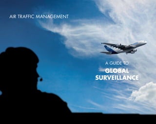


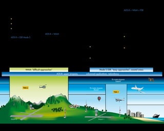


This document serves as a guide to global surveillance air traffic management, highlighting both traditional radar systems and modern technologies like ADS-B and multilateration. It emphasizes the importance of selecting the right surveillance solution based on specific operational environments, traffic forecasts, and budget constraints. Ultimately, it aims to enhance safety, efficiency, and cost-effectiveness in air traffic surveillance.