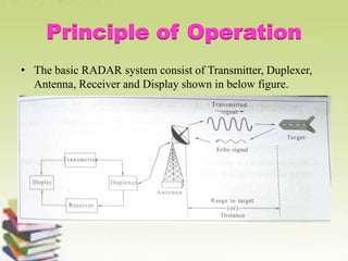
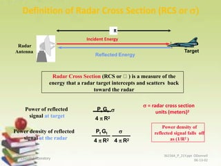
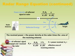
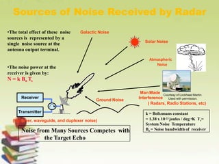
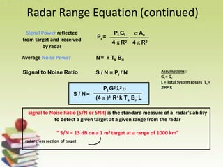
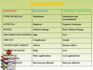
SlideShare a Scribd company logo
1 of 45
Download to read offline
Microwave Communications
and Television
Nenavath Ravi Kumar
Associate Professor
ECE Dept-MIST
Principles of RADAR
Systems
Contents
• Working Processes Of Radar
• History – BeforeRadar
• PrincipleOfOperation
• Radio Detection And Ranging
• Radar Functions
• Radar Bands And Usage
• Terminology Of Radar Systems
• Radar Range Equation
• Types Of Radar
• Pulse RADAR
• Duplexer Using Pin Switches
• Doppler Effect
• Principle Of Continuous Wave Radar
• Principles Of MTI RADAR
• Different Types Of RADAR & It’s Applications
 They send sound waves that reflect
of an object just as electric
RADAR systems do.
RADAR is an acronym for RAdio
Detecting And Ranging.
First successfully demonstrated in
1936.
It uses electromagnetic waves.
It enjoys wide range of application.
WORKING PROCESSES OF RADAR
History – Before Radar
■ Between the World Wars,
parabolic sound mirrors, were
used to provide early
warming;
■ Acoustic mirrors had a limited
effectiveness, and the
increasing speed of aircraft in
the 1930s meant that they
would already be too close to
deal with by the time they had
been detected.
■ Radio transmitters had already
been in use for over a decade
for communications.
WW1
WW2
Top: (L) Bombing during the WW1, (R)
“Whisper Dishes” Bottom: (L) WW2
Bombers, (R) Four-horn acoustic
locator,1930s
The history of RADAR starts with experiments by Heinrich &
Hertz in the late 19th century.
The first form of RADAR created by humans was the
telemobilescope.
Telemobilescope ( The first form of RADAR )
 It was mainly used to detect ships to avoid collisions
HISTROY
History – Radio Detection
■ Radar was first patented and
demonstrated in 1904 by the German
engineer Christian Hülsmeyer;
■ Watson Watt is generally credited with
initiating what would later be called radar;
■ In June 17, 1935, a radio-based detection
and ranging was first demonstrated in
Great Britain;
■ The first Radar system used by the
British
comprised 21 stations placed along the
country’s eastern coast.
Left: (T) Christian Hülsmeyer, (B) Watson
Watt, Right: Chain Home coverage map
Principle of Operation
• The basic RADAR system consist of Transmitter, Duplexer,
Antenna, Receiver and Display shown in below figure.
Transmitter: It generates high power signals at microwave
frequency range, radiated into space by using an Antenna through
Duplexer towards the target for detection.
Duplexer: It is a switch which connects the transmitter or receiver
to the Antenna alternately.
Antenna: The same Antenna can be used for transmitter &
Receiver, It is a transiver Antenna. Used for transmitting
electromagnetic waves towards target & receive echo signal from
target.
Receiver: The reflected signals (echo signals) collected by the
transiver antenna.
Display: It is designed to present the received information.
RADAR Display: A-Scope, B-Scope, Plan-Position Indicator (PPI)
etc.
Principle of Operation
 Reflection of electromagnetic waves
 Measurement of running time of transmitted pulses
• Bistatic: the transmit and receive antennas are at different
locations as viewed from the target (e.g., ground transmitter and
airborne receiver).
• Monostatic: the transmitter and receiver are colocated as viewed
from the target (i.e., the same antenna is used to transmit and
receive).
• Quasi-monostatic: the transmit and receive antennas are slightly
separated but still appear to be at the same location as viewed from
the target (e.g., separate transmit and receive antennas on same
aircraft).
Radio Detection and Ranging
TARGET
TRANSMITTER (TX)
RECEIVER (RX)
INCIDENT WAVE
FRONTS
SCATTERED WAVE
FRONTS
Rt
Rr

Radar Functions
• Normal radar functions:
1.range (from pulse delay)
2.velocity (from Doppler frequency shift)
3.angular direction (from antenna pointing)
• Signature analysis and inverse scattering:
4.target size (from magnitude of return)
5.target shape and components (return as a function
of direction)
6.moving parts (modulation of the return)
7.material composition
• The complexity (cost & size) of the radar
increases with the extent of the functions that the
radar performs.
WHY MICROWAVE ???
Very compact
High Gain
Highly directional
Antennas
Radio frequencies
Suitable for most
applications
6
Radar Bands and Usage
8
Fields of Applications
• Military Applications, Security,
Surveillances etc.
• Weather Observations.
• Air Traffic Control.
• RADAR Speed meter.
• Collision Avoidance RADARs.
• Inspection of Construction work.
• Road maintenances
Terminology of Radar Systems
• RANGE: The distance between Radar and target is called Range of
the target or simply range, R. We know that Radar transmits a signal to
the target and accordingly the target sends an echo signal to the Radar
with the speed of light, C.
Distance=Speed×Time
The two way distance between the Radar and target will be 2R
2R=C×T
R=C*T/2
• ECHO SIGNALS: The reflected electromagnetic signal from the
target is called “ECHO”.
• PULSE WIDTH (PW): it is the duration of the RADAR pulse. It
express in milliseconds.
• REST TIME (RT): It is the time interval between two pulses.
PULSE REPETITION TIME(PRT): It is the time interval between the
beginning of one pulse and beginning of next pulse.
It is the sum of Pulse Width (PW) and Rest Time (RT).
PRT = PW + RT
PULSE REPETITION FREQUENCY (PRF): The number of pulses transmitted
per second is called as PULSE REPETITION FREQUENCY .
It is the reciprocal of the pulse repetition time.
DUTY CYCLE (DC): It is the ratio of the Pulse width (PW) to the Pulse
Repetition Time (PRT).
Or
It is also defined as the product of Pulse Width and Pulse Repetition Frequency.
MAXIMUM UNAMBIGUOUS RANGE: The range beyond which targets
appear as second time around echoes is called as “Maximum Unambiguous
Range”.
Hence maximum unambiguous range is given by
RADOME: Radome is a sheltering structure for antenna which must be operated
in severe weather conditions (High winds, icing and extreme temperatures).
AZIMUTH & ELEVATION ANGLES OF THE TARGET:
Azimuth (Horizontal) Angle : It is antenna beam angle on the local horizontal
plane from same reference.
Elevation (Vertical) Angle: It is angle between RADAR antenna beam axis and
local horizontal.
Radar Range Equation
Pt
Power density from
uniformly radiating antenna
transmitting spherical wave
Pt = peak transmitter
power
R = distance from radar4  R2
R
Radar Range Equation (continued)
Power density from
isotropic antenna
Pt = peak transmitter
power
R = distance from radar
Pt
4  R2
Power density from
directive antenna
Pt Gt
Gt = transmitgain
4  R2
.
Gain is the radiation intensity of the
antenna in a given direction over
that of an isotropic (uniformly
radiating) source
Gain = 4  A / 2
Definition of Radar Cross Section (RCS or 
Radar Cross Section (RCS or ) is a measure of the
energy that a radar target intercepts and scatters back
toward the radar
Power of reflected
signal at target
t tP G 
4  R2
 = radar cross section
units (meters)2
Power density of reflected
signal at the radar
Pt Gt 
4  R2 4  R2
Power density of
reflected signal falls off
as (1/R2 )
Target
Radar
Antenna
Reflected Energy
R
Incident Energy
MIT Lincoln Laboratory
361564_P_21Y.ppt ODonnell
06-13-02
Radar Range Equation (continued)
Power density of reflected
signal at radar
Pt Gt 
4  R2 4  R2
Power of reflected signal
from target and received
by radar
Pt Gt
4  R2 4  R2
 Ae Pr = power received Ae =
effective area of
receiving antenna
rP =
The received power = the power density at the radar times the area of
the receiving antenna
Target
Radar
Antenna Reflected Energy
R
Sources of Noise Received by Radar
•The total effect of these noise
sources is represented by a
single noise source at the
antenna output terminal.
•The noise power at the
receiver is given by:
N = k Bn Ts
k = Boltzmans constant
= 1.38 x 10⁻²³ joules / deg oK Ts=
System Noise Temperature
Bn = Noise bandwidth of receiverNoise from Many Sources Competes with
the Target Echo
Transmitter
Receiver
Solar Noise
Galactic Noise
Man Made
Interference
Atmospheric
Noise
( Radars, Radio Stations, etc)
(Receiver, waveguide, and duplexer noise)
Ground Noise
Courtesy of Lockheed Martin.
Used with permission.
Radar Range Equation (continued)
Signal Power reflected
from target and received
by radar
Average Noise Power N= k Ts Bn
Signal to Noise Ratio S / N = Pr / N Assumptions :
Gt = Gr
L = Total System Losses To =
290o K
Pt Gt  Ae
4  R2 4  R2
rP =
Signal to Noise Ratio (S/N or SNR) is the standard measure of a radar’s ability
to detect a given target at a given range from the radar
“ S/N = 13 dB on a 1 m2 target at a range of 1000 km”
radar cross section of target
s n
Pt G2 2 
(4  3 R4k T B L
S / N=
Types Of Radar
Primary Radar
A Primary Radar transmits high-frequency signals
which are reflected at targets. The arisen echoes
are received and evaluated.
Secondary Radar
At these radar sets the target must have a
transponder (transmitting responder) on board
and this transponder responds to interrogation by
transmitting a coded reply signal.
Pulse RADAR
Block Diagram
Trigger Source: It provides pulses for the modulator. It is
also called synchronizer.
Pulse Modulator: It provides rectangular pulses which
acts as the supply voltage to the output tube.
Output Tube: It can be magnetron or reflux klystron or
TWT as per requirement. If an amplifier is used, a source
of microwave is also required.
Antenna: Usually Parabolic reflector antenna is used for
both transmission and reception.
Duplexer: It consists of two gas discharge tubes of fast
RF switches namely Anti Transmit Receiver (ATR) tube
and Transmit – Receiver (TR) tube.
Low Noise RF Amplifier: It is the first stage of the
receiver. It amplifies the received signal to desired level.
This is done by a TWT amplifier or parametric amplifier.
Mixer & Local Oscillator: These convert RF signal
output from RF amplifier to low frequency levels called
Intermediate Frequency. Thus in a mixer stage, the carrier
frequency is reduced.
IF Amplifier: It consists of cascade of tuned amplifiers
and provides high gain. IF range is 30MHz or 60MHz.
Detector: It demodulates the signals coming from the IF
amplifier and its output is given to the video amplifier.
Generally schottky diode is used for demodulating
received echo signals.
Video Amplifier: The output of the detector is amplified
by video amplifier to the specified level
Display: It provides visual information.
Advantages & Disadvantages of
Pulse RADAR
Advantages:
• It is simple in design & Operation.
• No need for accurate synchronization.
• Range can be increased by increasing. transmitted
power or by increasing diameter of parabolic reflector
of antenna.
Disadvantages:
• It cannot measure the velocity of moving target but
only can measure range.
• Clutters can cause several problems.
• Moving Target cannot be detected.
DUPLEXER USING PIN SWITCHES:
DUPLEXER USING CIRCULATOR:
DUPLEXER operation
• A branch type duplexer consists of two fast RF
switches are called
• Transmit – Receive (TR) Switch or TR Tube.
• Anti- Transmit – Receiver (ATR) Switch or ATR
Tube.
• The TR tube consists of resonant cavity associated
with the cathode tube. Tube itself contains an inert
gas (Helium or Neon) at low pressure.
• When gas tube is in operation, resonant cavity
permits energy to be transferred freely from input to
output line.
• An ATR tube is a TR tube with no output.
DOPPLER EFFECT
• The frequency shift in the received echo signal
in the RADAR due to the moving target is
known as “DOPPLER EFFECT”.
• The Doppler frequency shift (fd) is given by
• Where – Doppler shift frequency.
VR – Relative Velocity
λ – wavelength of the transmitted wave
Principle of Continuous Wave Radar
Principle of CW RADAR
• It uses the Doppler effect to detect frequency change caused by
a moving target and displays this as a relative velocity.
• The transmitted energy being continuous duplexer is replaced
by a circulator. Circulator provides isolation between the
transmitter and the receiver.
• The transmitted frequency ft is received as the target moves
from the RADAR.
• These incoming echo signals (ft±fd) are heterodyned with
locally generated transmitted signal (ft) inside a mixer.
• The output of the detector is applied to the Doppler amplifier. Is
to eliminate the echoes from the stationary targets and to
amplify the Doppler echo signals (fd).
• The indicator displays the velocity of the target.
Advantages & Disadvantages of CW
RADAR
Advantages:
• Accurate measurement of relative velocity of the target.
• Simple Circuit
• Low power consumption
• Small in size
• It is used at low transmitting power.
Disadvantages:
• It doesn’t give information about range.
• If large number of targets, it does not give accurate
results.
Principles of MTI RADAR
• MTI stands Moving Target Indicator RADAR.
• The system can determine moving target velocity
and to distinguish moving targets from stationary
targets.
• This RADAR uses the “Doppler effect” for its
operation.
• The basic principle of MTI RADAR is to compare
a set or received echoes with previous received
echoes and cancelling out the stationary or
permanent echoes. Whose phase remains
unchanged but moving targets will give change of
phase that’s why these are not cancelled.
Block Diagram of MTI RADAR
Blind speed
• If the target has uniform velocity, the
successive sweeps will have Doppler phase
shifts of exactly 2∏ radians and the target
appears as a stationary and gives wrong
indication.
• The speed corresponding to this condition is
called “Blind Speed”.
• The blind speed of the target is given by
Vb=PRF* nλ/2
Where n– any integer.
Different Types of RADARs
&
Applications
MIT Lincoln Laboratory
Introduction-14
AG 6/18/02
Surveillance and Fire Control Radars
Courtesy of
Raytheon. Used
with permission.
Courtesy of
Raytheon. Used with
permission.
Courtesy of
Raytheon. Used with
permission.
Courtesy of
Raytheon. Used
with permission.
Courtesy of
Raytheon. Used
with permission.
Photo courtesy of
IIT Corporation used
the permission
.
Courtesy of Global
Security. Used
with permission.
Courtesy of US
Navy.
MIT Lincoln Laboratory
Introduction-15
AG 6/18/02
Airborne and Air Traffic Control Radars
Courtesy of Northrop
Grumman. Used with
permission.
Courtesy of US
Navy.
Courtesy of US Air
Force.
Courtesy of US
Air Force.
Courtesy of US
Air Force.
Courtesy Lincoln
Laboratory.
Courtesy of US
Air Force.
MIT Lincoln Laboratory
Introduction-16
AG 6/18/02
Instrumentation Radars
Comparison
PARAMETER PULSE RADAR CONTINOUS WAVE RADAR
TYPE OF SIGNAL Modulated Modulated and
Unmodulated
ANTENNA Duplexer Separate Antennas
RANGE Indicates Range Don't indicate Range
TRANSMITTING POWER high Low
CIRCUIT Complicated Simple
STATIONARY TARGET Affects Doesn't affect
MAXIMUM RANGE High Low
PRACTICAL
APPLICATION
More applications Less applications
MANY TARGETS Does not get affected Does get affected
Principles of RADAR Systems

More Related Content

What's hot (20)

Radar system
Radar systemRadar system
Radar system
 
Radar
RadarRadar
Radar
 
RADAR
RADARRADAR
RADAR
 
Radar Basics
Radar BasicsRadar Basics
Radar Basics
 
Radar presentation
Radar presentation Radar presentation
Radar presentation
 
radar
radarradar
radar
 
Radar ppt
Radar pptRadar ppt
Radar ppt
 
Radar fundamentals
Radar fundamentalsRadar fundamentals
Radar fundamentals
 
Synthetic aperture radar
Synthetic aperture radar Synthetic aperture radar
Synthetic aperture radar
 
radar
 radar radar
radar
 
radar-ppt
radar-pptradar-ppt
radar-ppt
 
Lec3
Lec3Lec3
Lec3
 
Components of a Pulse Radar System
Components of a Pulse Radar SystemComponents of a Pulse Radar System
Components of a Pulse Radar System
 
Radar
RadarRadar
Radar
 
radar principles
   radar principles    radar principles
radar principles
 
Radar communication
Radar communicationRadar communication
Radar communication
 
radar
 radar radar
radar
 
Radar
RadarRadar
Radar
 
Study of Radar System PPT
Study of Radar System PPTStudy of Radar System PPT
Study of Radar System PPT
 
Introduction to radar
Introduction to radarIntroduction to radar
Introduction to radar
 

Similar to Principles of RADAR Systems

Radarsurvbw 1232267772428796-3
Radarsurvbw 1232267772428796-3Radarsurvbw 1232267772428796-3
Radarsurvbw 1232267772428796-3RRFF
 
chandra shekhar_Unit 2 _Radar_ feb 4 2016
chandra shekhar_Unit 2 _Radar_ feb 4 2016chandra shekhar_Unit 2 _Radar_ feb 4 2016
chandra shekhar_Unit 2 _Radar_ feb 4 2016CHANDRA SHEKHAR
 
Radar Systems- Unit- I : Basics of Radar
Radar Systems- Unit- I : Basics of Radar Radar Systems- Unit- I : Basics of Radar
Radar Systems- Unit- I : Basics of Radar VenkataRatnam14
 
Radar 2009 a 4 radar equation
Radar 2009 a  4 radar equationRadar 2009 a  4 radar equation
Radar 2009 a 4 radar equationVi Binh Q. Le
 
Radar 2009 a 4 radar equation
Radar 2009 a  4 radar equationRadar 2009 a  4 radar equation
Radar 2009 a 4 radar equationForward2025
 
Radar is a detection system that uses radio waves to determine the range, ang...
Radar is a detection system that uses radio waves to determine the range, ang...Radar is a detection system that uses radio waves to determine the range, ang...
Radar is a detection system that uses radio waves to determine the range, ang...vijay525469
 
Introduction Radar signal processing.pdf
Introduction Radar signal processing.pdfIntroduction Radar signal processing.pdf
Introduction Radar signal processing.pdfRaoni13
 
Prediction of range performance
Prediction of range performancePrediction of range performance
Prediction of range performancebhupender rawat
 
chapter 1radar introduction .pptx
chapter 1radar introduction .pptxchapter 1radar introduction .pptx
chapter 1radar introduction .pptxbewnet
 
Radar Systems for NTU, 1 Nov 2014
Radar Systems for NTU, 1 Nov 2014Radar Systems for NTU, 1 Nov 2014
Radar Systems for NTU, 1 Nov 2014TBSS Group
 
Introduction to radars
Introduction to radarsIntroduction to radars
Introduction to radarsTARUN CHOPRA
 
Radar Presentation
Radar PresentationRadar Presentation
Radar PresentationAIM iTech
 
Subsystems of radar and signal processing
Subsystems of radar and signal processing Subsystems of radar and signal processing
Subsystems of radar and signal processing Ronak Vyas
 
LOW,MEDIUM,HIGH_Doppler_MTI.pptx
LOW,MEDIUM,HIGH_Doppler_MTI.pptxLOW,MEDIUM,HIGH_Doppler_MTI.pptx
LOW,MEDIUM,HIGH_Doppler_MTI.pptxFirstknightPhyo
 

Similar to Principles of RADAR Systems (20)

Radarsurvbw 1232267772428796-3
Radarsurvbw 1232267772428796-3Radarsurvbw 1232267772428796-3
Radarsurvbw 1232267772428796-3
 
chandra shekhar_Unit 2 _Radar_ feb 4 2016
chandra shekhar_Unit 2 _Radar_ feb 4 2016chandra shekhar_Unit 2 _Radar_ feb 4 2016
chandra shekhar_Unit 2 _Radar_ feb 4 2016
 
Radar Systems- Unit- I : Basics of Radar
Radar Systems- Unit- I : Basics of Radar Radar Systems- Unit- I : Basics of Radar
Radar Systems- Unit- I : Basics of Radar
 
RADAR SYSTEMS
RADAR SYSTEMSRADAR SYSTEMS
RADAR SYSTEMS
 
IARE_RS_PPT_0.pdf
IARE_RS_PPT_0.pdfIARE_RS_PPT_0.pdf
IARE_RS_PPT_0.pdf
 
7364382 Radar System
7364382 Radar System7364382 Radar System
7364382 Radar System
 
Radar 2009 a 4 radar equation
Radar 2009 a  4 radar equationRadar 2009 a  4 radar equation
Radar 2009 a 4 radar equation
 
Radar 2009 a 4 radar equation
Radar 2009 a  4 radar equationRadar 2009 a  4 radar equation
Radar 2009 a 4 radar equation
 
Radar is a detection system that uses radio waves to determine the range, ang...
Radar is a detection system that uses radio waves to determine the range, ang...Radar is a detection system that uses radio waves to determine the range, ang...
Radar is a detection system that uses radio waves to determine the range, ang...
 
Introduction Radar signal processing.pdf
Introduction Radar signal processing.pdfIntroduction Radar signal processing.pdf
Introduction Radar signal processing.pdf
 
RADAR Basics
RADAR BasicsRADAR Basics
RADAR Basics
 
Prediction of range performance
Prediction of range performancePrediction of range performance
Prediction of range performance
 
Report on radar
Report on radarReport on radar
Report on radar
 
chapter 1radar introduction .pptx
chapter 1radar introduction .pptxchapter 1radar introduction .pptx
chapter 1radar introduction .pptx
 
Radar Systems for NTU, 1 Nov 2014
Radar Systems for NTU, 1 Nov 2014Radar Systems for NTU, 1 Nov 2014
Radar Systems for NTU, 1 Nov 2014
 
Introduction to radars
Introduction to radarsIntroduction to radars
Introduction to radars
 
Radar Presentation
Radar PresentationRadar Presentation
Radar Presentation
 
PPT.ppt
PPT.pptPPT.ppt
PPT.ppt
 
Subsystems of radar and signal processing
Subsystems of radar and signal processing Subsystems of radar and signal processing
Subsystems of radar and signal processing
 
LOW,MEDIUM,HIGH_Doppler_MTI.pptx
LOW,MEDIUM,HIGH_Doppler_MTI.pptxLOW,MEDIUM,HIGH_Doppler_MTI.pptx
LOW,MEDIUM,HIGH_Doppler_MTI.pptx
 

Recently uploaded

80 ĐỀ THI THỬ TUYỂN SINH TIẾNG ANH VÀO 10 SỞ GD – ĐT THÀNH PHỐ HỒ CHÍ MINH NĂ...
80 ĐỀ THI THỬ TUYỂN SINH TIẾNG ANH VÀO 10 SỞ GD – ĐT THÀNH PHỐ HỒ CHÍ MINH NĂ...80 ĐỀ THI THỬ TUYỂN SINH TIẾNG ANH VÀO 10 SỞ GD – ĐT THÀNH PHỐ HỒ CHÍ MINH NĂ...
80 ĐỀ THI THỬ TUYỂN SINH TIẾNG ANH VÀO 10 SỞ GD – ĐT THÀNH PHỐ HỒ CHÍ MINH NĂ...Nguyen Thanh Tu Collection
 
The basics of sentences session 3pptx.pptx
The basics of sentences session 3pptx.pptxThe basics of sentences session 3pptx.pptx
The basics of sentences session 3pptx.pptxheathfieldcps1
 
Accessible Digital Futures project (20/03/2024)
Accessible Digital Futures project (20/03/2024)Accessible Digital Futures project (20/03/2024)
Accessible Digital Futures project (20/03/2024)Jisc
 
Python Notes for mca i year students osmania university.docx
Python Notes for mca i year students osmania university.docxPython Notes for mca i year students osmania university.docx
Python Notes for mca i year students osmania university.docxRamakrishna Reddy Bijjam
 
Understanding Accommodations and Modifications
Understanding  Accommodations and ModificationsUnderstanding  Accommodations and Modifications
Understanding Accommodations and ModificationsMJDuyan
 
Model Attribute _rec_name in the Odoo 17
Model Attribute _rec_name in the Odoo 17Model Attribute _rec_name in the Odoo 17
Model Attribute _rec_name in the Odoo 17Celine George
 
REMIFENTANIL: An Ultra short acting opioid.pptx
REMIFENTANIL: An Ultra short acting opioid.pptxREMIFENTANIL: An Ultra short acting opioid.pptx
REMIFENTANIL: An Ultra short acting opioid.pptxDr. Ravikiran H M Gowda
 
QUATER-1-PE-HEALTH-LC2- this is just a sample of unpacked lesson
QUATER-1-PE-HEALTH-LC2- this is just a sample of unpacked lessonQUATER-1-PE-HEALTH-LC2- this is just a sample of unpacked lesson
QUATER-1-PE-HEALTH-LC2- this is just a sample of unpacked lessonhttgc7rh9c
 
Exploring_the_Narrative_Style_of_Amitav_Ghoshs_Gun_Island.pptx
Exploring_the_Narrative_Style_of_Amitav_Ghoshs_Gun_Island.pptxExploring_the_Narrative_Style_of_Amitav_Ghoshs_Gun_Island.pptx
Exploring_the_Narrative_Style_of_Amitav_Ghoshs_Gun_Island.pptxPooja Bhuva
 
TỔNG ÔN TẬP THI VÀO LỚP 10 MÔN TIẾNG ANH NĂM HỌC 2023 - 2024 CÓ ĐÁP ÁN (NGỮ Â...
TỔNG ÔN TẬP THI VÀO LỚP 10 MÔN TIẾNG ANH NĂM HỌC 2023 - 2024 CÓ ĐÁP ÁN (NGỮ Â...TỔNG ÔN TẬP THI VÀO LỚP 10 MÔN TIẾNG ANH NĂM HỌC 2023 - 2024 CÓ ĐÁP ÁN (NGỮ Â...
TỔNG ÔN TẬP THI VÀO LỚP 10 MÔN TIẾNG ANH NĂM HỌC 2023 - 2024 CÓ ĐÁP ÁN (NGỮ Â...Nguyen Thanh Tu Collection
 
How to Add New Custom Addons Path in Odoo 17
How to Add New Custom Addons Path in Odoo 17How to Add New Custom Addons Path in Odoo 17
How to Add New Custom Addons Path in Odoo 17Celine George
 
Transparency, Recognition and the role of eSealing - Ildiko Mazar and Koen No...
Transparency, Recognition and the role of eSealing - Ildiko Mazar and Koen No...Transparency, Recognition and the role of eSealing - Ildiko Mazar and Koen No...
Transparency, Recognition and the role of eSealing - Ildiko Mazar and Koen No...EADTU
 
Details on CBSE Compartment Exam.pptx1111
Details on CBSE Compartment Exam.pptx1111Details on CBSE Compartment Exam.pptx1111
Details on CBSE Compartment Exam.pptx1111GangaMaiya1
 
FICTIONAL SALESMAN/SALESMAN SNSW 2024.pdf
FICTIONAL SALESMAN/SALESMAN SNSW 2024.pdfFICTIONAL SALESMAN/SALESMAN SNSW 2024.pdf
FICTIONAL SALESMAN/SALESMAN SNSW 2024.pdfPondicherry University
 
Tatlong Kwento ni Lola basyang-1.pdf arts
Tatlong Kwento ni Lola basyang-1.pdf artsTatlong Kwento ni Lola basyang-1.pdf arts
Tatlong Kwento ni Lola basyang-1.pdf artsNbelano25
 
Sensory_Experience_and_Emotional_Resonance_in_Gabriel_Okaras_The_Piano_and_Th...
Sensory_Experience_and_Emotional_Resonance_in_Gabriel_Okaras_The_Piano_and_Th...Sensory_Experience_and_Emotional_Resonance_in_Gabriel_Okaras_The_Piano_and_Th...
Sensory_Experience_and_Emotional_Resonance_in_Gabriel_Okaras_The_Piano_and_Th...Pooja Bhuva
 
NO1 Top Black Magic Specialist In Lahore Black magic In Pakistan Kala Ilam Ex...
NO1 Top Black Magic Specialist In Lahore Black magic In Pakistan Kala Ilam Ex...NO1 Top Black Magic Specialist In Lahore Black magic In Pakistan Kala Ilam Ex...
NO1 Top Black Magic Specialist In Lahore Black magic In Pakistan Kala Ilam Ex...Amil baba
 
dusjagr & nano talk on open tools for agriculture research and learning
dusjagr & nano talk on open tools for agriculture research and learningdusjagr & nano talk on open tools for agriculture research and learning
dusjagr & nano talk on open tools for agriculture research and learningMarc Dusseiller Dusjagr
 
Interdisciplinary_Insights_Data_Collection_Methods.pptx
Interdisciplinary_Insights_Data_Collection_Methods.pptxInterdisciplinary_Insights_Data_Collection_Methods.pptx
Interdisciplinary_Insights_Data_Collection_Methods.pptxPooja Bhuva
 
21st_Century_Skills_Framework_Final_Presentation_2.pptx
21st_Century_Skills_Framework_Final_Presentation_2.pptx21st_Century_Skills_Framework_Final_Presentation_2.pptx
21st_Century_Skills_Framework_Final_Presentation_2.pptxJoelynRubio1
 

Recently uploaded (20)

80 ĐỀ THI THỬ TUYỂN SINH TIẾNG ANH VÀO 10 SỞ GD – ĐT THÀNH PHỐ HỒ CHÍ MINH NĂ...
80 ĐỀ THI THỬ TUYỂN SINH TIẾNG ANH VÀO 10 SỞ GD – ĐT THÀNH PHỐ HỒ CHÍ MINH NĂ...80 ĐỀ THI THỬ TUYỂN SINH TIẾNG ANH VÀO 10 SỞ GD – ĐT THÀNH PHỐ HỒ CHÍ MINH NĂ...
80 ĐỀ THI THỬ TUYỂN SINH TIẾNG ANH VÀO 10 SỞ GD – ĐT THÀNH PHỐ HỒ CHÍ MINH NĂ...
 
The basics of sentences session 3pptx.pptx
The basics of sentences session 3pptx.pptxThe basics of sentences session 3pptx.pptx
The basics of sentences session 3pptx.pptx
 
Accessible Digital Futures project (20/03/2024)
Accessible Digital Futures project (20/03/2024)Accessible Digital Futures project (20/03/2024)
Accessible Digital Futures project (20/03/2024)
 
Python Notes for mca i year students osmania university.docx
Python Notes for mca i year students osmania university.docxPython Notes for mca i year students osmania university.docx
Python Notes for mca i year students osmania university.docx
 
Understanding Accommodations and Modifications
Understanding  Accommodations and ModificationsUnderstanding  Accommodations and Modifications
Understanding Accommodations and Modifications
 
Model Attribute _rec_name in the Odoo 17
Model Attribute _rec_name in the Odoo 17Model Attribute _rec_name in the Odoo 17
Model Attribute _rec_name in the Odoo 17
 
REMIFENTANIL: An Ultra short acting opioid.pptx
REMIFENTANIL: An Ultra short acting opioid.pptxREMIFENTANIL: An Ultra short acting opioid.pptx
REMIFENTANIL: An Ultra short acting opioid.pptx
 
QUATER-1-PE-HEALTH-LC2- this is just a sample of unpacked lesson
QUATER-1-PE-HEALTH-LC2- this is just a sample of unpacked lessonQUATER-1-PE-HEALTH-LC2- this is just a sample of unpacked lesson
QUATER-1-PE-HEALTH-LC2- this is just a sample of unpacked lesson
 
Exploring_the_Narrative_Style_of_Amitav_Ghoshs_Gun_Island.pptx
Exploring_the_Narrative_Style_of_Amitav_Ghoshs_Gun_Island.pptxExploring_the_Narrative_Style_of_Amitav_Ghoshs_Gun_Island.pptx
Exploring_the_Narrative_Style_of_Amitav_Ghoshs_Gun_Island.pptx
 
TỔNG ÔN TẬP THI VÀO LỚP 10 MÔN TIẾNG ANH NĂM HỌC 2023 - 2024 CÓ ĐÁP ÁN (NGỮ Â...
TỔNG ÔN TẬP THI VÀO LỚP 10 MÔN TIẾNG ANH NĂM HỌC 2023 - 2024 CÓ ĐÁP ÁN (NGỮ Â...TỔNG ÔN TẬP THI VÀO LỚP 10 MÔN TIẾNG ANH NĂM HỌC 2023 - 2024 CÓ ĐÁP ÁN (NGỮ Â...
TỔNG ÔN TẬP THI VÀO LỚP 10 MÔN TIẾNG ANH NĂM HỌC 2023 - 2024 CÓ ĐÁP ÁN (NGỮ Â...
 
How to Add New Custom Addons Path in Odoo 17
How to Add New Custom Addons Path in Odoo 17How to Add New Custom Addons Path in Odoo 17
How to Add New Custom Addons Path in Odoo 17
 
Transparency, Recognition and the role of eSealing - Ildiko Mazar and Koen No...
Transparency, Recognition and the role of eSealing - Ildiko Mazar and Koen No...Transparency, Recognition and the role of eSealing - Ildiko Mazar and Koen No...
Transparency, Recognition and the role of eSealing - Ildiko Mazar and Koen No...
 
Details on CBSE Compartment Exam.pptx1111
Details on CBSE Compartment Exam.pptx1111Details on CBSE Compartment Exam.pptx1111
Details on CBSE Compartment Exam.pptx1111
 
FICTIONAL SALESMAN/SALESMAN SNSW 2024.pdf
FICTIONAL SALESMAN/SALESMAN SNSW 2024.pdfFICTIONAL SALESMAN/SALESMAN SNSW 2024.pdf
FICTIONAL SALESMAN/SALESMAN SNSW 2024.pdf
 
Tatlong Kwento ni Lola basyang-1.pdf arts
Tatlong Kwento ni Lola basyang-1.pdf artsTatlong Kwento ni Lola basyang-1.pdf arts
Tatlong Kwento ni Lola basyang-1.pdf arts
 
Sensory_Experience_and_Emotional_Resonance_in_Gabriel_Okaras_The_Piano_and_Th...
Sensory_Experience_and_Emotional_Resonance_in_Gabriel_Okaras_The_Piano_and_Th...Sensory_Experience_and_Emotional_Resonance_in_Gabriel_Okaras_The_Piano_and_Th...
Sensory_Experience_and_Emotional_Resonance_in_Gabriel_Okaras_The_Piano_and_Th...
 
NO1 Top Black Magic Specialist In Lahore Black magic In Pakistan Kala Ilam Ex...
NO1 Top Black Magic Specialist In Lahore Black magic In Pakistan Kala Ilam Ex...NO1 Top Black Magic Specialist In Lahore Black magic In Pakistan Kala Ilam Ex...
NO1 Top Black Magic Specialist In Lahore Black magic In Pakistan Kala Ilam Ex...
 
dusjagr & nano talk on open tools for agriculture research and learning
dusjagr & nano talk on open tools for agriculture research and learningdusjagr & nano talk on open tools for agriculture research and learning
dusjagr & nano talk on open tools for agriculture research and learning
 
Interdisciplinary_Insights_Data_Collection_Methods.pptx
Interdisciplinary_Insights_Data_Collection_Methods.pptxInterdisciplinary_Insights_Data_Collection_Methods.pptx
Interdisciplinary_Insights_Data_Collection_Methods.pptx
 
21st_Century_Skills_Framework_Final_Presentation_2.pptx
21st_Century_Skills_Framework_Final_Presentation_2.pptx21st_Century_Skills_Framework_Final_Presentation_2.pptx
21st_Century_Skills_Framework_Final_Presentation_2.pptx
 

Principles of RADAR Systems

  • 1. Microwave Communications and Television Nenavath Ravi Kumar Associate Professor ECE Dept-MIST
  • 3. Contents • Working Processes Of Radar • History – BeforeRadar • PrincipleOfOperation • Radio Detection And Ranging • Radar Functions • Radar Bands And Usage • Terminology Of Radar Systems • Radar Range Equation • Types Of Radar • Pulse RADAR • Duplexer Using Pin Switches • Doppler Effect • Principle Of Continuous Wave Radar • Principles Of MTI RADAR • Different Types Of RADAR & It’s Applications
  • 4.  They send sound waves that reflect of an object just as electric RADAR systems do. RADAR is an acronym for RAdio Detecting And Ranging. First successfully demonstrated in 1936. It uses electromagnetic waves. It enjoys wide range of application. WORKING PROCESSES OF RADAR
  • 5. History – Before Radar ■ Between the World Wars, parabolic sound mirrors, were used to provide early warming; ■ Acoustic mirrors had a limited effectiveness, and the increasing speed of aircraft in the 1930s meant that they would already be too close to deal with by the time they had been detected. ■ Radio transmitters had already been in use for over a decade for communications. WW1 WW2 Top: (L) Bombing during the WW1, (R) “Whisper Dishes” Bottom: (L) WW2 Bombers, (R) Four-horn acoustic locator,1930s
  • 6. The history of RADAR starts with experiments by Heinrich & Hertz in the late 19th century. The first form of RADAR created by humans was the telemobilescope. Telemobilescope ( The first form of RADAR )  It was mainly used to detect ships to avoid collisions HISTROY
  • 7. History – Radio Detection ■ Radar was first patented and demonstrated in 1904 by the German engineer Christian Hülsmeyer; ■ Watson Watt is generally credited with initiating what would later be called radar; ■ In June 17, 1935, a radio-based detection and ranging was first demonstrated in Great Britain; ■ The first Radar system used by the British comprised 21 stations placed along the country’s eastern coast. Left: (T) Christian Hülsmeyer, (B) Watson Watt, Right: Chain Home coverage map
  • 8. Principle of Operation • The basic RADAR system consist of Transmitter, Duplexer, Antenna, Receiver and Display shown in below figure.
  • 9. Transmitter: It generates high power signals at microwave frequency range, radiated into space by using an Antenna through Duplexer towards the target for detection. Duplexer: It is a switch which connects the transmitter or receiver to the Antenna alternately. Antenna: The same Antenna can be used for transmitter & Receiver, It is a transiver Antenna. Used for transmitting electromagnetic waves towards target & receive echo signal from target. Receiver: The reflected signals (echo signals) collected by the transiver antenna. Display: It is designed to present the received information. RADAR Display: A-Scope, B-Scope, Plan-Position Indicator (PPI) etc.
  • 10. Principle of Operation  Reflection of electromagnetic waves  Measurement of running time of transmitted pulses
  • 11. • Bistatic: the transmit and receive antennas are at different locations as viewed from the target (e.g., ground transmitter and airborne receiver). • Monostatic: the transmitter and receiver are colocated as viewed from the target (i.e., the same antenna is used to transmit and receive). • Quasi-monostatic: the transmit and receive antennas are slightly separated but still appear to be at the same location as viewed from the target (e.g., separate transmit and receive antennas on same aircraft). Radio Detection and Ranging TARGET TRANSMITTER (TX) RECEIVER (RX) INCIDENT WAVE FRONTS SCATTERED WAVE FRONTS Rt Rr 
  • 12. Radar Functions • Normal radar functions: 1.range (from pulse delay) 2.velocity (from Doppler frequency shift) 3.angular direction (from antenna pointing) • Signature analysis and inverse scattering: 4.target size (from magnitude of return) 5.target shape and components (return as a function of direction) 6.moving parts (modulation of the return) 7.material composition • The complexity (cost & size) of the radar increases with the extent of the functions that the radar performs.
  • 13. WHY MICROWAVE ??? Very compact High Gain Highly directional Antennas Radio frequencies Suitable for most applications
  • 14. 6 Radar Bands and Usage 8
  • 15. Fields of Applications • Military Applications, Security, Surveillances etc. • Weather Observations. • Air Traffic Control. • RADAR Speed meter. • Collision Avoidance RADARs. • Inspection of Construction work. • Road maintenances
  • 16. Terminology of Radar Systems • RANGE: The distance between Radar and target is called Range of the target or simply range, R. We know that Radar transmits a signal to the target and accordingly the target sends an echo signal to the Radar with the speed of light, C. Distance=Speed×Time The two way distance between the Radar and target will be 2R 2R=C×T R=C*T/2 • ECHO SIGNALS: The reflected electromagnetic signal from the target is called “ECHO”. • PULSE WIDTH (PW): it is the duration of the RADAR pulse. It express in milliseconds. • REST TIME (RT): It is the time interval between two pulses.
  • 17. PULSE REPETITION TIME(PRT): It is the time interval between the beginning of one pulse and beginning of next pulse. It is the sum of Pulse Width (PW) and Rest Time (RT). PRT = PW + RT PULSE REPETITION FREQUENCY (PRF): The number of pulses transmitted per second is called as PULSE REPETITION FREQUENCY . It is the reciprocal of the pulse repetition time. DUTY CYCLE (DC): It is the ratio of the Pulse width (PW) to the Pulse Repetition Time (PRT). Or It is also defined as the product of Pulse Width and Pulse Repetition Frequency.
  • 18. MAXIMUM UNAMBIGUOUS RANGE: The range beyond which targets appear as second time around echoes is called as “Maximum Unambiguous Range”. Hence maximum unambiguous range is given by RADOME: Radome is a sheltering structure for antenna which must be operated in severe weather conditions (High winds, icing and extreme temperatures). AZIMUTH & ELEVATION ANGLES OF THE TARGET: Azimuth (Horizontal) Angle : It is antenna beam angle on the local horizontal plane from same reference. Elevation (Vertical) Angle: It is angle between RADAR antenna beam axis and local horizontal.
  • 19. Radar Range Equation Pt Power density from uniformly radiating antenna transmitting spherical wave Pt = peak transmitter power R = distance from radar4  R2 R
  • 20. Radar Range Equation (continued) Power density from isotropic antenna Pt = peak transmitter power R = distance from radar Pt 4  R2 Power density from directive antenna Pt Gt Gt = transmitgain 4  R2 . Gain is the radiation intensity of the antenna in a given direction over that of an isotropic (uniformly radiating) source Gain = 4  A / 2
  • 21. Definition of Radar Cross Section (RCS or  Radar Cross Section (RCS or ) is a measure of the energy that a radar target intercepts and scatters back toward the radar Power of reflected signal at target t tP G  4  R2  = radar cross section units (meters)2 Power density of reflected signal at the radar Pt Gt  4  R2 4  R2 Power density of reflected signal falls off as (1/R2 ) Target Radar Antenna Reflected Energy R Incident Energy MIT Lincoln Laboratory 361564_P_21Y.ppt ODonnell 06-13-02
  • 22. Radar Range Equation (continued) Power density of reflected signal at radar Pt Gt  4  R2 4  R2 Power of reflected signal from target and received by radar Pt Gt 4  R2 4  R2  Ae Pr = power received Ae = effective area of receiving antenna rP = The received power = the power density at the radar times the area of the receiving antenna Target Radar Antenna Reflected Energy R
  • 23. Sources of Noise Received by Radar •The total effect of these noise sources is represented by a single noise source at the antenna output terminal. •The noise power at the receiver is given by: N = k Bn Ts k = Boltzmans constant = 1.38 x 10⁻²³ joules / deg oK Ts= System Noise Temperature Bn = Noise bandwidth of receiverNoise from Many Sources Competes with the Target Echo Transmitter Receiver Solar Noise Galactic Noise Man Made Interference Atmospheric Noise ( Radars, Radio Stations, etc) (Receiver, waveguide, and duplexer noise) Ground Noise Courtesy of Lockheed Martin. Used with permission.
  • 24. Radar Range Equation (continued) Signal Power reflected from target and received by radar Average Noise Power N= k Ts Bn Signal to Noise Ratio S / N = Pr / N Assumptions : Gt = Gr L = Total System Losses To = 290o K Pt Gt  Ae 4  R2 4  R2 rP = Signal to Noise Ratio (S/N or SNR) is the standard measure of a radar’s ability to detect a given target at a given range from the radar “ S/N = 13 dB on a 1 m2 target at a range of 1000 km” radar cross section of target s n Pt G2 2  (4  3 R4k T B L S / N=
  • 26. Primary Radar A Primary Radar transmits high-frequency signals which are reflected at targets. The arisen echoes are received and evaluated. Secondary Radar At these radar sets the target must have a transponder (transmitting responder) on board and this transponder responds to interrogation by transmitting a coded reply signal.
  • 28. Trigger Source: It provides pulses for the modulator. It is also called synchronizer. Pulse Modulator: It provides rectangular pulses which acts as the supply voltage to the output tube. Output Tube: It can be magnetron or reflux klystron or TWT as per requirement. If an amplifier is used, a source of microwave is also required. Antenna: Usually Parabolic reflector antenna is used for both transmission and reception. Duplexer: It consists of two gas discharge tubes of fast RF switches namely Anti Transmit Receiver (ATR) tube and Transmit – Receiver (TR) tube. Low Noise RF Amplifier: It is the first stage of the receiver. It amplifies the received signal to desired level. This is done by a TWT amplifier or parametric amplifier.
  • 29. Mixer & Local Oscillator: These convert RF signal output from RF amplifier to low frequency levels called Intermediate Frequency. Thus in a mixer stage, the carrier frequency is reduced. IF Amplifier: It consists of cascade of tuned amplifiers and provides high gain. IF range is 30MHz or 60MHz. Detector: It demodulates the signals coming from the IF amplifier and its output is given to the video amplifier. Generally schottky diode is used for demodulating received echo signals. Video Amplifier: The output of the detector is amplified by video amplifier to the specified level Display: It provides visual information.
  • 30. Advantages & Disadvantages of Pulse RADAR Advantages: • It is simple in design & Operation. • No need for accurate synchronization. • Range can be increased by increasing. transmitted power or by increasing diameter of parabolic reflector of antenna. Disadvantages: • It cannot measure the velocity of moving target but only can measure range. • Clutters can cause several problems. • Moving Target cannot be detected.
  • 31. DUPLEXER USING PIN SWITCHES: DUPLEXER USING CIRCULATOR:
  • 32. DUPLEXER operation • A branch type duplexer consists of two fast RF switches are called • Transmit – Receive (TR) Switch or TR Tube. • Anti- Transmit – Receiver (ATR) Switch or ATR Tube. • The TR tube consists of resonant cavity associated with the cathode tube. Tube itself contains an inert gas (Helium or Neon) at low pressure. • When gas tube is in operation, resonant cavity permits energy to be transferred freely from input to output line. • An ATR tube is a TR tube with no output.
  • 33. DOPPLER EFFECT • The frequency shift in the received echo signal in the RADAR due to the moving target is known as “DOPPLER EFFECT”. • The Doppler frequency shift (fd) is given by • Where – Doppler shift frequency. VR – Relative Velocity λ – wavelength of the transmitted wave
  • 35. Principle of CW RADAR • It uses the Doppler effect to detect frequency change caused by a moving target and displays this as a relative velocity. • The transmitted energy being continuous duplexer is replaced by a circulator. Circulator provides isolation between the transmitter and the receiver. • The transmitted frequency ft is received as the target moves from the RADAR. • These incoming echo signals (ft±fd) are heterodyned with locally generated transmitted signal (ft) inside a mixer. • The output of the detector is applied to the Doppler amplifier. Is to eliminate the echoes from the stationary targets and to amplify the Doppler echo signals (fd). • The indicator displays the velocity of the target.
  • 36. Advantages & Disadvantages of CW RADAR Advantages: • Accurate measurement of relative velocity of the target. • Simple Circuit • Low power consumption • Small in size • It is used at low transmitting power. Disadvantages: • It doesn’t give information about range. • If large number of targets, it does not give accurate results.
  • 37. Principles of MTI RADAR • MTI stands Moving Target Indicator RADAR. • The system can determine moving target velocity and to distinguish moving targets from stationary targets. • This RADAR uses the “Doppler effect” for its operation. • The basic principle of MTI RADAR is to compare a set or received echoes with previous received echoes and cancelling out the stationary or permanent echoes. Whose phase remains unchanged but moving targets will give change of phase that’s why these are not cancelled.
  • 38. Block Diagram of MTI RADAR
  • 39. Blind speed • If the target has uniform velocity, the successive sweeps will have Doppler phase shifts of exactly 2∏ radians and the target appears as a stationary and gives wrong indication. • The speed corresponding to this condition is called “Blind Speed”. • The blind speed of the target is given by Vb=PRF* nλ/2 Where n– any integer.
  • 40. Different Types of RADARs & Applications
  • 41. MIT Lincoln Laboratory Introduction-14 AG 6/18/02 Surveillance and Fire Control Radars Courtesy of Raytheon. Used with permission. Courtesy of Raytheon. Used with permission. Courtesy of Raytheon. Used with permission. Courtesy of Raytheon. Used with permission. Courtesy of Raytheon. Used with permission. Photo courtesy of IIT Corporation used the permission . Courtesy of Global Security. Used with permission. Courtesy of US Navy.
  • 42. MIT Lincoln Laboratory Introduction-15 AG 6/18/02 Airborne and Air Traffic Control Radars Courtesy of Northrop Grumman. Used with permission. Courtesy of US Navy. Courtesy of US Air Force. Courtesy of US Air Force. Courtesy of US Air Force. Courtesy Lincoln Laboratory. Courtesy of US Air Force.
  • 43. MIT Lincoln Laboratory Introduction-16 AG 6/18/02 Instrumentation Radars
  • 44. Comparison PARAMETER PULSE RADAR CONTINOUS WAVE RADAR TYPE OF SIGNAL Modulated Modulated and Unmodulated ANTENNA Duplexer Separate Antennas RANGE Indicates Range Don't indicate Range TRANSMITTING POWER high Low CIRCUIT Complicated Simple STATIONARY TARGET Affects Doesn't affect MAXIMUM RANGE High Low PRACTICAL APPLICATION More applications Less applications MANY TARGETS Does not get affected Does get affected