Downloaded 1,097 times

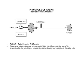

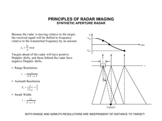
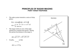
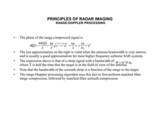
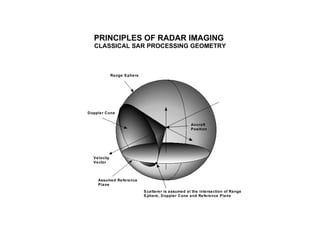
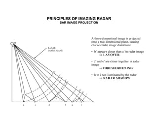
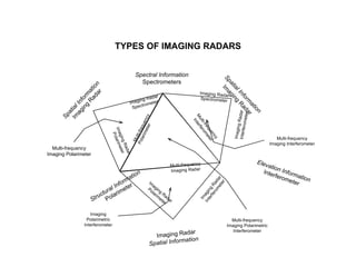
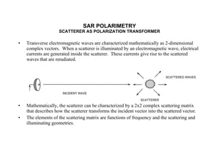
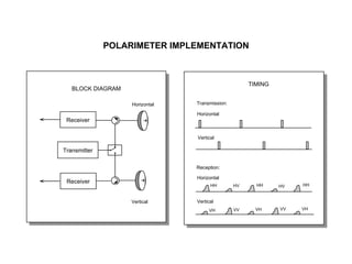
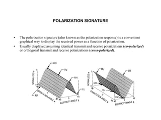
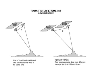
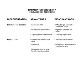
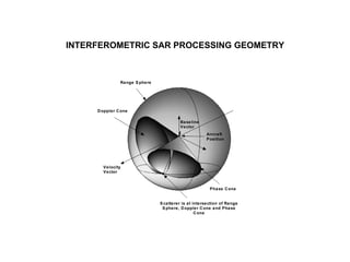
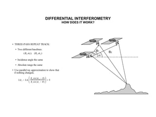
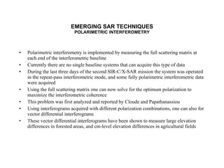

The document discusses principles of radar imaging and synthetic aperture radar (SAR). SAR uses signal modulation and range-Doppler processing to achieve high-resolution radar imagery independent of distance to targets. Polarimetric SAR can characterize target scattering properties by measuring the scattering matrix. Interferometric SAR uses two antennas to measure elevation, while differential interferometry detects elevation changes over time for applications like change detection. Emerging techniques include polarimetric interferometry and using polarization signatures to estimate surface tilt and topography.