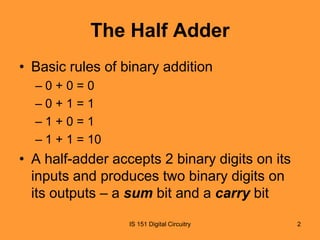
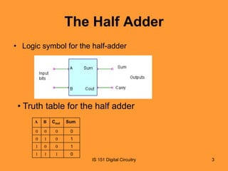
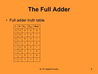
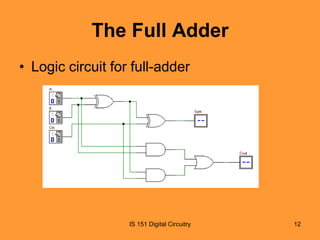
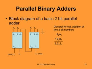
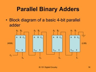
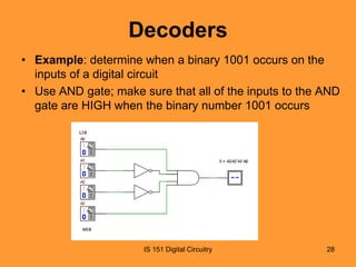
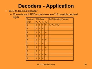
Functions of Combinational
Logic
• Basic Adders
– Important in computers and many types of
digital systems to process numerical data
– Basic adder operations are fundamental to
the study of digital systems

IS 151 Digital Circuitry

1
The Half Adder
• Basic rules of binary addition
–0+0=0
–0+1=1
–1+0=1
– 1 + 1 = 10

• A half-adder accepts 2 binary digits on its
inputs and produces two binary digits on
its outputs – a sum bit and a carry bit
IS 151 Digital Circuitry

2
The Half Adder
• Logic symbol for the half-adder

• Truth table for the half adder
A

B

Cout

Sum

0

0

0

0

0

1

0

1

1

0

0

1

1

1

1

0
IS 151 Digital Circuitry

3
The Half Adder
• Derive expressions for the Sum and Cout
as functions of inputs A and B
• From the truth table:
– Cout is a 1 only when both A and B are 1s:
Cout = AB
– Sum is a 1 only if A and B are not equal:
Sum = A B

IS 151 Digital Circuitry

4
The Half Adder
• Half-adder logic diagram

IS 151 Digital Circuitry

5
The Full Adder
• Accepts 3 inputs including an input carry
and generates a sum output and an
output carry
• Difference between half and full-adder
– the full adder has three inputs (including an
input carry) while a half adder has only two
inputs (without the input carry)

IS 151 Digital Circuitry

6
The Full Adder
Logic symbol for a full adder

IS 151 Digital Circuitry

7
The Full Adder
• Full adder truth table
A

B

Cin

Cout

Sum

0

0

0

0

0

0

0

1

0

1

0

1

0

0

1

0

1

1

1

0

1

0

0

0

1

1

0

1

1

0

1

1

0

1

0

1

1

1

1

1

IS 151 Digital Circuitry

8
The Full Adder
• Derive expressions for the Sum and Cout
as functions of inputs A, B and Cin from the
truth table
• Alternatively, using knowledge from the
half adder:
– Sum = inputs exclusively-ORed
• Sum = (A

B) Cin

– Cout = inputs ANDed
• AB + (A B)Cin
IS 151 Digital Circuitry

9
The Full Adder
• From the truth table:
– Sum = A’B’C + A’BC’+ AB’C’ + ABC
–
= A’B’C + ABC + A’BC’ + AB’C’
–
= C(A’B’ + AB) + C’(A’B + AB’)
–
= C(AexB)’ + C’(AexB)
–
= CexAexB
–
= AexBexC

IS 151 Digital Circuitry

10
The Full Adder
• Also from the truth table:
– Carry out = A’BC + AB’C ABC’ + ABC
–
= C(A’B + AB’) + AB(C’ + C)
–
= C(AexB) + AB
–
= AB + (AexB)C

IS 151 Digital Circuitry

11
The Full Adder
• Logic circuit for full-adder

IS 151 Digital Circuitry

12
The Full Adder - Exercise
• Determine an alternative method for
implementing the full-adder
– Write SoP expressions from the truth table for
Sum and Cout
– Map the expressions on K-maps and write
simplified expressions if any
– Implement/draw the circuit diagram for the
full-adder

IS 151 Digital Circuitry

13
Parallel Binary Adders
• A single full adder is capable of adding two 1- bit
numbers and an input carry
• To add binary numbers with more than one bit,
additional full-adders must be used.
• Example, for a 2-bit number, 2 full adders are
used, 4-bit numbers, 4 full-adders are used, etc.
• The carry output of each adder is connected to
the carry input of the next higher-order adder

IS 151 Digital Circuitry

14
Parallel Binary Adders
• Block diagram of a basic 2-bit parallel
adder
General format, addition of
two 2-bit numbers

A2

B2

A1

B1

A

B Cin

A

B Cin

A2A1
+ B2B1
Σ3Σ2Σ1

Cout

(MSB) Σ3

Σ

Σ2

Cout

Σ

Σ1 (LSB)

IS 151 Digital Circuitry

15
Parallel Binary Adders
• Block diagram of a basic 4-bit parallel
adder
A4

B4

A3

B3

A2

B2

A1

B1

A

B Cin

A

B Cin

A

B Cin

A

B Cin

(MSB)

(LSB)

Cout

Σ

Cout

Σ

Cout

Σ

Cout

Σ

C4

Σ4

Σ3

IS 151 Digital Circuitry

Σ2

Σ1

16
Comparators
• Basic function – to compare the magnitudes
of two binary quantities to determine the
relationship of those quantities
• Comparators determine whether two
numbers are equal or not

IS 151 Digital Circuitry

17
Comparators
• Basic comparator operations
The input bits are equal

The input bits are not equal

The input bits are equal

IS 151 Digital Circuitry

18
Comparators
• To compare binary numbers containing 2
bits each, an additional Ex-OR gate is
required

IS 151 Digital Circuitry

19
Comparators
• The two LSBs of the two numbers are compared
by gate G1, and the MSBs are compared by gate
G2
– Binary number A = A1A0
– Binary number B = B1B0

• If the two numbers are equal, their
corresponding bits are the same, and the output
of each Ex-OR gate is a 0
• The 0s are inverted using the inverter, producing
1s
• The 1s are ANDed, producing a 1, which
indicates equality
IS 151 Digital Circuitry

20
Comparators
• If the corresponding sets of bits are not equal,
i.e. A0≠B0, or A1≠B1, a 1 occurs on that Ex-OR
gate output (G1 or G2)
• In order to produce a single output indicating an
equality or inequality of two numbers, two
inverters and an AND gate are used
• When the two inputs are not equal, a 1,0 or 0,1
appears on the inputs of the AND gate,
producing a 0, indicating inequality
IS 151 Digital Circuitry

21
Comparators - Examples
• Determine whether A and B are equal (or
not) by following the logic levels through
the circuit
– a) A0 = 1, B0 = 0 and A1 = 1, B1 = 0
– b) A0 = 1, B0 = 1 and A1 = 1, B1 = 0

IS 151 Digital Circuitry

22
4-bit Comparators
• To determine if two numbers are equal
• If not, determine which one is greater or
less than the other
• Numbers
– A = A3A2A1A0
– B = B3B2B1B0

IS 151 Digital Circuitry

23
4-bit Comparators
• Determine the inequality by examining
highest-order bit in each other
– If A3 = 1 and B3 = 0; A > B
– If A3 = 0 and B3 = 1; A < B
– If A3 = B3, examine the next lower bit position
for an inequality (i.e. A2 with B2)

IS 151 Digital Circuitry

24
4-bit Comparators
• The three observations are valid for each
bit position in the numbers
• Check for an inequality in a bit position,
starting with the highest order bits
• When such an inequality is found, the
relationship of the two numbers is
established, and any other inequalities in
lower-order bit positions are ignored
IS 151 Digital Circuitry

25
Comparators - Example
• Implement a circuit to compare the relationship
between A and B
A

B

A>B

A=B

A<B

0

0

0

1

0

0

1

0

0

1

1

0

1

0

0

1

1

0

1

For A > B (G): G = AB’
For A = B (E): E = A’B’ + AB
For A < B (L): L = A’B

0

IS 151 Digital Circuitry

26
Decoders
• Function – to detect the presence of a
specified combination of bits (code) on
inputs and to indicate the presence of that
code by a specified output level
• n-input lines (to handle n bits)
• 1 to 2n output lines to indicate the
presence of 1 or more n-bit combinations

IS 151 Digital Circuitry

27
Decoders
• Example: determine when a binary 1001 occurs on the
inputs of a digital circuit
• Use AND gate; make sure that all of the inputs to the AND
gate are HIGH when the binary number 1001 occurs

IS 151 Digital Circuitry

28
Decoders
• Exercise: develop the logic required to
detect the binary code 10010 and produce
an active-LOW output (0)

IS 151 Digital Circuitry

29
Decoders - Application
• BCD-to-Decimal decoder
– Converts each BCD code into one of 10 possible decimal
digits
Decimal
Digit

BCD Code
A3 A2 A1 A0

BCD Decoding Function

0

0

0

0

0

A3’ A2’ A1’ A0’

1

0

0

0

1

2

0

0

1

0

3

0

0

1

1

4

0

1

0

0

5

0

1

0

1

6

0

1

1

0

7

0

1

1

1

8

1

0

0

0

9

1

0

0

1

IS 151 Digital Circuitry

30
Encoders
• A combinational logic circuit that performs
a reverse decoder function
• Accepts an active level on one of its inputs
(e.g. a decimal or octal digit) and converts
it to a coded output, e.g. BCD or binary

IS 151 Digital Circuitry

31
Encoders
• The Decimal-to-BCD Encoder (10-line-to-4-line encoder)
– Ten inputs (one for each decimal digit)
– Four outputs corresponding to the BCD code
• Logic symbol for a decimal-to-BCD encoder

Decimal
Input

DEC/BCD
0
1
2
3
1
4
2
5
4
6
8
7
8
9

BCD
Output

IS 151 Digital Circuitry

32
Encoders
• From the BCD/Decimal table, determine
the relationship between each BCD bit and
the decimal digits in order to analyse the
logic.
– Example
–
–
–
–

A3 = 8 + 9
A2 = 4 + 5 + 6 + 7
A1 = 2 + 3 + 6 + 7
A0 = 1 + 3 + 5 + 7 + 9

IS 151 Digital Circuitry

33
Encoders
• Example: if input line 9 is HIGH (assume
all others are LOW), it will produce a HIGH
on A3 and A0, and a LOW on A1and A2 –
which is 1001, meaning decimal 9.

IS 151 Digital Circuitry

34
Encoders - Exercise
• Implement the
logic circuit for the
10-line-to-4-line
encoder using the
logic expressions
for the BCD
codes A3 to A0
and inputs 0 to 9

IS 151 Digital Circuitry

35
Logic Functions Exercise
(Lab 3)
• Design and test a circuit to implement the
function of the full adder (refer to lecture)

IS 151 Digital Circuitry

36
• End of Lecture

IS 151 Digital Circuitry

37

IS 151 Lecture 9

  • 1.
    Functions of Combinational Logic •Basic Adders – Important in computers and many types of digital systems to process numerical data – Basic adder operations are fundamental to the study of digital systems IS 151 Digital Circuitry 1
  • 2.
    The Half Adder •Basic rules of binary addition –0+0=0 –0+1=1 –1+0=1 – 1 + 1 = 10 • A half-adder accepts 2 binary digits on its inputs and produces two binary digits on its outputs – a sum bit and a carry bit IS 151 Digital Circuitry 2
  • 3.
    The Half Adder •Logic symbol for the half-adder • Truth table for the half adder A B Cout Sum 0 0 0 0 0 1 0 1 1 0 0 1 1 1 1 0 IS 151 Digital Circuitry 3
  • 4.
    The Half Adder •Derive expressions for the Sum and Cout as functions of inputs A and B • From the truth table: – Cout is a 1 only when both A and B are 1s: Cout = AB – Sum is a 1 only if A and B are not equal: Sum = A B IS 151 Digital Circuitry 4
  • 5.
    The Half Adder •Half-adder logic diagram IS 151 Digital Circuitry 5
  • 6.
    The Full Adder •Accepts 3 inputs including an input carry and generates a sum output and an output carry • Difference between half and full-adder – the full adder has three inputs (including an input carry) while a half adder has only two inputs (without the input carry) IS 151 Digital Circuitry 6
  • 7.
    The Full Adder Logicsymbol for a full adder IS 151 Digital Circuitry 7
  • 8.
    The Full Adder •Full adder truth table A B Cin Cout Sum 0 0 0 0 0 0 0 1 0 1 0 1 0 0 1 0 1 1 1 0 1 0 0 0 1 1 0 1 1 0 1 1 0 1 0 1 1 1 1 1 IS 151 Digital Circuitry 8
  • 9.
    The Full Adder •Derive expressions for the Sum and Cout as functions of inputs A, B and Cin from the truth table • Alternatively, using knowledge from the half adder: – Sum = inputs exclusively-ORed • Sum = (A B) Cin – Cout = inputs ANDed • AB + (A B)Cin IS 151 Digital Circuitry 9
  • 10.
    The Full Adder •From the truth table: – Sum = A’B’C + A’BC’+ AB’C’ + ABC – = A’B’C + ABC + A’BC’ + AB’C’ – = C(A’B’ + AB) + C’(A’B + AB’) – = C(AexB)’ + C’(AexB) – = CexAexB – = AexBexC IS 151 Digital Circuitry 10
  • 11.
    The Full Adder •Also from the truth table: – Carry out = A’BC + AB’C ABC’ + ABC – = C(A’B + AB’) + AB(C’ + C) – = C(AexB) + AB – = AB + (AexB)C IS 151 Digital Circuitry 11
  • 12.
    The Full Adder •Logic circuit for full-adder IS 151 Digital Circuitry 12
  • 13.
    The Full Adder- Exercise • Determine an alternative method for implementing the full-adder – Write SoP expressions from the truth table for Sum and Cout – Map the expressions on K-maps and write simplified expressions if any – Implement/draw the circuit diagram for the full-adder IS 151 Digital Circuitry 13
  • 14.
    Parallel Binary Adders •A single full adder is capable of adding two 1- bit numbers and an input carry • To add binary numbers with more than one bit, additional full-adders must be used. • Example, for a 2-bit number, 2 full adders are used, 4-bit numbers, 4 full-adders are used, etc. • The carry output of each adder is connected to the carry input of the next higher-order adder IS 151 Digital Circuitry 14
  • 15.
    Parallel Binary Adders •Block diagram of a basic 2-bit parallel adder General format, addition of two 2-bit numbers A2 B2 A1 B1 A B Cin A B Cin A2A1 + B2B1 Σ3Σ2Σ1 Cout (MSB) Σ3 Σ Σ2 Cout Σ Σ1 (LSB) IS 151 Digital Circuitry 15
  • 16.
    Parallel Binary Adders •Block diagram of a basic 4-bit parallel adder A4 B4 A3 B3 A2 B2 A1 B1 A B Cin A B Cin A B Cin A B Cin (MSB) (LSB) Cout Σ Cout Σ Cout Σ Cout Σ C4 Σ4 Σ3 IS 151 Digital Circuitry Σ2 Σ1 16
  • 17.
    Comparators • Basic function– to compare the magnitudes of two binary quantities to determine the relationship of those quantities • Comparators determine whether two numbers are equal or not IS 151 Digital Circuitry 17
  • 18.
    Comparators • Basic comparatoroperations The input bits are equal The input bits are not equal The input bits are equal IS 151 Digital Circuitry 18
  • 19.
    Comparators • To comparebinary numbers containing 2 bits each, an additional Ex-OR gate is required IS 151 Digital Circuitry 19
  • 20.
    Comparators • The twoLSBs of the two numbers are compared by gate G1, and the MSBs are compared by gate G2 – Binary number A = A1A0 – Binary number B = B1B0 • If the two numbers are equal, their corresponding bits are the same, and the output of each Ex-OR gate is a 0 • The 0s are inverted using the inverter, producing 1s • The 1s are ANDed, producing a 1, which indicates equality IS 151 Digital Circuitry 20
  • 21.
    Comparators • If thecorresponding sets of bits are not equal, i.e. A0≠B0, or A1≠B1, a 1 occurs on that Ex-OR gate output (G1 or G2) • In order to produce a single output indicating an equality or inequality of two numbers, two inverters and an AND gate are used • When the two inputs are not equal, a 1,0 or 0,1 appears on the inputs of the AND gate, producing a 0, indicating inequality IS 151 Digital Circuitry 21
  • 22.
    Comparators - Examples •Determine whether A and B are equal (or not) by following the logic levels through the circuit – a) A0 = 1, B0 = 0 and A1 = 1, B1 = 0 – b) A0 = 1, B0 = 1 and A1 = 1, B1 = 0 IS 151 Digital Circuitry 22
  • 23.
    4-bit Comparators • Todetermine if two numbers are equal • If not, determine which one is greater or less than the other • Numbers – A = A3A2A1A0 – B = B3B2B1B0 IS 151 Digital Circuitry 23
  • 24.
    4-bit Comparators • Determinethe inequality by examining highest-order bit in each other – If A3 = 1 and B3 = 0; A > B – If A3 = 0 and B3 = 1; A < B – If A3 = B3, examine the next lower bit position for an inequality (i.e. A2 with B2) IS 151 Digital Circuitry 24
  • 25.
    4-bit Comparators • Thethree observations are valid for each bit position in the numbers • Check for an inequality in a bit position, starting with the highest order bits • When such an inequality is found, the relationship of the two numbers is established, and any other inequalities in lower-order bit positions are ignored IS 151 Digital Circuitry 25
  • 26.
    Comparators - Example •Implement a circuit to compare the relationship between A and B A B A>B A=B A<B 0 0 0 1 0 0 1 0 0 1 1 0 1 0 0 1 1 0 1 For A > B (G): G = AB’ For A = B (E): E = A’B’ + AB For A < B (L): L = A’B 0 IS 151 Digital Circuitry 26
  • 27.
    Decoders • Function –to detect the presence of a specified combination of bits (code) on inputs and to indicate the presence of that code by a specified output level • n-input lines (to handle n bits) • 1 to 2n output lines to indicate the presence of 1 or more n-bit combinations IS 151 Digital Circuitry 27
  • 28.
    Decoders • Example: determinewhen a binary 1001 occurs on the inputs of a digital circuit • Use AND gate; make sure that all of the inputs to the AND gate are HIGH when the binary number 1001 occurs IS 151 Digital Circuitry 28
  • 29.
    Decoders • Exercise: developthe logic required to detect the binary code 10010 and produce an active-LOW output (0) IS 151 Digital Circuitry 29
  • 30.
    Decoders - Application •BCD-to-Decimal decoder – Converts each BCD code into one of 10 possible decimal digits Decimal Digit BCD Code A3 A2 A1 A0 BCD Decoding Function 0 0 0 0 0 A3’ A2’ A1’ A0’ 1 0 0 0 1 2 0 0 1 0 3 0 0 1 1 4 0 1 0 0 5 0 1 0 1 6 0 1 1 0 7 0 1 1 1 8 1 0 0 0 9 1 0 0 1 IS 151 Digital Circuitry 30
  • 31.
    Encoders • A combinationallogic circuit that performs a reverse decoder function • Accepts an active level on one of its inputs (e.g. a decimal or octal digit) and converts it to a coded output, e.g. BCD or binary IS 151 Digital Circuitry 31
  • 32.
    Encoders • The Decimal-to-BCDEncoder (10-line-to-4-line encoder) – Ten inputs (one for each decimal digit) – Four outputs corresponding to the BCD code • Logic symbol for a decimal-to-BCD encoder Decimal Input DEC/BCD 0 1 2 3 1 4 2 5 4 6 8 7 8 9 BCD Output IS 151 Digital Circuitry 32
  • 33.
    Encoders • From theBCD/Decimal table, determine the relationship between each BCD bit and the decimal digits in order to analyse the logic. – Example – – – – A3 = 8 + 9 A2 = 4 + 5 + 6 + 7 A1 = 2 + 3 + 6 + 7 A0 = 1 + 3 + 5 + 7 + 9 IS 151 Digital Circuitry 33
  • 34.
    Encoders • Example: ifinput line 9 is HIGH (assume all others are LOW), it will produce a HIGH on A3 and A0, and a LOW on A1and A2 – which is 1001, meaning decimal 9. IS 151 Digital Circuitry 34
  • 35.
    Encoders - Exercise •Implement the logic circuit for the 10-line-to-4-line encoder using the logic expressions for the BCD codes A3 to A0 and inputs 0 to 9 IS 151 Digital Circuitry 35
  • 36.
    Logic Functions Exercise (Lab3) • Design and test a circuit to implement the function of the full adder (refer to lecture) IS 151 Digital Circuitry 36
  • 37.
    • End ofLecture IS 151 Digital Circuitry 37