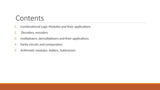
Contents
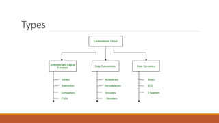
1. Combinational LogicModules and their applications
2. Decoders, encoders
3. multiplexers, demultiplexers and their applications
4. Parity circuits and comparators
5. Arithmetic modules- Adders, Subtractors
3.
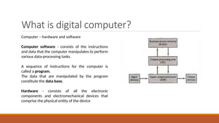
What is digitalcomputer?
Computer – hardware and software
Computer software - consists of the instructions
and data that the computer manipulates to perform
various data-processing tasks.
A sequence of instructions for the computer is
called a program.
The data that are manipulated by the program
constitute the data base.
Hardware - consists of all the electronic
components and electromechanical devices that
comprise the physical entity of the device
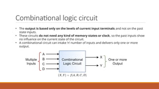
Combinational logic circuit
•The output is based only on the levels of current input terminals and not on the past
state inputs.
• These circuits do not need any kind of memory states or clock, so the past inputs show
no influence on the current state of the circuit.
• A combinational circuit can intake ‘n’ number of inputs and delivers only one or more
output.
9.
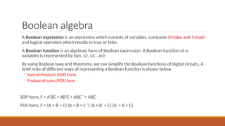
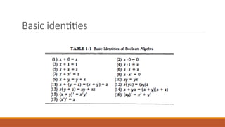
Boolean algebra
A Booleanexpression is an expression which consists of variables, constants (0-false and 1-true)
and logical operators which results in true or false.
A Boolean function is an algebraic form of Boolean expression. A Boolean function of n-
variables is represented by f(x1, x2, x3….xn).
By using Boolean laws and theorems, we can simplify the Boolean functions of digital circuits. A
brief note of different ways of representing a Boolean function is shown below.
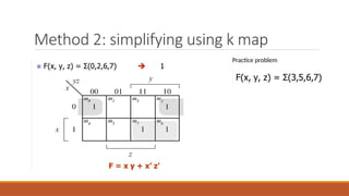
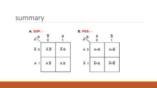
◦ Sum-of-Products (SOP) Form
◦ Product-of-sums (POS) form
SOP form, F = A’BC + AB’C + ABC ‘ + ABC
POS form, F = (A + B + C) (A + B + C ‘) (A + B’ + C) (A’ + B + C)
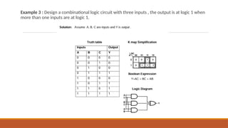
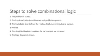
Steps to solvecombinational logic
1. The problem is stated.
2. The input and output variables are assigned letter symbols.
3. The truth table that defines the relationship between inputs and outputs
is derived.
4. The simplified Boolean functions for each output are obtained.
5. The logic diagram is drawn.
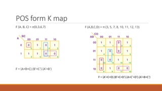
POS form Kmap
F (A, B, C) = π(0,3,6,7)
F = (A+B+C).(B’+C’).(A’+B’)
F (A,B,C,D) = π (3, 5, 7, 8, 10, 11, 12, 13)
F = (A’+C+D).(B’+C+D’).(A+C’+D’).(A’+B+C’)
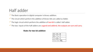
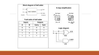
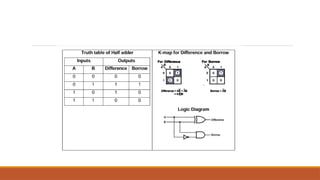
Half adder
TheBasic operation in digital computer is binary addition.
The circuit which perform the addition of binary bits are called as Adder.
The logic circuit which perform the addition of two bit is called Half adder.
The two inputs of the half adders are augend and addend, the outputs are sum and carry.
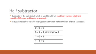
Half subtractor
Subtractoris the logic circuit which is used to subtract two binary number (digit) and
provides Difference and Borrow as a output.
In digital electronics we have two types of subtractor, Half Subtractor and Full Subtractor.
30.
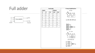
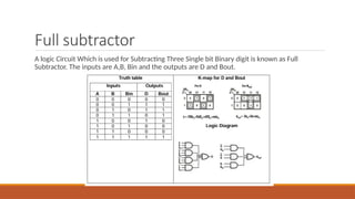
Full subtractor
A logicCircuit Which is used for Subtracting Three Single bit Binary digit is known as Full
Subtractor. The inputs are A,B, Bin and the outputs are D and Bout.
32.
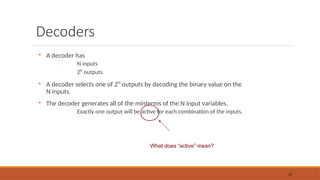
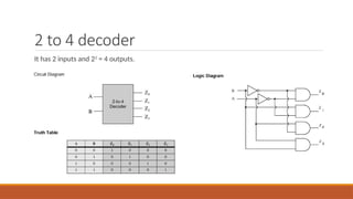
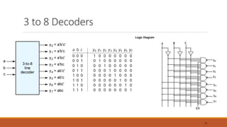
Decoders
A decoder has
N inputs
2N
outputs
A decoder selects one of 2N
outputs by decoding the binary value on the
N inputs.
The decoder generates all of the minterms of the N input variables.
Exactly one output will be active for each combination of the inputs.
32
What does “active” mean?
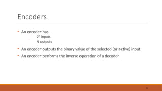
Encoders
An encoder has
2N
inputs
N outputs
An encoder outputs the binary value of the selected (or active) input.
An encoder performs the inverse operation of a decoder.
38
39.
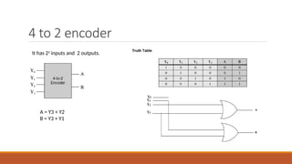
4 to 2encoder
A = Y3 + Y2
B = Y3 + Y1
It has 22
inputs and 2 outputs.
40.
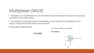
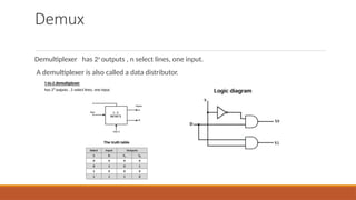
Multiplexer (MUX)
Multiplexeris a combinational circuit that selects binary information from one of many inputs
and directs it into single output.
The selection of particular input is controlled by a set of selection line Mutliplexer has 2n
inputs, n select line (control input) and one output
It also called as Data selector
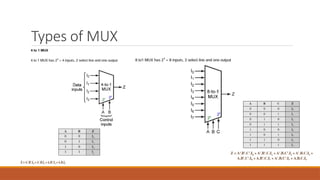
2 to 1 MUX
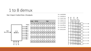
1 to 8demux
Has 1 input; 3-select lines ; 8-outputs
47.
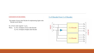
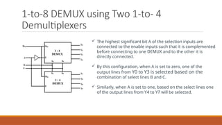
1-to-8 DEMUX usingTwo 1-to- 4
Demultiplexers
The highest significant bit A of the selection inputs are
connected to the enable inputs such that it is complemented
before connecting to one DEMUX and to the other it is
directly connected.
By this configuration, when A is set to zero, one of the
output lines from Y0 to Y3 is selected based on the
combination of select lines B and C.
Similarly, when A is set to one, based on the select lines one
of the output lines from Y4 to Y7 will be selected.
48.
Parity generator andcircuits
Parity bit- is a basic way to check for errors in digital communications and data storage, used to
make sure data stays accurate. It’s an extra binary digit added to a string of binary code.
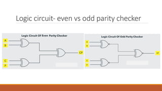
Even Parity:
The parity bit is adjusted so that the total number of 1s in the code, including the parity bit, is
even. If there are already an even number of 1s, the parity bit is 0. If there are an odd number of
1s, the parity bit is 1.
Odd Parity:
The parity bit is adjusted to make the total number of 1s odd. If there are already an odd
number of 1s, the parity bit is 0. If it’s even, the parity bit is set to 1. Such error detecting and
correction can be implemented by using Ex-OR gates (since Ex-OR gate produce zero output
when there are even number of inputs).
49.
Parity generator
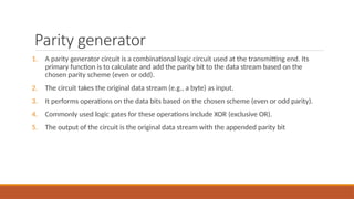
1. Aparity generator circuit is a combinational logic circuit used at the transmitting end. Its
primary function is to calculate and add the parity bit to the data stream based on the
chosen parity scheme (even or odd).
2. The circuit takes the original data stream (e.g., a byte) as input.
3. It performs operations on the data bits based on the chosen scheme (even or odd parity).
4. Commonly used logic gates for these operations include XOR (exclusive OR).
5. The output of the circuit is the original data stream with the appended parity bit
50.
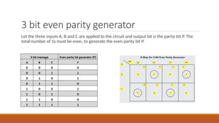
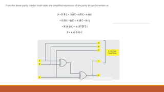
3 bit evenparity generator
Let the three inputs A, B and C are applied to the circuit and output bit is the parity bit P. The
total number of 1s must be even, to generate the even parity bit P.
52.
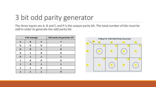
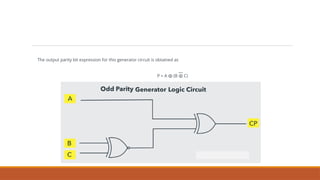
3 bit oddparity generator
The three inputs are A, B and C and P is the output parity bit. The total number of bits must be
odd in order to generate the odd parity bit.
54.
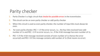
Parity checker
1. ParityChecker is a logic circuit that checks for possible errors in the transmission.
2. This circuit can be an even parity checker or odd parity checker
3. When this circuit is used as even parity checker, the number of input bits must always be
even.
4. for even parity checker, PEC = 1 if the error occurs, i.e., the four bits received have odd
number of 1s and PEC = 0 if no error occurs, i.e., if the 4-bit message has even number of 1s.
5. PEC =1 if the 4-bit message received consists of even number of 1s (hence the error
occurred) and PEC= 0 if the message contains odd number of 1s (that means no error).
55.
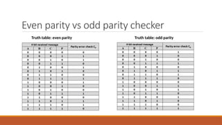
Even parity vsodd parity checker
Truth table: even parity Truth table: odd parity
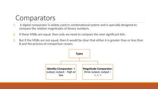
Comparators
1. A digitalcomparator is widely used in combinational system and is specially designed to
compare the relative magnitudes of binary numbers.
2. If these MSBs are equal, then only we need to compare the next significant bits.
3. But if the MSBs are not equal, then it would be clear that either A is greater than or less than
B and the process of comparison ceases.
Types
Identity Comparator- 1
output; output – high or
low
Magnitude Comparator-
three output; output –
>, <, =
59.
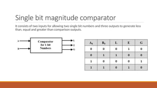
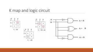
Single bit magnitudecomparator
It consists of two inputs for allowing two single bit numbers and three outputs to generate less
than, equal and greater than comparison outputs.
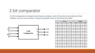
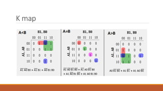
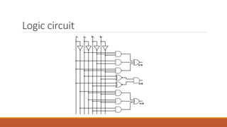
2 bit comparator
A2-bit comparator compares two binary numbers, each of two bits and produces their
relation such as one number is equal or greater than or less than the other.

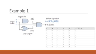
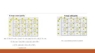
![Sop form
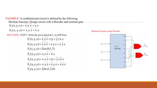
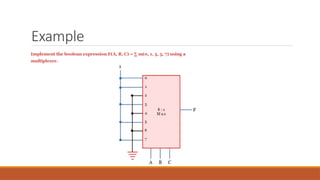
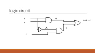
Find simplified Boolean expression and draw the logic circuit
Y=A’BC+AB’C+AB(C+C’)
Y=A’BC+AB’C+AB [SINCE C+C’=1]](https://image.slidesharecdn.com/module1-digitalelectronics-250507080440-bd24d311/85/Module-1-basics-of-Digital-Electronics-pptx-16-320.jpg)