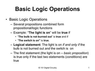
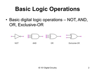
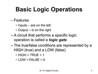
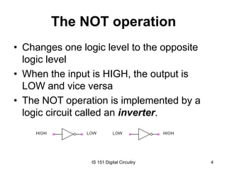
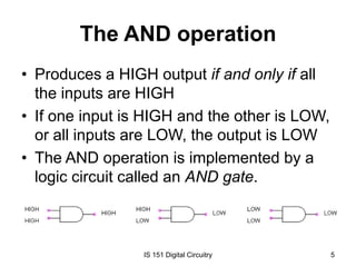
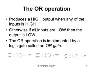
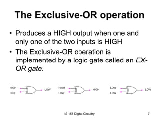
Basic Logic Operations
• Basic Logic Operations
– Several propositions combined form
propositional/logic functions
– Example: “The light is on” will be true if
• “The bulb is not burned out” is true and if
• “The switch is on” is true.

– Logical statement: The light is on if and only if the
bulb is not burned out and the switch is on
– The first statement (the light is on – basic proposition)
is true only if the last two statements (conditions) are
true
IS 151 Digital Circuitry

1
Basic Logic Operations
• Basic digital logic operations – NOT, AND,
OR, Exclusive-OR

IS 151 Digital Circuitry

2
Basic Logic Operations
– Features
• Inputs – are on the left
• Output – is on the right

– A circuit that performs a specific logic
operation is called a logic gate
– The true/false conditions are represented by a
HIGH (true) and a LOW (false)
• HIGH = TRUE = 1
• LOW = FALSE = 0

IS 151 Digital Circuitry

3
The NOT operation
• Changes one logic level to the opposite
logic level
• When the input is HIGH, the output is
LOW and vice versa
• The NOT operation is implemented by a
logic circuit called an inverter.

IS 151 Digital Circuitry

4
The AND operation
• Produces a HIGH output if and only if all
the inputs are HIGH
• If one input is HIGH and the other is LOW,
or all inputs are LOW, the output is LOW
• The AND operation is implemented by a
logic circuit called an AND gate.

IS 151 Digital Circuitry

5
The OR operation
• Produces a HIGH output when any of the
inputs is HIGH
• Otherwise if all inputs are LOW then the
output is LOW
• The OR operation is implemented by a
logic gate called an OR gate.

IS 151 Digital Circuitry

6
The Exclusive-OR operation
• Produces a HIGH output when one and
only one of the two inputs is HIGH
• The Exclusive-OR operation is
implemented by a logic gate called an EXOR gate.

IS 151 Digital Circuitry

7
Logic Operations - Review
1. When does the NOT operation produce a HIGH/LOW
output?
2. When does the AND operation produce a HIGH/LOW
output?
3. When does the OR operation produce a HIGH/LOW
output?
4. When does the EX-OR operation produce a HIGH/LOW
output?
5. What is an inverter?
6. What is a logic gate?
7. What is the difference between an OR and an
Exclusive-OR operation?
IS 151 Digital Circuitry

8
Basic Logic Functions
• The basic logic gates can be combined to
form more complex logic circuits that
perform many useful operations to build up
complete digital systems
• Some common logic functions:
comparison, arithmetic, code conversion,
encoding, decoding, data selection,
storage, and counting
IS 151 Digital Circuitry

9
The Comparison Function
• Magnitude comparison is performed by a
logic circuit called the comparator.
• A comparator compares two quantities and
indicates whether or not they are equal.
• Example: given two numbers, determine if
the numbers are equal, and if not equal,
which one is greater.

IS 151 Digital Circuitry

10
Arithmetic Functions
• Addition – performed by an adder; adds two
binary numbers (two inputs and a carry in) and
generates an output and a carry out
• Subtraction – performed by a subtracter; three
inputs: two numbers and a borrow input;
generates the difference and borrow out
• Multiplication – performed by a multiplier; have
two inputs, and an output (product)
• Division – performed by a series of
subtractions, comparisons and shifts; have two
inputs and two outputs (quotient and reminder)
IS 151 Digital Circuitry

11
Code Functions
• The Code conversion function
– Changes a form of coded information into
another coded form

• The Encoding function
– Converts information into some coded form

• The Decoding function
– Converts coded information into a
nonencoded form
IS 151 Digital Circuitry

12
The Data Selection Functions
• Multiplexer – switches digital data from
several input lines onto a single output line
in a specified time sequence
• Demultiplexer – switches digital data from
one input line to several output lines in a
specified time sequence

IS 151 Digital Circuitry

13
Storage and Counting Functions
• The Storage function
– To retain binary data for a period of time; e.g.
flip-flops, registers

• The Counting function
– To count events represented by changing
levels or pulses or to generate particular code
sequence.

IS 151 Digital Circuitry

14
• End of Lecture

IS 151 Digital Circuitry

15

IS 151 - Lecture 3

  • 1.
    Basic Logic Operations •Basic Logic Operations – Several propositions combined form propositional/logic functions – Example: “The light is on” will be true if • “The bulb is not burned out” is true and if • “The switch is on” is true. – Logical statement: The light is on if and only if the bulb is not burned out and the switch is on – The first statement (the light is on – basic proposition) is true only if the last two statements (conditions) are true IS 151 Digital Circuitry 1
  • 2.
    Basic Logic Operations •Basic digital logic operations – NOT, AND, OR, Exclusive-OR IS 151 Digital Circuitry 2
  • 3.
    Basic Logic Operations –Features • Inputs – are on the left • Output – is on the right – A circuit that performs a specific logic operation is called a logic gate – The true/false conditions are represented by a HIGH (true) and a LOW (false) • HIGH = TRUE = 1 • LOW = FALSE = 0 IS 151 Digital Circuitry 3
  • 4.
    The NOT operation •Changes one logic level to the opposite logic level • When the input is HIGH, the output is LOW and vice versa • The NOT operation is implemented by a logic circuit called an inverter. IS 151 Digital Circuitry 4
  • 5.
    The AND operation •Produces a HIGH output if and only if all the inputs are HIGH • If one input is HIGH and the other is LOW, or all inputs are LOW, the output is LOW • The AND operation is implemented by a logic circuit called an AND gate. IS 151 Digital Circuitry 5
  • 6.
    The OR operation •Produces a HIGH output when any of the inputs is HIGH • Otherwise if all inputs are LOW then the output is LOW • The OR operation is implemented by a logic gate called an OR gate. IS 151 Digital Circuitry 6
  • 7.
    The Exclusive-OR operation •Produces a HIGH output when one and only one of the two inputs is HIGH • The Exclusive-OR operation is implemented by a logic gate called an EXOR gate. IS 151 Digital Circuitry 7
  • 8.
    Logic Operations -Review 1. When does the NOT operation produce a HIGH/LOW output? 2. When does the AND operation produce a HIGH/LOW output? 3. When does the OR operation produce a HIGH/LOW output? 4. When does the EX-OR operation produce a HIGH/LOW output? 5. What is an inverter? 6. What is a logic gate? 7. What is the difference between an OR and an Exclusive-OR operation? IS 151 Digital Circuitry 8
  • 9.
    Basic Logic Functions •The basic logic gates can be combined to form more complex logic circuits that perform many useful operations to build up complete digital systems • Some common logic functions: comparison, arithmetic, code conversion, encoding, decoding, data selection, storage, and counting IS 151 Digital Circuitry 9
  • 10.
    The Comparison Function •Magnitude comparison is performed by a logic circuit called the comparator. • A comparator compares two quantities and indicates whether or not they are equal. • Example: given two numbers, determine if the numbers are equal, and if not equal, which one is greater. IS 151 Digital Circuitry 10
  • 11.
    Arithmetic Functions • Addition– performed by an adder; adds two binary numbers (two inputs and a carry in) and generates an output and a carry out • Subtraction – performed by a subtracter; three inputs: two numbers and a borrow input; generates the difference and borrow out • Multiplication – performed by a multiplier; have two inputs, and an output (product) • Division – performed by a series of subtractions, comparisons and shifts; have two inputs and two outputs (quotient and reminder) IS 151 Digital Circuitry 11
  • 12.
    Code Functions • TheCode conversion function – Changes a form of coded information into another coded form • The Encoding function – Converts information into some coded form • The Decoding function – Converts coded information into a nonencoded form IS 151 Digital Circuitry 12
  • 13.
    The Data SelectionFunctions • Multiplexer – switches digital data from several input lines onto a single output line in a specified time sequence • Demultiplexer – switches digital data from one input line to several output lines in a specified time sequence IS 151 Digital Circuitry 13
  • 14.
    Storage and CountingFunctions • The Storage function – To retain binary data for a period of time; e.g. flip-flops, registers • The Counting function – To count events represented by changing levels or pulses or to generate particular code sequence. IS 151 Digital Circuitry 14
  • 15.
    • End ofLecture IS 151 Digital Circuitry 15