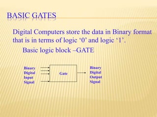
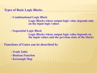
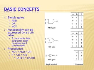
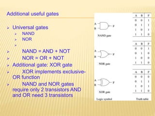
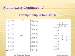
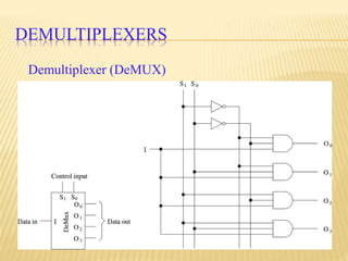
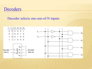
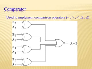
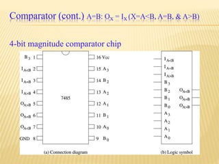
DIGITAL ELECTRONICS
RC1225_013
Nandhini V. L (Team Leader)
Kusuma M.S.
Digital Electronics is a branch of Electronics
deals with the digital circuits and digital
signals.
Basics
Combinational Circuits
Sequentional Circuits
BASIC GATES
Digital Computers store the data in Binary format
that is in terms of logic ‘0’ and logic ‘1’.
Basic logic block –GATE
Binary
Digital
Input
Signal
Binary
Digital
Output
Signal
Gate
Types of Basic Logic Blocks
- Combinational Logic Block
Logic Blocks whose output logic value depends only
on the input logic values
- Sequential Logic Block
Logic Blocks whose output logic value depends on
the input values and the previous state of the blocks
Functions of Gates can be described by
- Truth Table
- Boolean Function
- Karnaugh Map
BASIC CONCEPTS
 Simple gates
 AND
 OR
 NOT
 Functionality can be
expressed by a truth
table
 A truth table lists
output for each
possible input
combination
 Precedence
 NOT > AND > OR
 F = A B’ + A’ B
 = (A (B’)) + ((A’) B)
Additional useful gates
 Universal gates
 NAND
 NOR

 NAND = AND + NOT
 NOR = OR + NOT
 Additional gate: XOR gate
 XOR implements exclusive-
OR function
 NAND and NOR gates
require only 2 transistors AND
and OR need 3 transistors
COMBINATIONAL CIRCUITS
Output depends only on the present inputs.
Combinational circuits provide a higher level of
abstraction.
Help in reducing design complexity.
Reduce chip count.
We look at some useful combinational circuits
COMBINATIONAL LOGIC CIRCUITS
Half Adder
Full Adder
Multiplexer
Encoder
Decoder
Parity Checker
Parity Generator etc
ADDERS
Half-adder
Adds two bits
Produces a sum and carry
Full-adder
Adds three 1-bit values
Like half-adder, produces a sum and carry
Allows building N-bit adders
Simple technique
Connect Cout of one adder to Cin of the next
These are called ripple-carry adders
a sum
b carry
Cout
sum
Cin
a
b
HA
FA
MULTIPLEXER
 2n data inputs
 n selection inputs
 a single output
 Selection input determines the input that should be
connected to the output
Multiplexers(Continued…)
4-data input MUX implementation
Multiplexers(Continued…)
4-data input MUX
Multiplexers(Continued…)
Example chip: 8-to-1 MUX
Demultiplexer (DeMUX)
DEMULTIPLEXERS
Decoders
Decoder selects one-out-of-N inputs
Comparator
Used to implement comparison operators (= , > , < ,  , )
Comparator (cont.) A=B: OX = IX (X=A<B, A=B, & A>B)
4-bit magnitude comparator chip
Thank you

Digital electronics nandhini kusuma