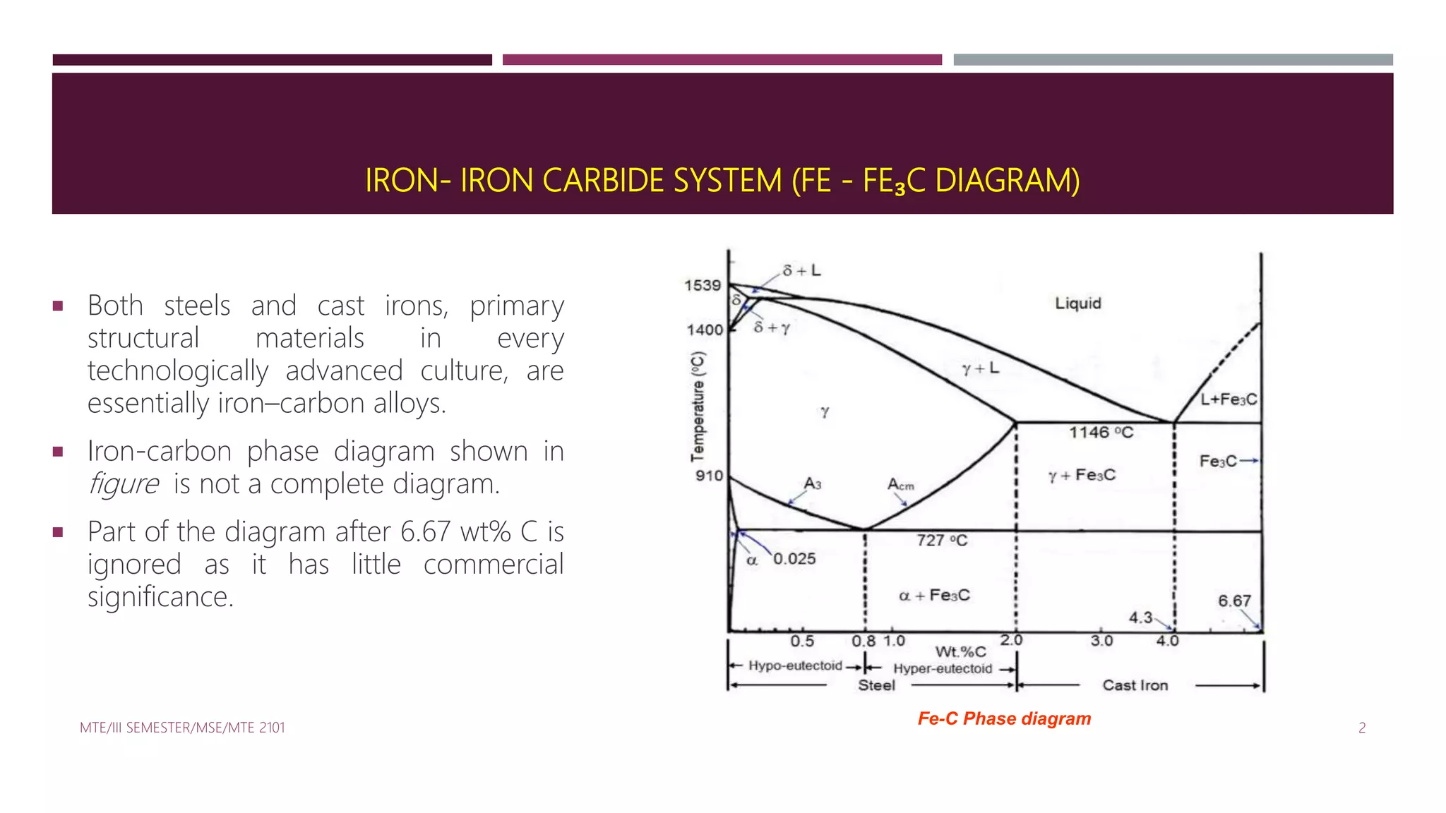
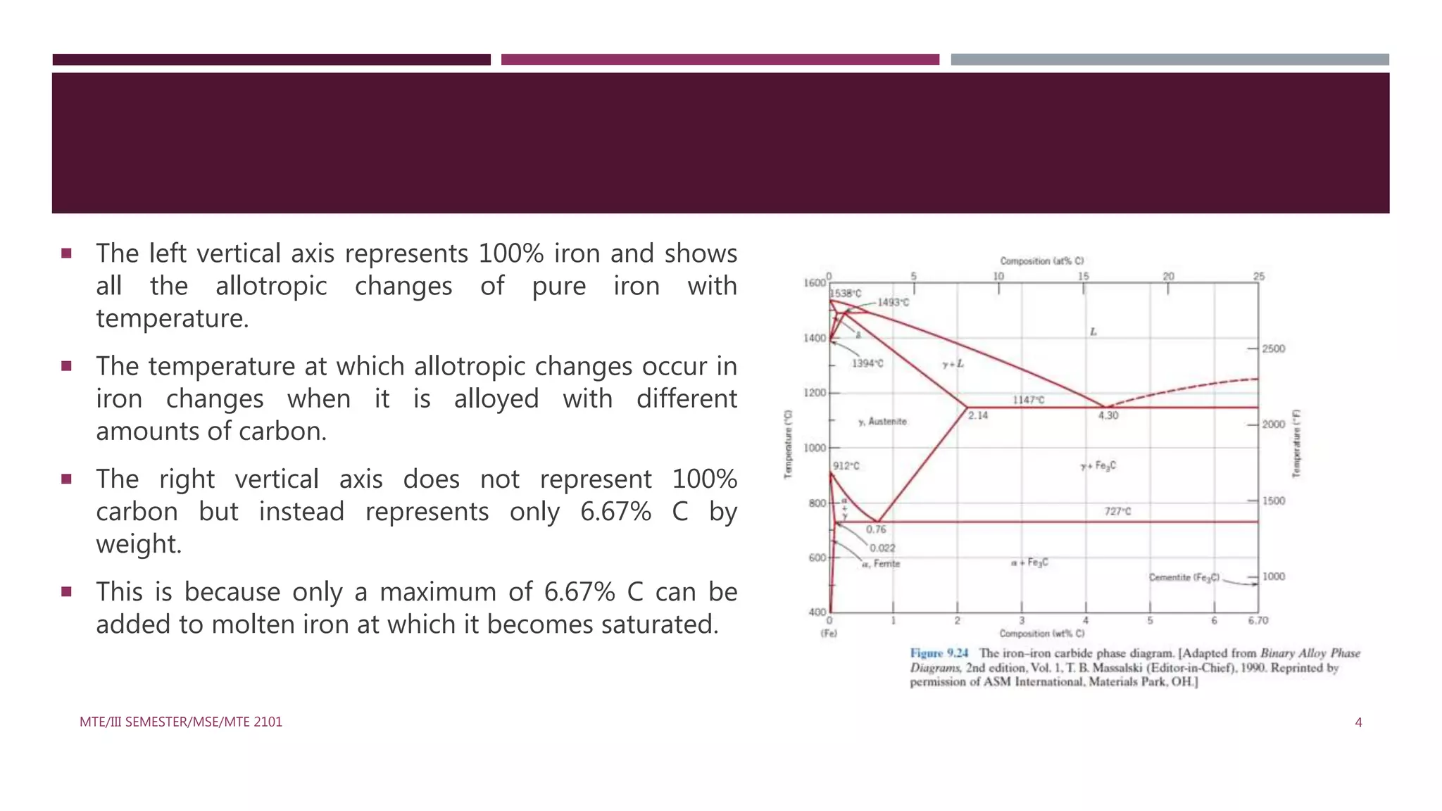
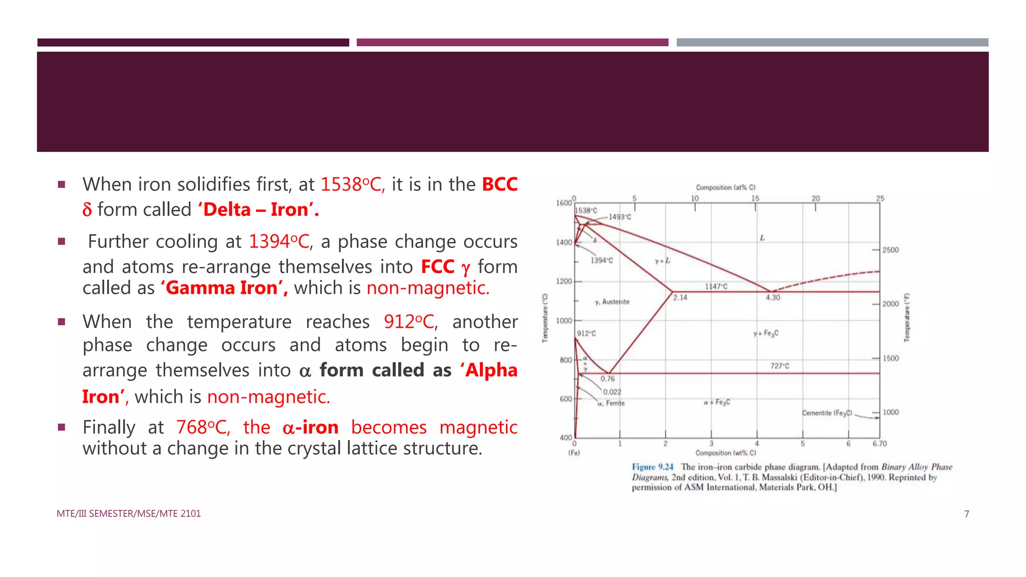
SlideShare a Scribd company logo
IRON-CARBON SYSTEM
IRON- IRON CARBIDE SYSTEM (FE - FE₃C DIAGRAM)
 Both steels and cast irons, primary
structural materials in every
technologically advanced culture, are
essentially iron–carbon alloys.
 Iron-carbon phase diagram shown in
figure is not a complete diagram.
 Part of the diagram after 6.67 wt% C is
ignored as it has little commercial
significance.
MTE/III SEMESTER/MSE/MTE 2101 2
Fe-C Phase diagram
MTE/III SEMESTER/MSE/MTE 2101 3
Pic Courtesy: Material Science and Engineering,
CallisterIron – Iron carbide phase diagram
 The left vertical axis represents 100% iron and shows
all the allotropic changes of pure iron with
temperature.
 The temperature at which allotropic changes occur in
iron changes when it is alloyed with different
amounts of carbon.
 The right vertical axis does not represent 100%
carbon but instead represents only 6.67% C by
weight.
 This is because only a maximum of 6.67% C can be
added to molten iron at which it becomes saturated.
MTE/III SEMESTER/MSE/MTE 2101 4
 Any further addition of carbon will not dissolve in iron but rather floats or gets blown away owing to its
very low density. Iron when contains exactly 6.67% C by weight forms an intermediate phase called
Cementite or Iron Carbide (Fe3C).
 Hence, the Iron-Carbon equilibrium diagram is actually called as the Iron – Iron Carbide Equilibrium
Diagram with pure iron and pure Fe3C (Iron Carbide) forming the extremities.
 Actually, the phase Fe3C (Iron Carbide) is called meta stable state because it decomposes with passage
of time.
 Here, the equilibrium phase diagram for iron and carbon assumes that Fe3C is stable with respect to
time. Hence, it is not a true equilibrium diagram.
MTE/III SEMESTER/MSE/MTE 2101 5
Characteristics of Fe-C Diagram
 The Fe-Fe₃C is characterized by five individual phases and three invariant reactions.
 Five phases that exist in the diagram are: α–ferrite (BCC) Fe-C solid solution, γ-austenite (FCC) Fe-C
solid solution, δ-ferrite (BCC) Fe-C solid solution, Fe₃C (iron carbide) or cementite - an inter-metallic
compound and liquid Fe-C solution.
 Three invariant reactions that cause transformations in the system are namely: eutectoid, eutectic, and
peritectic.
MTE/III SEMESTER/MSE/MTE 2101 6
 When iron solidifies first, at 1538oC, it is in the BCC
 form called ‘Delta – Iron’.
 Further cooling at 1394oC, a phase change occurs
and atoms re-arrange themselves into FCC  form
called as ‘Gamma Iron’, which is non-magnetic.
 When the temperature reaches 912oC, another
phase change occurs and atoms begin to re-
arrange themselves into  form called as ‘Alpha
Iron’, which is non-magnetic.
 Finally at 768oC, the -iron becomes magnetic
without a change in the crystal lattice structure.
MTE/III SEMESTER/MSE/MTE 2101 7
MTE/III SEMESTER/MSE/MTE 2101 8
Cooling Curves of Fe – C Diagram
The diagram shows 3 horizontal lines (isotherms)
which represent 3 invariant reactions:
(a) The first isotherm at 1493oC indicates the
peritectic reaction. This region where the peritectic
reaction takes place is called the Delta region.
(b) The second isotherm at 1147oC indicates the
eutectic reaction. This region where the eutectic
reaction takes place is called the Eutectic region.
(c) The third isotherm at 727oC indicates the
eutectoid reaction. This region where the eutectoid
reaction takes place is called the Eutectoid region.
MTE/III SEMESTER/MSE/MTE 2101 9
 Carbon is an interstitial impurity in iron and forms a solid solution with each of α and δ ferrites, and also
with austenite, as indicated by the α,γ and δ single phase fields.
α - Ferrite Phase (912ᵒC-768ᵒC):
 In the BCC α ferrite, only small concentrations of carbon are soluble; the maximum solubility is 0.022
wt% at 727°C.
 The interstitial position in BCC, α – Ferrite is very small to accommodate carbon atoms. It is because of
this reason the solubility is less .
 This particular iron–carbon phase is relatively soft, may be made magnetic at temperatures below 768°C
and has a density of 7.88 g/cm³.
MTE/III SEMESTER/MSE/MTE 2101 10
γ – Austenite Phase (1394ᵒC-912ᵒC):
 The austenite, or γ phase of iron, when alloyed with carbon alone, is not stable below 727°C.
 The maximum solubility of carbon in austenite, 2.14 wt%, occurs at 1147°C.
 This solubility is approximately 100 times greater than the maximum for BCC ferrite, since the FCC
interstitial positions are larger, and, therefore, the strains imposed on the surrounding iron atoms are
much lower.
 Austenite is nonmagnetic.
δ Phase (1538ᵒC-1394ᵒC):
 The δ ferrite is virtually the same as ferrite, except for the range of temperatures over which each
 δ ferrite is stable only at relatively high temperatures,
MTE/III SEMESTER/MSE/MTE 2101 11
Cementite (Fe₃C):
 It is formed when the solubility limit of carbon in α ferrite is exceeded below 727°C (for compositions
within the α+Fe₃C phase region).
 Fe₃C will also coexist with the phase between 727°C and 1341° C.
 Mechanically, cementite is very hard and brittle; the strength of some steels is greatly enhanced by its
presence.
MTE/III SEMESTER/MSE/MTE 2101 12
THE INVARIANT REACTIONS IN THE PHASE DIAGRAM
(1) THE DELTA REGION:
 The first horizontal line MB at 1495oC indicates the Peritectic
reaction. This region is called as the delta region because of
the solid solution .
 The point P is known as the peritectic point at 1495oC &
0.18%C.
 The peritectic reaction may be written as:
Cooling
Liquid +   (Austenite)
Heating
 The maximum solubility of carbon in BCC  Fe is 0.1% (point
M).
MTE/III SEMESTER/MSE/MTE 2101 13
(2) THE EUTECTIC REGION:
 The Eutectic reaction takes place at 1148oC.
 The Eutectic point ‘E’ is at 1148oC and at 4.33% C.
 Whenever an alloy crosses the line line CED, and Eutectic
takes place, giving rise to a fine mixture of Austenite + Cementite
( + Fe3C).
 This eutectic mixture is commonly called a Ledeburite.
 This reaction can be expressed as:
Cooling
Liquid (L) Austenite (γ) + Cementite (Fe₃C)
Heating
MTE/III SEMESTER/MSE/MTE 2101 14
(3) THE EUTECTOID REACTION:
 A small solid solution region to the left of the line GH, which
-Fe (Ferrite), is a solid solution with small amounts of carbon
in BCC Fe.
 At 912oC, the FCC -Fe changes to BCC -Fe.
 Line HJK represents the Eutectoid reaction taking place at 727oC.
 The Eutectoid point is ‘J’ which has 0.8%C & 727oC.
 Whenever an alloy crosses the line HJK, the Eutectoid reaction takes
place giving rise to the fine Eutectoid mixture of Ferrite + Cementite
( + Fe3C) commonly known as Pearlite.
 The reaction is :
Cooling
Austenite (γ) Ferrite (α )+ Cementite (Fe3C)
HeatingMTE/III SEMESTER/MSE/MTE 2101 15
MTE/III SEMESTER/MSE/MTE 2101 16
PHASES PRESENT:
PHASES STRUCTURE PROPERTY
Liquid Phase (1538ᵒC) - -
δ Phase (1538ᵒC-1394ᵒC) BCC Structure -
γ – Austenite Phase (1394ᵒC-912ᵒC) FCC Structure Non-magnetic property, Fairly ductile
α - Ferrite Phase (912ᵒC-768ᵒC) BCC Structure Non-magnetic, Ductile
α - Ferrite Phase(768ᵒC) BCC Structure Magnetic
REACTIONS TAKING PLACE:
i. Peritectic: L+δ=γ
ii. Eutectic: L= γ+Fe₃C
iii. Eutectoid: γ = α + Fe3C
Three types of ferrous alloys:
i. Iron: less than 0.008 wt % C in α−ferrite at room T
ii. Steels: 0.008 - 2.14 wt % C (usually < 1 wt % ): α-ferrite + Fe₃C at room
T
iii. Cast iron: 2.14 - 6.7 wt % (usually < 4.5 wt %)

More Related Content

What's hot

Heat treatment of steels- II
Heat treatment of steels- IIHeat treatment of steels- II
Heat treatment of steels- II
Nishant Khatod
 
Weldability of stainless steels
Weldability of stainless steelsWeldability of stainless steels
Weldability of stainless steels
Archunan Ponnukhan
 
Iron carbon phase diagram & basic definations
Iron carbon phase diagram & basic definationsIron carbon phase diagram & basic definations
Iron carbon phase diagram & basic definations
onlinemetallurgy.com
 
Powder metallurgy process
Powder metallurgy process Powder metallurgy process
Powder metallurgy process
Bhagyashri Dhage
 
Characteristics of Pearlite, Bainite and Martensite
Characteristics of Pearlite, Bainite and MartensiteCharacteristics of Pearlite, Bainite and Martensite
Characteristics of Pearlite, Bainite and Martensite
Syed Ali Afzal
 
POWDER METALLURGY
POWDER METALLURGYPOWDER METALLURGY
POWDER METALLURGY
DENNY OTTARACKAL
 
TTT diagram
TTT diagramTTT diagram
phase diagrams
 phase diagrams phase diagrams
phase diagramsNurul Adni
 
Heat Treatment Process
Heat Treatment ProcessHeat Treatment Process
Heat Treatment Process
Mohammud Hanif Dewan M.Phil.
 
Introduction to Physical Metallurgy Lecture Notes
Introduction to Physical Metallurgy Lecture NotesIntroduction to Physical Metallurgy Lecture Notes
Introduction to Physical Metallurgy Lecture Notes
FellowBuddy.com
 
Binary phase diagrams
Binary phase diagramsBinary phase diagrams
Binary phase diagrams
anandpratap
 
Hydrogen Embrittlement : Causes, Effects, Prevention.
Hydrogen Embrittlement : Causes, Effects, Prevention.Hydrogen Embrittlement : Causes, Effects, Prevention.
Hydrogen Embrittlement : Causes, Effects, Prevention.Sidheshwar Kumar
 
HOT CRACKS AND COLD CRACKS (Welding)
HOT CRACKS AND COLD CRACKS (Welding)HOT CRACKS AND COLD CRACKS (Welding)
HOT CRACKS AND COLD CRACKS (Welding)
Melwin Dmello
 
Austempering and Martempering in Metallurgy
Austempering and Martempering in Metallurgy Austempering and Martempering in Metallurgy
Austempering and Martempering in Metallurgy
Khushal Hudke
 
Welding metallurgy
Welding metallurgyWelding metallurgy
Welding metallurgy
Kapil dev Pandey
 
Welding metallurgy part i
Welding metallurgy part iWelding metallurgy part i
Welding metallurgy part i
gautam buddha university
 
Iron Carbon Equilibrium Diagram
Iron Carbon Equilibrium DiagramIron Carbon Equilibrium Diagram
Iron Carbon Equilibrium Diagram
Aditi Rana
 
U1 p4 production & characteristics of metal powders
U1 p4 production & characteristics of metal powdersU1 p4 production & characteristics of metal powders
U1 p4 production & characteristics of metal powders
gautam buddha university
 
INTERMETALLICS
INTERMETALLICSINTERMETALLICS
INTERMETALLICS
N.Prakasan
 

What's hot (20)

Heat treatment of steels- II
Heat treatment of steels- IIHeat treatment of steels- II
Heat treatment of steels- II
 
Weldability of stainless steels
Weldability of stainless steelsWeldability of stainless steels
Weldability of stainless steels
 
Iron carbon phase diagram & basic definations
Iron carbon phase diagram & basic definationsIron carbon phase diagram & basic definations
Iron carbon phase diagram & basic definations
 
Powder metallurgy process
Powder metallurgy process Powder metallurgy process
Powder metallurgy process
 
Characteristics of Pearlite, Bainite and Martensite
Characteristics of Pearlite, Bainite and MartensiteCharacteristics of Pearlite, Bainite and Martensite
Characteristics of Pearlite, Bainite and Martensite
 
POWDER METALLURGY
POWDER METALLURGYPOWDER METALLURGY
POWDER METALLURGY
 
Heat Treatments
Heat TreatmentsHeat Treatments
Heat Treatments
 
TTT diagram
TTT diagramTTT diagram
TTT diagram
 
phase diagrams
 phase diagrams phase diagrams
phase diagrams
 
Heat Treatment Process
Heat Treatment ProcessHeat Treatment Process
Heat Treatment Process
 
Introduction to Physical Metallurgy Lecture Notes
Introduction to Physical Metallurgy Lecture NotesIntroduction to Physical Metallurgy Lecture Notes
Introduction to Physical Metallurgy Lecture Notes
 
Binary phase diagrams
Binary phase diagramsBinary phase diagrams
Binary phase diagrams
 
Hydrogen Embrittlement : Causes, Effects, Prevention.
Hydrogen Embrittlement : Causes, Effects, Prevention.Hydrogen Embrittlement : Causes, Effects, Prevention.
Hydrogen Embrittlement : Causes, Effects, Prevention.
 
HOT CRACKS AND COLD CRACKS (Welding)
HOT CRACKS AND COLD CRACKS (Welding)HOT CRACKS AND COLD CRACKS (Welding)
HOT CRACKS AND COLD CRACKS (Welding)
 
Austempering and Martempering in Metallurgy
Austempering and Martempering in Metallurgy Austempering and Martempering in Metallurgy
Austempering and Martempering in Metallurgy
 
Welding metallurgy
Welding metallurgyWelding metallurgy
Welding metallurgy
 
Welding metallurgy part i
Welding metallurgy part iWelding metallurgy part i
Welding metallurgy part i
 
Iron Carbon Equilibrium Diagram
Iron Carbon Equilibrium DiagramIron Carbon Equilibrium Diagram
Iron Carbon Equilibrium Diagram
 
U1 p4 production & characteristics of metal powders
U1 p4 production & characteristics of metal powdersU1 p4 production & characteristics of metal powders
U1 p4 production & characteristics of metal powders
 
INTERMETALLICS
INTERMETALLICSINTERMETALLICS
INTERMETALLICS
 

Viewers also liked

Iron iron-carbide phase diagram
Iron iron-carbide phase diagramIron iron-carbide phase diagram
Iron iron-carbide phase diagramHanzelah Khan
 
Heat treatment process
Heat treatment processHeat treatment process
Heat treatment process
Vivek Roy
 
IRON-IRON CARBIDE Phase Diagram
IRON-IRON CARBIDE Phase DiagramIRON-IRON CARBIDE Phase Diagram
IRON-IRON CARBIDE Phase Diagram
Manipal Academy of Higher Education (MAHE)
 
CCt Curve (continuos cooling transformation)
CCt Curve (continuos cooling transformation)CCt Curve (continuos cooling transformation)
CCt Curve (continuos cooling transformation)
Avinash Navin
 
Humidifier &amp; scavenging system
Humidifier &amp; scavenging systemHumidifier &amp; scavenging system
Humidifier &amp; scavenging system
Kailash Mittal
 
Scavenging system in operating room
Scavenging system in operating roomScavenging system in operating room
Scavenging system in operating room
Dr Kumar
 
Phase transformation edited.ppt1
Phase transformation edited.ppt1Phase transformation edited.ppt1
Phase transformation edited.ppt1Abhijeet Dash
 
Metallurgy basics (Iron phase diagram)
Metallurgy basics (Iron phase diagram)Metallurgy basics (Iron phase diagram)
Metallurgy basics (Iron phase diagram)
Piyush Verma
 
Heat treatment
Heat treatmentHeat treatment
Heat treatment
temkin abdlkader
 
Fe-C diagram
Fe-C diagramFe-C diagram
Game Design 2: Lecture 4: Game UI Components
Game Design 2: Lecture 4:  Game UI ComponentsGame Design 2: Lecture 4:  Game UI Components
Game Design 2: Lecture 4: Game UI Components
David Farrell
 
Ellingham Diagram (Aftab Ahmed Laghari)
Ellingham Diagram (Aftab Ahmed Laghari)Ellingham Diagram (Aftab Ahmed Laghari)
Ellingham Diagram (Aftab Ahmed Laghari)
Aftab Ahmed
 
annealing
annealingannealing
Land cruiser (engine_[1_vd-ftv]) (2)
Land cruiser (engine_[1_vd-ftv]) (2)Land cruiser (engine_[1_vd-ftv]) (2)
Land cruiser (engine_[1_vd-ftv]) (2)
roikhan roikhan
 

Viewers also liked (20)

Iron iron-carbide phase diagram
Iron iron-carbide phase diagramIron iron-carbide phase diagram
Iron iron-carbide phase diagram
 
Heat treatment process
Heat treatment processHeat treatment process
Heat treatment process
 
IRON-IRON CARBIDE Phase Diagram
IRON-IRON CARBIDE Phase DiagramIRON-IRON CARBIDE Phase Diagram
IRON-IRON CARBIDE Phase Diagram
 
CCt Curve (continuos cooling transformation)
CCt Curve (continuos cooling transformation)CCt Curve (continuos cooling transformation)
CCt Curve (continuos cooling transformation)
 
Humidifier &amp; scavenging system
Humidifier &amp; scavenging systemHumidifier &amp; scavenging system
Humidifier &amp; scavenging system
 
Cast iron
Cast ironCast iron
Cast iron
 
Scavenging system in operating room
Scavenging system in operating roomScavenging system in operating room
Scavenging system in operating room
 
Phase transformation edited.ppt1
Phase transformation edited.ppt1Phase transformation edited.ppt1
Phase transformation edited.ppt1
 
Metallurgy basics (Iron phase diagram)
Metallurgy basics (Iron phase diagram)Metallurgy basics (Iron phase diagram)
Metallurgy basics (Iron phase diagram)
 
Heat treatment
Heat treatmentHeat treatment
Heat treatment
 
Fe-C diagram
Fe-C diagramFe-C diagram
Fe-C diagram
 
Game Design 2: Lecture 4: Game UI Components
Game Design 2: Lecture 4:  Game UI ComponentsGame Design 2: Lecture 4:  Game UI Components
Game Design 2: Lecture 4: Game UI Components
 
Neha s
Neha sNeha s
Neha s
 
Ellingham diagram
Ellingham diagramEllingham diagram
Ellingham diagram
 
Ellingham Diagram (Aftab Ahmed Laghari)
Ellingham Diagram (Aftab Ahmed Laghari)Ellingham Diagram (Aftab Ahmed Laghari)
Ellingham Diagram (Aftab Ahmed Laghari)
 
Diagram elingham
Diagram elinghamDiagram elingham
Diagram elingham
 
Ellingham diagram
Ellingham diagramEllingham diagram
Ellingham diagram
 
Ellingham diagram
Ellingham diagramEllingham diagram
Ellingham diagram
 
annealing
annealingannealing
annealing
 
Land cruiser (engine_[1_vd-ftv]) (2)
Land cruiser (engine_[1_vd-ftv]) (2)Land cruiser (engine_[1_vd-ftv]) (2)
Land cruiser (engine_[1_vd-ftv]) (2)
 

Similar to IRON-IRON CARBIDE Phase Diagram

diagram fasa fe-fe3c.pdf
diagram fasa fe-fe3c.pdfdiagram fasa fe-fe3c.pdf
diagram fasa fe-fe3c.pdf
FirgiawanF
 
Iron iron carbon diagram
Iron iron carbon diagramIron iron carbon diagram
Iron iron carbon diagram
Dharmendra Kumar Madhukar
 
Lect-4 Iron Carbon Equilibrium Diagram
Lect-4 Iron Carbon Equilibrium DiagramLect-4 Iron Carbon Equilibrium Diagram
Lect-4 Iron Carbon Equilibrium Diagram
rambansal37
 
Fallsem2021 22 mee1005-eth_vl2021220102807_reference_material_ii_30-aug-2021_...
Fallsem2021 22 mee1005-eth_vl2021220102807_reference_material_ii_30-aug-2021_...Fallsem2021 22 mee1005-eth_vl2021220102807_reference_material_ii_30-aug-2021_...
Fallsem2021 22 mee1005-eth_vl2021220102807_reference_material_ii_30-aug-2021_...
RahulRajelli
 
IRON CARBON DIAGRAM PPT.pptx
IRON CARBON DIAGRAM PPT.pptxIRON CARBON DIAGRAM PPT.pptx
IRON CARBON DIAGRAM PPT.pptx
glorialidwinbdacemec
 
Part-2 Leaning to plot Fe-c diagram-BNB-audio.ppt
Part-2 Leaning to plot Fe-c diagram-BNB-audio.pptPart-2 Leaning to plot Fe-c diagram-BNB-audio.ppt
Part-2 Leaning to plot Fe-c diagram-BNB-audio.ppt
BiranchiBiswal3
 
Iron carbon diagram presentation
Iron carbon diagram presentationIron carbon diagram presentation
Iron carbon diagram presentation
SURESH M. PATEL
 
Ch 27.5 iron carbon equilibrium diagram
Ch 27.5 iron carbon equilibrium diagramCh 27.5 iron carbon equilibrium diagram
Ch 27.5 iron carbon equilibrium diagram
Nandan Choudhary
 
Ironcarbondia
IroncarbondiaIroncarbondia
Ironcarbondia
temkin abdlkader
 
Iron iron carbide equilibrium phase dia gram
Iron iron carbide equilibrium phase dia gramIron iron carbide equilibrium phase dia gram
Iron iron carbide equilibrium phase dia gramGulfam Hussain
 
Iron carbon diagram
Iron  carbon diagramIron  carbon diagram
Iron carbon diagram
Rahul Sen
 
IRON- IRON CARBIDE DIAGRAM.ppt
IRON- IRON CARBIDE DIAGRAM.pptIRON- IRON CARBIDE DIAGRAM.ppt
IRON- IRON CARBIDE DIAGRAM.ppt
sharonmarishkawilfre
 
Iron carbide-Fe3C
Iron carbide-Fe3CIron carbide-Fe3C
Iron carbide-Fe3C
thiru1mech
 
Iron iron carbon equilibrium diagram
Iron iron carbon equilibrium diagramIron iron carbon equilibrium diagram
Iron iron carbon equilibrium diagram
Rushikesh Raval
 
13
1313
Iron carbon diagram
Iron carbon diagramIron carbon diagram
Iron carbon diagram
Saumy Agarwal
 
TTT curves and CCT curves relation with fatigue
TTT curves and CCT curves relation with fatigueTTT curves and CCT curves relation with fatigue
TTT curves and CCT curves relation with fatigue
Seela Sainath
 
14691 a03e6 mse2
14691 a03e6 mse214691 a03e6 mse2
14691 a03e6 mse2
Seela Sainath
 
14691 a03e6 mse2
14691 a03e6 mse214691 a03e6 mse2
14691 a03e6 mse2
Seela Sainath
 

Similar to IRON-IRON CARBIDE Phase Diagram (20)

diagram fasa fe-fe3c.pdf
diagram fasa fe-fe3c.pdfdiagram fasa fe-fe3c.pdf
diagram fasa fe-fe3c.pdf
 
Iron iron carbon diagram
Iron iron carbon diagramIron iron carbon diagram
Iron iron carbon diagram
 
Lect-4 Iron Carbon Equilibrium Diagram
Lect-4 Iron Carbon Equilibrium DiagramLect-4 Iron Carbon Equilibrium Diagram
Lect-4 Iron Carbon Equilibrium Diagram
 
Fallsem2021 22 mee1005-eth_vl2021220102807_reference_material_ii_30-aug-2021_...
Fallsem2021 22 mee1005-eth_vl2021220102807_reference_material_ii_30-aug-2021_...Fallsem2021 22 mee1005-eth_vl2021220102807_reference_material_ii_30-aug-2021_...
Fallsem2021 22 mee1005-eth_vl2021220102807_reference_material_ii_30-aug-2021_...
 
IRON CARBON DIAGRAM PPT.pptx
IRON CARBON DIAGRAM PPT.pptxIRON CARBON DIAGRAM PPT.pptx
IRON CARBON DIAGRAM PPT.pptx
 
Part-2 Leaning to plot Fe-c diagram-BNB-audio.ppt
Part-2 Leaning to plot Fe-c diagram-BNB-audio.pptPart-2 Leaning to plot Fe-c diagram-BNB-audio.ppt
Part-2 Leaning to plot Fe-c diagram-BNB-audio.ppt
 
Iron carbon diagram presentation
Iron carbon diagram presentationIron carbon diagram presentation
Iron carbon diagram presentation
 
Ch 27.5 iron carbon equilibrium diagram
Ch 27.5 iron carbon equilibrium diagramCh 27.5 iron carbon equilibrium diagram
Ch 27.5 iron carbon equilibrium diagram
 
Phase diagram
Phase diagramPhase diagram
Phase diagram
 
Ironcarbondia
IroncarbondiaIroncarbondia
Ironcarbondia
 
Iron iron carbide equilibrium phase dia gram
Iron iron carbide equilibrium phase dia gramIron iron carbide equilibrium phase dia gram
Iron iron carbide equilibrium phase dia gram
 
Iron carbon diagram
Iron  carbon diagramIron  carbon diagram
Iron carbon diagram
 
IRON- IRON CARBIDE DIAGRAM.ppt
IRON- IRON CARBIDE DIAGRAM.pptIRON- IRON CARBIDE DIAGRAM.ppt
IRON- IRON CARBIDE DIAGRAM.ppt
 
Iron carbide-Fe3C
Iron carbide-Fe3CIron carbide-Fe3C
Iron carbide-Fe3C
 
Iron iron carbon equilibrium diagram
Iron iron carbon equilibrium diagramIron iron carbon equilibrium diagram
Iron iron carbon equilibrium diagram
 
13
1313
13
 
Iron carbon diagram
Iron carbon diagramIron carbon diagram
Iron carbon diagram
 
TTT curves and CCT curves relation with fatigue
TTT curves and CCT curves relation with fatigueTTT curves and CCT curves relation with fatigue
TTT curves and CCT curves relation with fatigue
 
14691 a03e6 mse2
14691 a03e6 mse214691 a03e6 mse2
14691 a03e6 mse2
 
14691 a03e6 mse2
14691 a03e6 mse214691 a03e6 mse2
14691 a03e6 mse2
 

More from Manipal Academy of Higher Education (MAHE)

Nucleation in Crystalline Structures
Nucleation in Crystalline StructuresNucleation in Crystalline Structures
Nucleation in Crystalline Structures
Manipal Academy of Higher Education (MAHE)
 
Solid Solutions
Solid SolutionsSolid Solutions
Solidification Mechanisms 2
Solidification Mechanisms 2Solidification Mechanisms 2
Solidification Mechanisms 2
Manipal Academy of Higher Education (MAHE)
 
Solidification Mechanisms 1
Solidification Mechanisms 1Solidification Mechanisms 1
Solidification Mechanisms 1
Manipal Academy of Higher Education (MAHE)
 
Two Component System:Binary Eutectic Phase Diagram
Two Component System:Binary Eutectic Phase DiagramTwo Component System:Binary Eutectic Phase Diagram
Two Component System:Binary Eutectic Phase Diagram
Manipal Academy of Higher Education (MAHE)
 
Two Component System
Two Component SystemTwo Component System
Phase Diagram:Two Component System
Phase Diagram:Two Component SystemPhase Diagram:Two Component System
Phase Diagram:Two Component System
Manipal Academy of Higher Education (MAHE)
 
Phase Diagram:One Component System
Phase Diagram:One Component SystemPhase Diagram:One Component System
Phase Diagram:One Component System
Manipal Academy of Higher Education (MAHE)
 
Robot Path Control
Robot Path ControlRobot Path Control
Robot Classification
Robot ClassificationRobot Classification
Robot Configuration - 2
Robot Configuration - 2Robot Configuration - 2
Robot Configuration - 1
Robot Configuration - 1Robot Configuration - 1
Robot Sensing System - 5
Robot Sensing System - 5Robot Sensing System - 5
Robot Sensing System-4
Robot Sensing System-4Robot Sensing System-4
Robot Sensing Systems - 3
Robot Sensing Systems - 3Robot Sensing Systems - 3
Robot Sensing System - 2
Robot Sensing System - 2Robot Sensing System - 2
Robot Sensing Systems - 1
Robot Sensing Systems - 1Robot Sensing Systems - 1
Stepper and Servomotors
Stepper and ServomotorsStepper and Servomotors
Harmonic Drive Gear and Wrist end mechanism in industrial robots
Harmonic Drive Gear and Wrist end mechanism in industrial robotsHarmonic Drive Gear and Wrist end mechanism in industrial robots
Harmonic Drive Gear and Wrist end mechanism in industrial robots
Manipal Academy of Higher Education (MAHE)
 
MILLER INDICES FOR CRYSTALLOGRAPHY PLANES
MILLER INDICES FOR CRYSTALLOGRAPHY PLANESMILLER INDICES FOR CRYSTALLOGRAPHY PLANES
MILLER INDICES FOR CRYSTALLOGRAPHY PLANES
Manipal Academy of Higher Education (MAHE)
 

More from Manipal Academy of Higher Education (MAHE) (20)

Nucleation in Crystalline Structures
Nucleation in Crystalline StructuresNucleation in Crystalline Structures
Nucleation in Crystalline Structures
 
Solid Solutions
Solid SolutionsSolid Solutions
Solid Solutions
 
Solidification Mechanisms 2
Solidification Mechanisms 2Solidification Mechanisms 2
Solidification Mechanisms 2
 
Solidification Mechanisms 1
Solidification Mechanisms 1Solidification Mechanisms 1
Solidification Mechanisms 1
 
Two Component System:Binary Eutectic Phase Diagram
Two Component System:Binary Eutectic Phase DiagramTwo Component System:Binary Eutectic Phase Diagram
Two Component System:Binary Eutectic Phase Diagram
 
Two Component System
Two Component SystemTwo Component System
Two Component System
 
Phase Diagram:Two Component System
Phase Diagram:Two Component SystemPhase Diagram:Two Component System
Phase Diagram:Two Component System
 
Phase Diagram:One Component System
Phase Diagram:One Component SystemPhase Diagram:One Component System
Phase Diagram:One Component System
 
Robot Path Control
Robot Path ControlRobot Path Control
Robot Path Control
 
Robot Classification
Robot ClassificationRobot Classification
Robot Classification
 
Robot Configuration - 2
Robot Configuration - 2Robot Configuration - 2
Robot Configuration - 2
 
Robot Configuration - 1
Robot Configuration - 1Robot Configuration - 1
Robot Configuration - 1
 
Robot Sensing System - 5
Robot Sensing System - 5Robot Sensing System - 5
Robot Sensing System - 5
 
Robot Sensing System-4
Robot Sensing System-4Robot Sensing System-4
Robot Sensing System-4
 
Robot Sensing Systems - 3
Robot Sensing Systems - 3Robot Sensing Systems - 3
Robot Sensing Systems - 3
 
Robot Sensing System - 2
Robot Sensing System - 2Robot Sensing System - 2
Robot Sensing System - 2
 
Robot Sensing Systems - 1
Robot Sensing Systems - 1Robot Sensing Systems - 1
Robot Sensing Systems - 1
 
Stepper and Servomotors
Stepper and ServomotorsStepper and Servomotors
Stepper and Servomotors
 
Harmonic Drive Gear and Wrist end mechanism in industrial robots
Harmonic Drive Gear and Wrist end mechanism in industrial robotsHarmonic Drive Gear and Wrist end mechanism in industrial robots
Harmonic Drive Gear and Wrist end mechanism in industrial robots
 
MILLER INDICES FOR CRYSTALLOGRAPHY PLANES
MILLER INDICES FOR CRYSTALLOGRAPHY PLANESMILLER INDICES FOR CRYSTALLOGRAPHY PLANES
MILLER INDICES FOR CRYSTALLOGRAPHY PLANES
 

Recently uploaded

Planning Of Procurement o different goods and services
Planning Of Procurement o different goods and servicesPlanning Of Procurement o different goods and services
Planning Of Procurement o different goods and services
JoytuBarua2
 
Hybrid optimization of pumped hydro system and solar- Engr. Abdul-Azeez.pdf
Hybrid optimization of pumped hydro system and solar- Engr. Abdul-Azeez.pdfHybrid optimization of pumped hydro system and solar- Engr. Abdul-Azeez.pdf
Hybrid optimization of pumped hydro system and solar- Engr. Abdul-Azeez.pdf
fxintegritypublishin
 
Student information management system project report ii.pdf
Student information management system project report ii.pdfStudent information management system project report ii.pdf
Student information management system project report ii.pdf
Kamal Acharya
 
NO1 Uk best vashikaran specialist in delhi vashikaran baba near me online vas...
NO1 Uk best vashikaran specialist in delhi vashikaran baba near me online vas...NO1 Uk best vashikaran specialist in delhi vashikaran baba near me online vas...
NO1 Uk best vashikaran specialist in delhi vashikaran baba near me online vas...
Amil Baba Dawood bangali
 
CME397 Surface Engineering- Professional Elective
CME397 Surface Engineering- Professional ElectiveCME397 Surface Engineering- Professional Elective
CME397 Surface Engineering- Professional Elective
karthi keyan
 
J.Yang, ICLR 2024, MLILAB, KAIST AI.pdf
J.Yang,  ICLR 2024, MLILAB, KAIST AI.pdfJ.Yang,  ICLR 2024, MLILAB, KAIST AI.pdf
J.Yang, ICLR 2024, MLILAB, KAIST AI.pdf
MLILAB
 
WATER CRISIS and its solutions-pptx 1234
WATER CRISIS and its solutions-pptx 1234WATER CRISIS and its solutions-pptx 1234
WATER CRISIS and its solutions-pptx 1234
AafreenAbuthahir2
 
Design and Analysis of Algorithms-DP,Backtracking,Graphs,B&B
Design and Analysis of Algorithms-DP,Backtracking,Graphs,B&BDesign and Analysis of Algorithms-DP,Backtracking,Graphs,B&B
Design and Analysis of Algorithms-DP,Backtracking,Graphs,B&B
Sreedhar Chowdam
 
Railway Signalling Principles Edition 3.pdf
Railway Signalling Principles Edition 3.pdfRailway Signalling Principles Edition 3.pdf
Railway Signalling Principles Edition 3.pdf
TeeVichai
 
Governing Equations for Fundamental Aerodynamics_Anderson2010.pdf
Governing Equations for Fundamental Aerodynamics_Anderson2010.pdfGoverning Equations for Fundamental Aerodynamics_Anderson2010.pdf
Governing Equations for Fundamental Aerodynamics_Anderson2010.pdf
WENKENLI1
 
Architectural Portfolio Sean Lockwood
Architectural Portfolio Sean LockwoodArchitectural Portfolio Sean Lockwood
Architectural Portfolio Sean Lockwood
seandesed
 
Industrial Training at Shahjalal Fertilizer Company Limited (SFCL)
Industrial Training at Shahjalal Fertilizer Company Limited (SFCL)Industrial Training at Shahjalal Fertilizer Company Limited (SFCL)
Industrial Training at Shahjalal Fertilizer Company Limited (SFCL)
MdTanvirMahtab2
 
HYDROPOWER - Hydroelectric power generation
HYDROPOWER - Hydroelectric power generationHYDROPOWER - Hydroelectric power generation
HYDROPOWER - Hydroelectric power generation
Robbie Edward Sayers
 
Standard Reomte Control Interface - Neometrix
Standard Reomte Control Interface - NeometrixStandard Reomte Control Interface - Neometrix
Standard Reomte Control Interface - Neometrix
Neometrix_Engineering_Pvt_Ltd
 
Immunizing Image Classifiers Against Localized Adversary Attacks
Immunizing Image Classifiers Against Localized Adversary AttacksImmunizing Image Classifiers Against Localized Adversary Attacks
Immunizing Image Classifiers Against Localized Adversary Attacks
gerogepatton
 
DESIGN A COTTON SEED SEPARATION MACHINE.docx
DESIGN A COTTON SEED SEPARATION MACHINE.docxDESIGN A COTTON SEED SEPARATION MACHINE.docx
DESIGN A COTTON SEED SEPARATION MACHINE.docx
FluxPrime1
 
Gen AI Study Jams _ For the GDSC Leads in India.pdf
Gen AI Study Jams _ For the GDSC Leads in India.pdfGen AI Study Jams _ For the GDSC Leads in India.pdf
Gen AI Study Jams _ For the GDSC Leads in India.pdf
gdsczhcet
 
weather web application report.pdf
weather web application report.pdfweather web application report.pdf
weather web application report.pdf
Pratik Pawar
 
The role of big data in decision making.
The role of big data in decision making.The role of big data in decision making.
The role of big data in decision making.
ankuprajapati0525
 
Pile Foundation by Venkatesh Taduvai (Sub Geotechnical Engineering II)-conver...
Pile Foundation by Venkatesh Taduvai (Sub Geotechnical Engineering II)-conver...Pile Foundation by Venkatesh Taduvai (Sub Geotechnical Engineering II)-conver...
Pile Foundation by Venkatesh Taduvai (Sub Geotechnical Engineering II)-conver...
AJAYKUMARPUND1
 

Recently uploaded (20)

Planning Of Procurement o different goods and services
Planning Of Procurement o different goods and servicesPlanning Of Procurement o different goods and services
Planning Of Procurement o different goods and services
 
Hybrid optimization of pumped hydro system and solar- Engr. Abdul-Azeez.pdf
Hybrid optimization of pumped hydro system and solar- Engr. Abdul-Azeez.pdfHybrid optimization of pumped hydro system and solar- Engr. Abdul-Azeez.pdf
Hybrid optimization of pumped hydro system and solar- Engr. Abdul-Azeez.pdf
 
Student information management system project report ii.pdf
Student information management system project report ii.pdfStudent information management system project report ii.pdf
Student information management system project report ii.pdf
 
NO1 Uk best vashikaran specialist in delhi vashikaran baba near me online vas...
NO1 Uk best vashikaran specialist in delhi vashikaran baba near me online vas...NO1 Uk best vashikaran specialist in delhi vashikaran baba near me online vas...
NO1 Uk best vashikaran specialist in delhi vashikaran baba near me online vas...
 
CME397 Surface Engineering- Professional Elective
CME397 Surface Engineering- Professional ElectiveCME397 Surface Engineering- Professional Elective
CME397 Surface Engineering- Professional Elective
 
J.Yang, ICLR 2024, MLILAB, KAIST AI.pdf
J.Yang,  ICLR 2024, MLILAB, KAIST AI.pdfJ.Yang,  ICLR 2024, MLILAB, KAIST AI.pdf
J.Yang, ICLR 2024, MLILAB, KAIST AI.pdf
 
WATER CRISIS and its solutions-pptx 1234
WATER CRISIS and its solutions-pptx 1234WATER CRISIS and its solutions-pptx 1234
WATER CRISIS and its solutions-pptx 1234
 
Design and Analysis of Algorithms-DP,Backtracking,Graphs,B&B
Design and Analysis of Algorithms-DP,Backtracking,Graphs,B&BDesign and Analysis of Algorithms-DP,Backtracking,Graphs,B&B
Design and Analysis of Algorithms-DP,Backtracking,Graphs,B&B
 
Railway Signalling Principles Edition 3.pdf
Railway Signalling Principles Edition 3.pdfRailway Signalling Principles Edition 3.pdf
Railway Signalling Principles Edition 3.pdf
 
Governing Equations for Fundamental Aerodynamics_Anderson2010.pdf
Governing Equations for Fundamental Aerodynamics_Anderson2010.pdfGoverning Equations for Fundamental Aerodynamics_Anderson2010.pdf
Governing Equations for Fundamental Aerodynamics_Anderson2010.pdf
 
Architectural Portfolio Sean Lockwood
Architectural Portfolio Sean LockwoodArchitectural Portfolio Sean Lockwood
Architectural Portfolio Sean Lockwood
 
Industrial Training at Shahjalal Fertilizer Company Limited (SFCL)
Industrial Training at Shahjalal Fertilizer Company Limited (SFCL)Industrial Training at Shahjalal Fertilizer Company Limited (SFCL)
Industrial Training at Shahjalal Fertilizer Company Limited (SFCL)
 
HYDROPOWER - Hydroelectric power generation
HYDROPOWER - Hydroelectric power generationHYDROPOWER - Hydroelectric power generation
HYDROPOWER - Hydroelectric power generation
 
Standard Reomte Control Interface - Neometrix
Standard Reomte Control Interface - NeometrixStandard Reomte Control Interface - Neometrix
Standard Reomte Control Interface - Neometrix
 
Immunizing Image Classifiers Against Localized Adversary Attacks
Immunizing Image Classifiers Against Localized Adversary AttacksImmunizing Image Classifiers Against Localized Adversary Attacks
Immunizing Image Classifiers Against Localized Adversary Attacks
 
DESIGN A COTTON SEED SEPARATION MACHINE.docx
DESIGN A COTTON SEED SEPARATION MACHINE.docxDESIGN A COTTON SEED SEPARATION MACHINE.docx
DESIGN A COTTON SEED SEPARATION MACHINE.docx
 
Gen AI Study Jams _ For the GDSC Leads in India.pdf
Gen AI Study Jams _ For the GDSC Leads in India.pdfGen AI Study Jams _ For the GDSC Leads in India.pdf
Gen AI Study Jams _ For the GDSC Leads in India.pdf
 
weather web application report.pdf
weather web application report.pdfweather web application report.pdf
weather web application report.pdf
 
The role of big data in decision making.
The role of big data in decision making.The role of big data in decision making.
The role of big data in decision making.
 
Pile Foundation by Venkatesh Taduvai (Sub Geotechnical Engineering II)-conver...
Pile Foundation by Venkatesh Taduvai (Sub Geotechnical Engineering II)-conver...Pile Foundation by Venkatesh Taduvai (Sub Geotechnical Engineering II)-conver...
Pile Foundation by Venkatesh Taduvai (Sub Geotechnical Engineering II)-conver...
 

IRON-IRON CARBIDE Phase Diagram

  • 2. IRON- IRON CARBIDE SYSTEM (FE - FE₃C DIAGRAM)  Both steels and cast irons, primary structural materials in every technologically advanced culture, are essentially iron–carbon alloys.  Iron-carbon phase diagram shown in figure is not a complete diagram.  Part of the diagram after 6.67 wt% C is ignored as it has little commercial significance. MTE/III SEMESTER/MSE/MTE 2101 2 Fe-C Phase diagram
  • 3. MTE/III SEMESTER/MSE/MTE 2101 3 Pic Courtesy: Material Science and Engineering, CallisterIron – Iron carbide phase diagram
  • 4.  The left vertical axis represents 100% iron and shows all the allotropic changes of pure iron with temperature.  The temperature at which allotropic changes occur in iron changes when it is alloyed with different amounts of carbon.  The right vertical axis does not represent 100% carbon but instead represents only 6.67% C by weight.  This is because only a maximum of 6.67% C can be added to molten iron at which it becomes saturated. MTE/III SEMESTER/MSE/MTE 2101 4
  • 5.  Any further addition of carbon will not dissolve in iron but rather floats or gets blown away owing to its very low density. Iron when contains exactly 6.67% C by weight forms an intermediate phase called Cementite or Iron Carbide (Fe3C).  Hence, the Iron-Carbon equilibrium diagram is actually called as the Iron – Iron Carbide Equilibrium Diagram with pure iron and pure Fe3C (Iron Carbide) forming the extremities.  Actually, the phase Fe3C (Iron Carbide) is called meta stable state because it decomposes with passage of time.  Here, the equilibrium phase diagram for iron and carbon assumes that Fe3C is stable with respect to time. Hence, it is not a true equilibrium diagram. MTE/III SEMESTER/MSE/MTE 2101 5
  • 6. Characteristics of Fe-C Diagram  The Fe-Fe₃C is characterized by five individual phases and three invariant reactions.  Five phases that exist in the diagram are: α–ferrite (BCC) Fe-C solid solution, γ-austenite (FCC) Fe-C solid solution, δ-ferrite (BCC) Fe-C solid solution, Fe₃C (iron carbide) or cementite - an inter-metallic compound and liquid Fe-C solution.  Three invariant reactions that cause transformations in the system are namely: eutectoid, eutectic, and peritectic. MTE/III SEMESTER/MSE/MTE 2101 6
  • 7.  When iron solidifies first, at 1538oC, it is in the BCC  form called ‘Delta – Iron’.  Further cooling at 1394oC, a phase change occurs and atoms re-arrange themselves into FCC  form called as ‘Gamma Iron’, which is non-magnetic.  When the temperature reaches 912oC, another phase change occurs and atoms begin to re- arrange themselves into  form called as ‘Alpha Iron’, which is non-magnetic.  Finally at 768oC, the -iron becomes magnetic without a change in the crystal lattice structure. MTE/III SEMESTER/MSE/MTE 2101 7
  • 8. MTE/III SEMESTER/MSE/MTE 2101 8 Cooling Curves of Fe – C Diagram
  • 9. The diagram shows 3 horizontal lines (isotherms) which represent 3 invariant reactions: (a) The first isotherm at 1493oC indicates the peritectic reaction. This region where the peritectic reaction takes place is called the Delta region. (b) The second isotherm at 1147oC indicates the eutectic reaction. This region where the eutectic reaction takes place is called the Eutectic region. (c) The third isotherm at 727oC indicates the eutectoid reaction. This region where the eutectoid reaction takes place is called the Eutectoid region. MTE/III SEMESTER/MSE/MTE 2101 9
  • 10.  Carbon is an interstitial impurity in iron and forms a solid solution with each of α and δ ferrites, and also with austenite, as indicated by the α,γ and δ single phase fields. α - Ferrite Phase (912ᵒC-768ᵒC):  In the BCC α ferrite, only small concentrations of carbon are soluble; the maximum solubility is 0.022 wt% at 727°C.  The interstitial position in BCC, α – Ferrite is very small to accommodate carbon atoms. It is because of this reason the solubility is less .  This particular iron–carbon phase is relatively soft, may be made magnetic at temperatures below 768°C and has a density of 7.88 g/cm³. MTE/III SEMESTER/MSE/MTE 2101 10
  • 11. γ – Austenite Phase (1394ᵒC-912ᵒC):  The austenite, or γ phase of iron, when alloyed with carbon alone, is not stable below 727°C.  The maximum solubility of carbon in austenite, 2.14 wt%, occurs at 1147°C.  This solubility is approximately 100 times greater than the maximum for BCC ferrite, since the FCC interstitial positions are larger, and, therefore, the strains imposed on the surrounding iron atoms are much lower.  Austenite is nonmagnetic. δ Phase (1538ᵒC-1394ᵒC):  The δ ferrite is virtually the same as ferrite, except for the range of temperatures over which each  δ ferrite is stable only at relatively high temperatures, MTE/III SEMESTER/MSE/MTE 2101 11
  • 12. Cementite (Fe₃C):  It is formed when the solubility limit of carbon in α ferrite is exceeded below 727°C (for compositions within the α+Fe₃C phase region).  Fe₃C will also coexist with the phase between 727°C and 1341° C.  Mechanically, cementite is very hard and brittle; the strength of some steels is greatly enhanced by its presence. MTE/III SEMESTER/MSE/MTE 2101 12
  • 13. THE INVARIANT REACTIONS IN THE PHASE DIAGRAM (1) THE DELTA REGION:  The first horizontal line MB at 1495oC indicates the Peritectic reaction. This region is called as the delta region because of the solid solution .  The point P is known as the peritectic point at 1495oC & 0.18%C.  The peritectic reaction may be written as: Cooling Liquid +   (Austenite) Heating  The maximum solubility of carbon in BCC  Fe is 0.1% (point M). MTE/III SEMESTER/MSE/MTE 2101 13
  • 14. (2) THE EUTECTIC REGION:  The Eutectic reaction takes place at 1148oC.  The Eutectic point ‘E’ is at 1148oC and at 4.33% C.  Whenever an alloy crosses the line line CED, and Eutectic takes place, giving rise to a fine mixture of Austenite + Cementite ( + Fe3C).  This eutectic mixture is commonly called a Ledeburite.  This reaction can be expressed as: Cooling Liquid (L) Austenite (γ) + Cementite (Fe₃C) Heating MTE/III SEMESTER/MSE/MTE 2101 14
  • 15. (3) THE EUTECTOID REACTION:  A small solid solution region to the left of the line GH, which -Fe (Ferrite), is a solid solution with small amounts of carbon in BCC Fe.  At 912oC, the FCC -Fe changes to BCC -Fe.  Line HJK represents the Eutectoid reaction taking place at 727oC.  The Eutectoid point is ‘J’ which has 0.8%C & 727oC.  Whenever an alloy crosses the line HJK, the Eutectoid reaction takes place giving rise to the fine Eutectoid mixture of Ferrite + Cementite ( + Fe3C) commonly known as Pearlite.  The reaction is : Cooling Austenite (γ) Ferrite (α )+ Cementite (Fe3C) HeatingMTE/III SEMESTER/MSE/MTE 2101 15
  • 16. MTE/III SEMESTER/MSE/MTE 2101 16 PHASES PRESENT: PHASES STRUCTURE PROPERTY Liquid Phase (1538ᵒC) - - δ Phase (1538ᵒC-1394ᵒC) BCC Structure - γ – Austenite Phase (1394ᵒC-912ᵒC) FCC Structure Non-magnetic property, Fairly ductile α - Ferrite Phase (912ᵒC-768ᵒC) BCC Structure Non-magnetic, Ductile α - Ferrite Phase(768ᵒC) BCC Structure Magnetic REACTIONS TAKING PLACE: i. Peritectic: L+δ=γ ii. Eutectic: L= γ+Fe₃C iii. Eutectoid: γ = α + Fe3C Three types of ferrous alloys: i. Iron: less than 0.008 wt % C in α−ferrite at room T ii. Steels: 0.008 - 2.14 wt % C (usually < 1 wt % ): α-ferrite + Fe₃C at room T iii. Cast iron: 2.14 - 6.7 wt % (usually < 4.5 wt %)