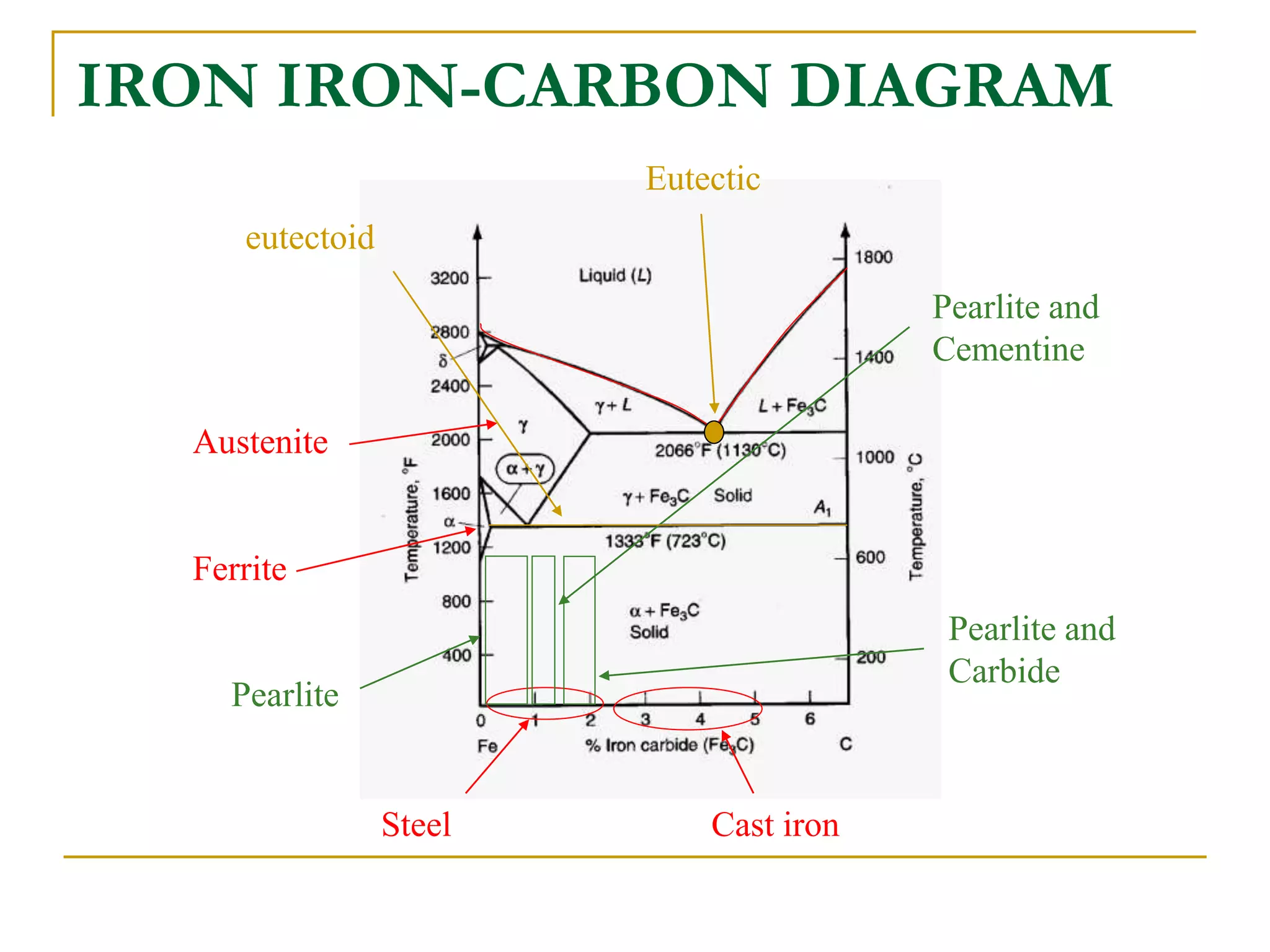
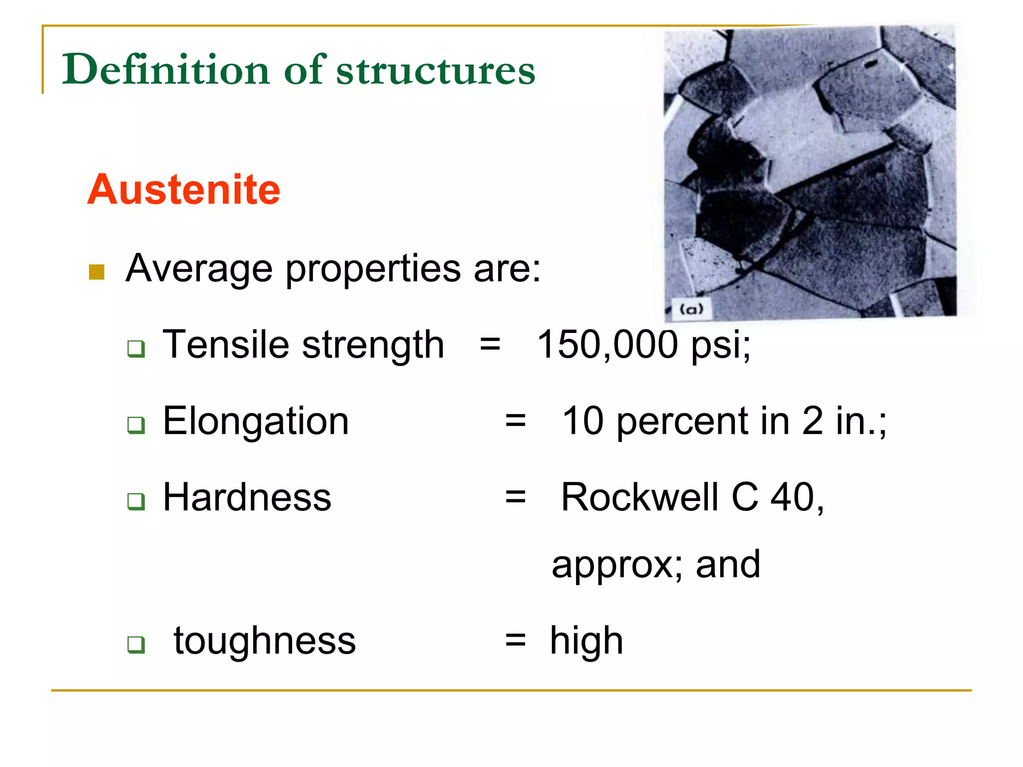
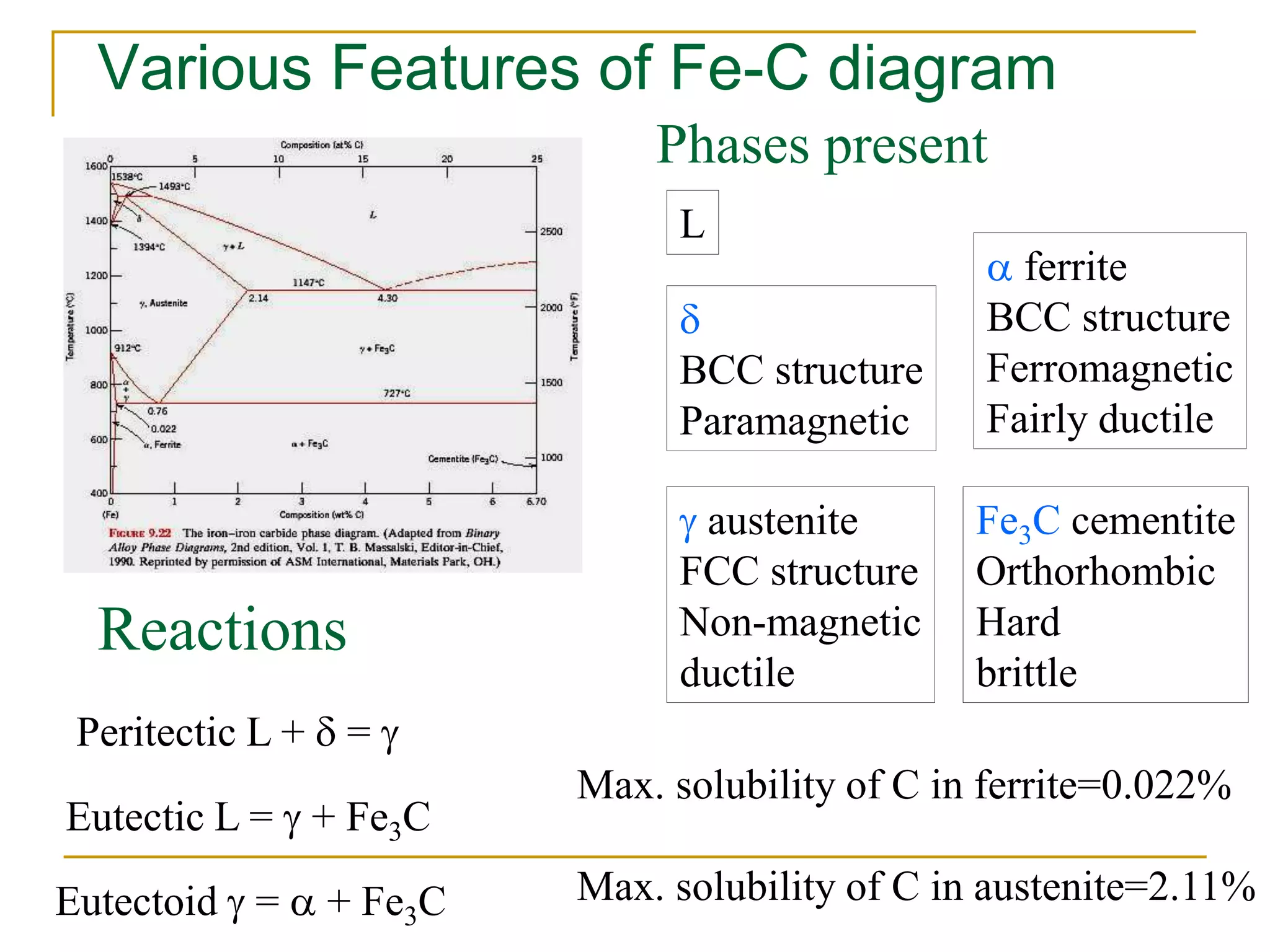
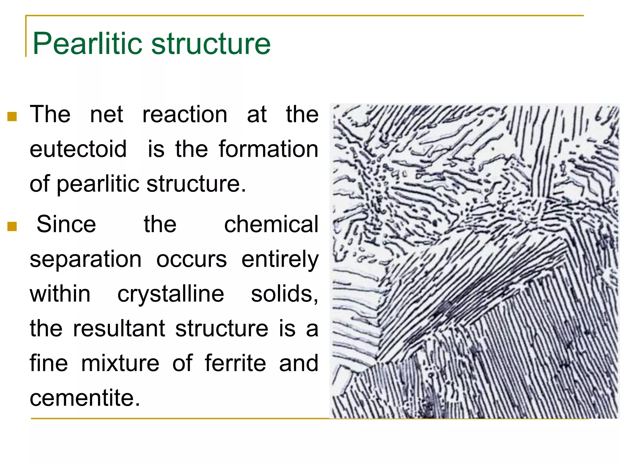
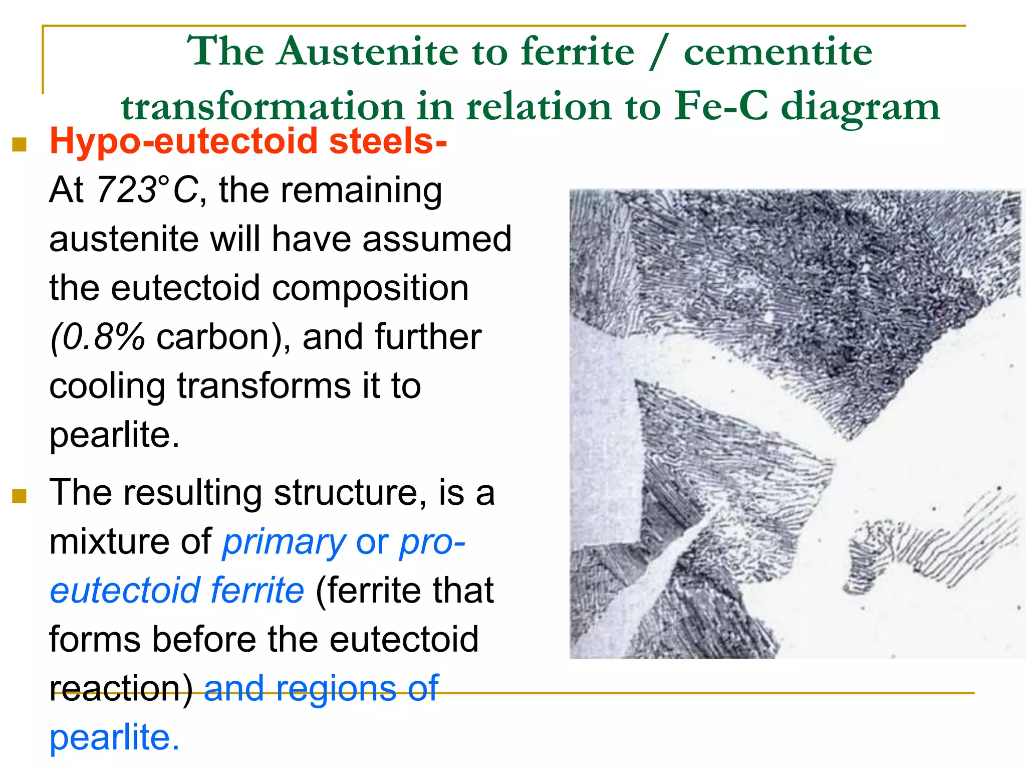
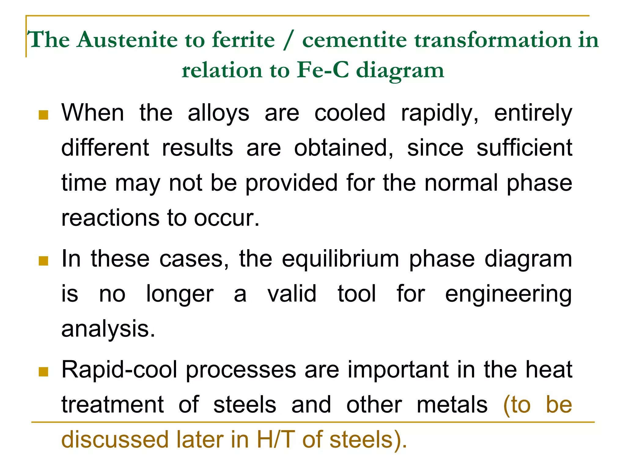
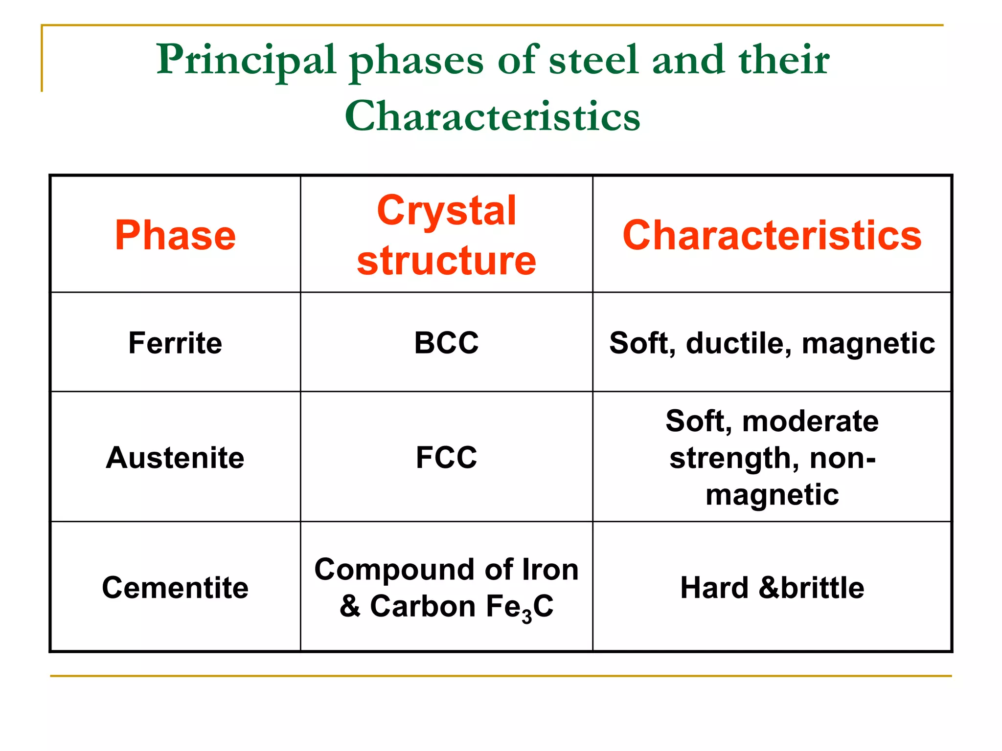
IRON IRON-CARBON
DIAGRAM
IRON IRON-CARBON DIAGRAM
Ferrite
Austenite
Steel Cast iron
Pearlite
Pearlite and
Cementine
Pearlite and
Carbide
Eutectic
eutectoid
Outline
 Introduction
 Cooling curve for pure iron
 Definition of structures
 Iron-Carbon equilibrium phase diagram – Sketch
 The Iron-Iron Carbide Diagram - Explanation
 The Austenite to ferrite / cementite
transformation
 Nucleation & growth of pearlite
 Effect of C %age on the microstructure of steel
 Relationship b/w C %age & mechanical
properties of steel
Cooling curve for pure iron
Definition of structures
Various phases that appear on the
Iron-Carbon equilibrium phase
diagram are as under:
•Austenite
•Ferrite
•Pearlite
•Cementite
•Martensite*
•Ledeburite
Unit Cells of Various Metals
 FIGURE - The unit cell for (a) austentite, (b) ferrite, and (c) martensite.
The effect of the percentage of carbon (by weight) on the lattice dimensions
for martensite is shown in (d). Note the interstitial position of the carbon
atoms and the increase in dimension c with increasing carbon content.
Thus, the unit cell of martensite is in the shape of a rectangular prism.
Microstructure of different phases of steel
Definition of structures
 Ferrite is known as α solid solution.
 It is an interstitial solid solution of a small
amount of carbon dissolved in α (BCC) iron.
 stable form of iron below 912 deg.C
 The maximum solubility is 0.025 % C at
723C and it dissolves only 0.008 % C at
room temperature.
 It is the softest structure that appears on the
diagram.
Definition of structures
Ferrite
 Average properties are:
 Tensile strength = 40,000 psi;
 Elongation = 40 % in 2 in;
 Hardness > Rockwell C 0 or
> Rockwell B 90
Definition of structures
 Pearlite is the eutectoid mixture
containing 0.80 % C and is
formed at 723°C on very slow
cooling.
 It is a very fine platelike or
lamellar mixture of ferrite and
cementite.
 The white ferritic background or
matrix contains thin plates of
cementite (dark).
Definition of structures
Pearlite
 Average properties are:
 Tensile strength = 120,000 psi;
 Elongation = 20 % in 2 in.;
 Hardness = Rockwell C 20, Rockwell B
95-100, or BHN 250-300.
Definition of structures
 Austenite is an interstitial solid solution of
Carbon dissolved in  (F.C.C.) iron.
 Maximum solubility is 2.0 % C at 1130°C.
 High formability, most of heat treatments
begin with this single phase.
 It is normally not stable at room
temperature. But, under certain conditions it
is possible to obtain austenite at room
temperature.
Definition of structures
Austenite
 Average properties are:
 Tensile strength = 150,000 psi;
 Elongation = 10 percent in 2 in.;
 Hardness = Rockwell C 40,
approx; and
 toughness = high
Definition of structures
 Cementite or iron carbide, is very hard,
brittle intermetallic compound of iron &
carbon, as Fe3C, contains 6.67 % C.
 It is the hardest structure that appears on the
diagram, exact melting point unknown.
 Its crystal structure is orthorhombic.
 It is has
 low tensile strength (approx. 5,000 psi),
but
 high compressive strength.
Definition of structures
 Ledeburite is the eutectic
mixture of austenite and
cementite.
 It contains 4.3 percent C and is
formed at 1130°C.
Definition of structures
 Martensite - a super-saturated solid solution of
carbon in ferrite.
 It is formed when steel is cooled so rapidly that
the change from austenite to pearlite is
suppressed.
 The interstitial carbon atoms distort the BCC
ferrite into a BC-tetragonal structure (BCT).;
responsible for the hardness of quenched steel
The Iron-Iron Carbide Diagram
 A map of the temperature at which different
phase changes occur on very slow heating
and cooling in relation to Carbon, is called
Iron- Carbon Diagram.
 Iron- Carbon diagram shows
 the type of alloys formed under very slow
cooling,
 proper heat-treatment temperature and
 how the properties of steels and cast irons
can be radically changed by heat-treatment.
Various Features of Fe-C diagram
Peritectic L + d = 
Eutectic L =  + Fe3C
Eutectoid  = a + Fe3C
Phases present
L
Reactions
d
BCC structure
Paramagnetic
 austenite
FCC structure
Non-magnetic
ductile
a ferrite
BCC structure
Ferromagnetic
Fairly ductile
Fe3C cementite
Orthorhombic
Hard
brittle
Max. solubility of C in ferrite=0.022%
Max. solubility of C in austenite=2.11%
Three Phase Reactions
 Peritectic, at 1490 deg.C, with low wt% C
alloys (almost no engineering importance).
 Eutectic, at 1130 deg.C, with 4.3wt% C,
alloys called cast irons.
 Eutectoid, at 723 deg.C with eutectoid
composition of 0.8wt% C, two-phase mixture
(ferrite & cementite). They are steels.
How to read the Fe-C phase diagram
Ferrite
Austenite
Steel Cast iron
Pearlite
Pearlite and
Cementine
Pearlite and
Carbide
Eutectic
eutectoid
The Iron-Iron Carbide Diagram
The diagram shows three horizontal lines which
indicate isothermal reactions (on cooling /
heating):
 First horizontal line is at 1490°C, where peritectic
reaction takes place:
Liquid + d ↔ austenite
 Second horizontal line is at 1130°C, where
eutectic reaction takes place:
liquid ↔ austenite + cementite
 Third horizontal line is at 723°C, where eutectoid
reaction takes place:
austenite ↔ pearlite (mixture of ferrite &
cementite)
Delta region of Fe-Fe carbide diagram
Liquid + d ↔ austenite
Ferrite region of
Fe-Fe Carbide
diagram
Simplified Iron-Carbon phase diagram
austenite ↔ pearlite (mixture of ferrite & cementite)
The Austenite to ferrite / cementite transformation in
relation to Fe-C diagram
The Austenite to ferrite / cementite
transformation in relation to Fe-C diagram
In order to understand the transformation
processes, consider a steel of the eutectoid
composition. 0.8% carbon, being slow cooled
along line x-x‘.
 At the upper temperatures, only austenite is
present, with the 0.8% carbon being dissolved
in solid solution within the FCC. When the steel
cools through 723°C, several changes occur
simultaneously.
The Austenite to ferrite / cementite
transformation in relation to Fe-C diagram
 The iron wants to change crystal
structure from the FCC austenite to the
BCC ferrite, but the ferrite can only
contain 0.02% carbon in solid solution.
 The excess carbon is rejected and
forms the carbon-rich intermetallic
known as cementite.
Pearlitic structure
 The net reaction at the
eutectoid is the formation
of pearlitic structure.
 Since the chemical
separation occurs entirely
within crystalline solids,
the resultant structure is a
fine mixture of ferrite and
cementite.
Schematic picture of the formation and
growth of pearlite
Ferrite
Cementite
Austenite
boundary
Nucleation & growth of pearlite
The Austenite to ferrite / cementite transformation in
relation to Fe-C diagram
 Hypo-eutectoid steels: Steels having less than
0.8% carbon are called hypo-eutectoid steels
(hypo means "less than").
 Consider the cooling of a typical hypo-eutectoid
alloy along line y-y‘.
 At high temperatures the material is entirely
austenite.
 Upon cooling it enters a region where the stable
phases are ferrite and austenite.
 The low-carbon ferrite nucleates and grows,
leaving the remaining austenite richer in carbon.
The Austenite to ferrite / cementite
transformation in relation to Fe-C diagram
 Hypo-eutectoid steels-
At 723°C, the remaining
austenite will have assumed
the eutectoid composition
(0.8% carbon), and further
cooling transforms it to
pearlite.
 The resulting structure, is a
mixture of primary or pro-
eutectoid ferrite (ferrite that
forms before the eutectoid
reaction) and regions of
pearlite.
The Austenite to ferrite / cementite transformation in
relation to Fe-C diagram
 Hyper-eutectoid steels (hyper means
"greater than") are those that contain more
than the eutectoid amount of Carbon.
 When such a steel cools, as along line z-z' ,
the process is similar to the hypo-eutectoid
steel, except that the primary or pro-eutectoid
phase is now cementite instead of ferrite.
The Austenite to ferrite / cementite transformation in
relation to Fe-C diagram
 As the carbon-rich phase nucleates and grows,
the remaining austenite decreases in carbon
content, again reaching the eutectoid
composition at 723°C.
 This austenite transforms to pearlite upon slow
cooling through the eutectoid temperature.
 The resulting structure consists of primary
cementite and pearlite.
 The continuous network of primary cementite
will cause the material to be extremely brittle.
The Austenite to ferrite / cementite transformation in
relation to Fe-C diagram
Hypo-eutectoid steel showing primary cementite along grain
boundaries pearlite
The Austenite to ferrite / cementite
transformation in relation to Fe-C diagram
 It should be noted that the transitions
as discussed, are for equilibrium
conditions, as a result of slow cooling.
 Upon slow heating the transitions will
occur in the reverse manner.
The Austenite to ferrite / cementite transformation in
relation to Fe-C diagram
 When the alloys are cooled rapidly, entirely
different results are obtained, since sufficient
time may not be provided for the normal phase
reactions to occur.
 In these cases, the equilibrium phase diagram
is no longer a valid tool for engineering
analysis.
 Rapid-cool processes are important in the heat
treatment of steels and other metals (to be
discussed later in H/T of steels).
Principal phases of steel and their
Characteristics
Phase
Crystal
structure
Characteristics
Ferrite BCC Soft, ductile, magnetic
Austenite FCC
Soft, moderate
strength, non-
magnetic
Cementite
Compound of Iron
& Carbon Fe3C
Hard &brittle
24
• Teutectoid changes: • Ceutectoid changes:
Alloying Steel with more Elements
Cast Irons
-Iron-Carbon alloys of
2.11%C or more are cast
irons.
-Typical composition: 2.0-
4.0%C,0.5-3.0% Si, less
than 1.0% Mn and less
than 0.2% S.
-Si-substitutes partially for C
and promotes formation of
graphite as the carbon
rich component instead
Fe3C.
Applications
 It is used tailor properties of steel and to heat
treat them.
 It is also used for comparison of crystal
structures for metallurgists in case of rupture
or fatigue
Conclusion
Thanks

IRON- IRON CARBIDE DIAGRAM.ppt

  • 1.
  • 2.
    IRON IRON-CARBON DIAGRAM Ferrite Austenite SteelCast iron Pearlite Pearlite and Cementine Pearlite and Carbide Eutectic eutectoid
  • 3.
    Outline  Introduction  Coolingcurve for pure iron  Definition of structures  Iron-Carbon equilibrium phase diagram – Sketch  The Iron-Iron Carbide Diagram - Explanation  The Austenite to ferrite / cementite transformation  Nucleation & growth of pearlite  Effect of C %age on the microstructure of steel  Relationship b/w C %age & mechanical properties of steel
  • 4.
  • 5.
    Definition of structures Variousphases that appear on the Iron-Carbon equilibrium phase diagram are as under: •Austenite •Ferrite •Pearlite •Cementite •Martensite* •Ledeburite
  • 6.
    Unit Cells ofVarious Metals  FIGURE - The unit cell for (a) austentite, (b) ferrite, and (c) martensite. The effect of the percentage of carbon (by weight) on the lattice dimensions for martensite is shown in (d). Note the interstitial position of the carbon atoms and the increase in dimension c with increasing carbon content. Thus, the unit cell of martensite is in the shape of a rectangular prism.
  • 7.
  • 8.
    Definition of structures Ferrite is known as α solid solution.  It is an interstitial solid solution of a small amount of carbon dissolved in α (BCC) iron.  stable form of iron below 912 deg.C  The maximum solubility is 0.025 % C at 723C and it dissolves only 0.008 % C at room temperature.  It is the softest structure that appears on the diagram.
  • 9.
    Definition of structures Ferrite Average properties are:  Tensile strength = 40,000 psi;  Elongation = 40 % in 2 in;  Hardness > Rockwell C 0 or > Rockwell B 90
  • 10.
    Definition of structures Pearlite is the eutectoid mixture containing 0.80 % C and is formed at 723°C on very slow cooling.  It is a very fine platelike or lamellar mixture of ferrite and cementite.  The white ferritic background or matrix contains thin plates of cementite (dark).
  • 11.
    Definition of structures Pearlite Average properties are:  Tensile strength = 120,000 psi;  Elongation = 20 % in 2 in.;  Hardness = Rockwell C 20, Rockwell B 95-100, or BHN 250-300.
  • 12.
    Definition of structures Austenite is an interstitial solid solution of Carbon dissolved in  (F.C.C.) iron.  Maximum solubility is 2.0 % C at 1130°C.  High formability, most of heat treatments begin with this single phase.  It is normally not stable at room temperature. But, under certain conditions it is possible to obtain austenite at room temperature.
  • 13.
    Definition of structures Austenite Average properties are:  Tensile strength = 150,000 psi;  Elongation = 10 percent in 2 in.;  Hardness = Rockwell C 40, approx; and  toughness = high
  • 14.
    Definition of structures Cementite or iron carbide, is very hard, brittle intermetallic compound of iron & carbon, as Fe3C, contains 6.67 % C.  It is the hardest structure that appears on the diagram, exact melting point unknown.  Its crystal structure is orthorhombic.  It is has  low tensile strength (approx. 5,000 psi), but  high compressive strength.
  • 15.
    Definition of structures Ledeburite is the eutectic mixture of austenite and cementite.  It contains 4.3 percent C and is formed at 1130°C.
  • 16.
    Definition of structures Martensite - a super-saturated solid solution of carbon in ferrite.  It is formed when steel is cooled so rapidly that the change from austenite to pearlite is suppressed.  The interstitial carbon atoms distort the BCC ferrite into a BC-tetragonal structure (BCT).; responsible for the hardness of quenched steel
  • 17.
    The Iron-Iron CarbideDiagram  A map of the temperature at which different phase changes occur on very slow heating and cooling in relation to Carbon, is called Iron- Carbon Diagram.  Iron- Carbon diagram shows  the type of alloys formed under very slow cooling,  proper heat-treatment temperature and  how the properties of steels and cast irons can be radically changed by heat-treatment.
  • 18.
    Various Features ofFe-C diagram Peritectic L + d =  Eutectic L =  + Fe3C Eutectoid  = a + Fe3C Phases present L Reactions d BCC structure Paramagnetic  austenite FCC structure Non-magnetic ductile a ferrite BCC structure Ferromagnetic Fairly ductile Fe3C cementite Orthorhombic Hard brittle Max. solubility of C in ferrite=0.022% Max. solubility of C in austenite=2.11%
  • 19.
    Three Phase Reactions Peritectic, at 1490 deg.C, with low wt% C alloys (almost no engineering importance).  Eutectic, at 1130 deg.C, with 4.3wt% C, alloys called cast irons.  Eutectoid, at 723 deg.C with eutectoid composition of 0.8wt% C, two-phase mixture (ferrite & cementite). They are steels.
  • 20.
    How to readthe Fe-C phase diagram Ferrite Austenite Steel Cast iron Pearlite Pearlite and Cementine Pearlite and Carbide Eutectic eutectoid
  • 21.
    The Iron-Iron CarbideDiagram The diagram shows three horizontal lines which indicate isothermal reactions (on cooling / heating):  First horizontal line is at 1490°C, where peritectic reaction takes place: Liquid + d ↔ austenite  Second horizontal line is at 1130°C, where eutectic reaction takes place: liquid ↔ austenite + cementite  Third horizontal line is at 723°C, where eutectoid reaction takes place: austenite ↔ pearlite (mixture of ferrite & cementite)
  • 22.
    Delta region ofFe-Fe carbide diagram Liquid + d ↔ austenite
  • 23.
    Ferrite region of Fe-FeCarbide diagram
  • 24.
    Simplified Iron-Carbon phasediagram austenite ↔ pearlite (mixture of ferrite & cementite)
  • 25.
    The Austenite toferrite / cementite transformation in relation to Fe-C diagram
  • 26.
    The Austenite toferrite / cementite transformation in relation to Fe-C diagram In order to understand the transformation processes, consider a steel of the eutectoid composition. 0.8% carbon, being slow cooled along line x-x‘.  At the upper temperatures, only austenite is present, with the 0.8% carbon being dissolved in solid solution within the FCC. When the steel cools through 723°C, several changes occur simultaneously.
  • 27.
    The Austenite toferrite / cementite transformation in relation to Fe-C diagram  The iron wants to change crystal structure from the FCC austenite to the BCC ferrite, but the ferrite can only contain 0.02% carbon in solid solution.  The excess carbon is rejected and forms the carbon-rich intermetallic known as cementite.
  • 28.
    Pearlitic structure  Thenet reaction at the eutectoid is the formation of pearlitic structure.  Since the chemical separation occurs entirely within crystalline solids, the resultant structure is a fine mixture of ferrite and cementite.
  • 29.
    Schematic picture ofthe formation and growth of pearlite Ferrite Cementite Austenite boundary
  • 30.
  • 31.
    The Austenite toferrite / cementite transformation in relation to Fe-C diagram  Hypo-eutectoid steels: Steels having less than 0.8% carbon are called hypo-eutectoid steels (hypo means "less than").  Consider the cooling of a typical hypo-eutectoid alloy along line y-y‘.  At high temperatures the material is entirely austenite.  Upon cooling it enters a region where the stable phases are ferrite and austenite.  The low-carbon ferrite nucleates and grows, leaving the remaining austenite richer in carbon.
  • 32.
    The Austenite toferrite / cementite transformation in relation to Fe-C diagram  Hypo-eutectoid steels- At 723°C, the remaining austenite will have assumed the eutectoid composition (0.8% carbon), and further cooling transforms it to pearlite.  The resulting structure, is a mixture of primary or pro- eutectoid ferrite (ferrite that forms before the eutectoid reaction) and regions of pearlite.
  • 33.
    The Austenite toferrite / cementite transformation in relation to Fe-C diagram  Hyper-eutectoid steels (hyper means "greater than") are those that contain more than the eutectoid amount of Carbon.  When such a steel cools, as along line z-z' , the process is similar to the hypo-eutectoid steel, except that the primary or pro-eutectoid phase is now cementite instead of ferrite.
  • 34.
    The Austenite toferrite / cementite transformation in relation to Fe-C diagram  As the carbon-rich phase nucleates and grows, the remaining austenite decreases in carbon content, again reaching the eutectoid composition at 723°C.  This austenite transforms to pearlite upon slow cooling through the eutectoid temperature.  The resulting structure consists of primary cementite and pearlite.  The continuous network of primary cementite will cause the material to be extremely brittle.
  • 35.
    The Austenite toferrite / cementite transformation in relation to Fe-C diagram Hypo-eutectoid steel showing primary cementite along grain boundaries pearlite
  • 36.
    The Austenite toferrite / cementite transformation in relation to Fe-C diagram  It should be noted that the transitions as discussed, are for equilibrium conditions, as a result of slow cooling.  Upon slow heating the transitions will occur in the reverse manner.
  • 37.
    The Austenite toferrite / cementite transformation in relation to Fe-C diagram  When the alloys are cooled rapidly, entirely different results are obtained, since sufficient time may not be provided for the normal phase reactions to occur.  In these cases, the equilibrium phase diagram is no longer a valid tool for engineering analysis.  Rapid-cool processes are important in the heat treatment of steels and other metals (to be discussed later in H/T of steels).
  • 38.
    Principal phases ofsteel and their Characteristics Phase Crystal structure Characteristics Ferrite BCC Soft, ductile, magnetic Austenite FCC Soft, moderate strength, non- magnetic Cementite Compound of Iron & Carbon Fe3C Hard &brittle
  • 39.
    24 • Teutectoid changes:• Ceutectoid changes: Alloying Steel with more Elements
  • 40.
    Cast Irons -Iron-Carbon alloysof 2.11%C or more are cast irons. -Typical composition: 2.0- 4.0%C,0.5-3.0% Si, less than 1.0% Mn and less than 0.2% S. -Si-substitutes partially for C and promotes formation of graphite as the carbon rich component instead Fe3C.
  • 41.
    Applications  It isused tailor properties of steel and to heat treat them.  It is also used for comparison of crystal structures for metallurgists in case of rupture or fatigue
  • 42.
  • 43.