SlideShare a Scribd company logo
1 of 14
Download to read offline
1
School of Mechanical Engineering, VIT - Vellore
• In their simplest form, steels are alloys of Iron (Fe) and Carbon (C).
• The Fe-C phase diagram is a fairly complex one, but we will only consider the steel part of
the diagram, up to
around 7% Carbon.
The Iron–Iron Carbide (Fe–Fe3C) Phase Diagram
1
• Phases present
 α-ferrite,
 γ-ferrite,
 δ-ferrite,
 Fe3C (iron carbide
or cementite)
 Fe-C liquid solution
School of Mechanical Engineering, VIT - Vellore
 α-ferrite - solid solution of C in BCC Fe
• Stable form of iron at room temperature.
• The maximum solubility of C is 0.022 wt%
• Transforms to FCC γ-austenite at 912 °C
 γ-austenite - solid solution of C in FCC Fe
• The maximum solubility of C is 2.14 wt %.
• Transforms to BCC δ-ferrite at 1395 °C
• Is not stable below the eutectic
temperature (727 °C) unless cooled
rapidly
 δ-ferrite - solid solution of C in BCC Fe
• The same structure as α-ferrite
• Stable only at high T, above 1394 °C
• Melts at 1538 °C
Phases in Fe–Fe3C Phase Diagram
2
 Fe3C (iron carbide or cementite)
• This intermetallic compound is
metastable, it remains as a compound
indefinitely at room T, but decomposes
(very slowly, within several years) into α-
Fe and C (graphite) at 650 - 700 °C
 Fe-C liquid solution
α-ferrite austenite
2
School of Mechanical Engineering, VIT - Vellore
• Pure iron when heated experiences two changes in crystal structure before it melts.
• At room temperature the stable form, ferrite (α iron) has a BCC crystal structure.
• Ferrite experiences a polymorphic transformation to FCC austenite (γ iron) at 912 ˚C (1674 ˚F).
• At 1394˚C (2541˚F) austenite reverts back to BCC phase δ ferrite and melts at 1538˚C (2800˚F).
• Iron carbide (cementite or Fe3C) an
intermediate compound is formed
at 6.7 wt% C.
• Typically, all steels and cast irons have
carbon contents less than 6.7 wt% C.
• Carbon is an interstitial impurity in iron
and forms a solid solution with the
α, β, γ phases.
Changes in Crystal Structure
3
School of Mechanical Engineering, VIT - Vellore
• C is an interstitial impurity in Fe. It forms a solid solution with α, β, γ phases of iron
• Maximum solubility in BCC α-ferrite is limited (max. 0.022 wt% at 727 °C) – which can be
explained by the shape and size of the BCC interstitial positions, which make it difficult to
accommodate the carbon atoms. BCC has relatively small interstitial positions. Even though
present in relatively low concentrations, carbon significantly influences the mechanical
properties of ferrite
• Maximum solubility in FCC austenite is 2.14 wt% at 1147 °C - FCC has larger interstitial
positions
• Mechanical properties: Cementite is very hard and brittle - can strengthen steels.
Mechanical properties also depend on the microstructure, that is, how ferrite and cementite
are mixed.
• Magnetic properties: α -ferrite is magnetic below 768 °C, austenite is non-magnetic
A few comments on Fe–Fe3C system
4
3
School of Mechanical Engineering, VIT - Vellore
• Three types of ferrous alloys:
– Iron:
• less than 0.008 wt % C in α−ferrite at room T
– Steels:
• 0.008 - 2.14 wt % C (usually < 1 wt % );
• α-ferrite + Fe3C at room T
– Cast iron:
• 2.14 - 6.7 wt % (usually < 4.5 wt %)
Classification - Types of ferrous alloys
5
School of Mechanical Engineering, VIT - Vellore
• In binary phase diagrams, a horizontal line always indicates an invariant reaction.
• Three invariant reactions are present in Iron–Iron Carbide (Fe–Fe3C) Phase Diagram.
1. Peritectic reaction
2. Eutectic reaction
3. Eutectoid reaction
Invariant Reactions in Fe–Fe3C System
6
1493 °C
1150 °C
727 °C
γ
δ
4
School of Mechanical Engineering, VIT - Vellore
Peritectic, involves the following phase transformation.
L(0.53% C) + δ (BCC Ferrite of 0.1% C) → γ (FCC Austenite of 0.18% C)
• The maximum solubility of carbon in BCC δ-iron is 0.1% (point M)
whereas in FCC γ-iron, it is greater. The presence of carbon
influences the allotropic changes. As carbon is increased or added
to the iron, the temperature increases from 1400ºC to 1493ºC at
0.1% carbon.
Peritectic reaction - Fe–Fe3C System
7
M
N
P-
B
School of Mechanical Engineering, VIT - Vellore
Consider the portion NMPB in Peritectic Reaction
• On cooling, the portion NM represents the beginning of the crystal
structure change from BCC δ iron to FCC γ iron for alloys
containing less than 0.1% carbon.
• Line MP represents the beginning of crystal structure change by
means of peritectic reaction for the alloys between 0.1 & 0.18%
Carbon.
• Line NP represents the end of crystal structure change for alloys
containing less than 0.18% C.
• Portion PB represents the end of crystal structure by means of
peritectic reaction for the alloys between 0.18- 0.5% carbon. Here
the reaction takes place isothermally (i.e.) at constant temperature.
• At the peritectic reaction point, liquid of 0.53% C combines with δ
ferrite of 0.1% C to form FCC γ austenite of 0.18% C
Peritectic reaction - Fe–Fe3C System
8
M
N
P-
B
5
School of Mechanical Engineering, VIT - Vellore
• Eutectic Point is given by point E (refer fig.2) exists at 4.3% Carbon
and at the temperature of 1147°C.
• Horizontal line represents the eutectic temperature line and
whenever an alloy crosses the line must undergo the eutectic
reaction
• Any liquid that is present when this line is reached must solidify
now into very fine intimate mixture of two phases namely austenite
(γ) and cementite (Fe3C).
• The eutectic mixture has been given with the name LEDEBURITE
and the equation is given as
Eutectic reaction - Fe–Fe3C System
9
L
(4.3% C)
(FCC)
2.14% C
6.67%C
• The eutectic mixture is not usually seen in the microscope because the austenite is not stable at
room temperatures and must undergo another reaction during cooling
School of Mechanical Engineering, VIT - Vellore
• An alloy of eutectoid composition (0.76 wt% C) as it is cooled from a temperature within the phase
region, say, 800 °C—that is, beginning at point a and moving down the vertical line xx`.
• Initially, the alloy is composed entirely of the austenite
phase having a composition of 0.76 wt% C (Figure a).
As the alloy is cooled, no changes will occur until the
eutectoid temperature (727 °C) is reached.
Upon crossing this temperature to point b, the austenite
transforms to α and Fe3C) .
• This microstructure, represented schematically in
point b, is called pearlite (alternating layers or lamellae
of α and Fe3C.
Development of Microstructure - Fe–Fe3C System
10
6
School of Mechanical Engineering, VIT - Vellore
• Formation of pearlite structure
– Nucleating at γ grain boundary,
– growth by diffusion of C to achieve the compositions
of α and Fe3C (with structural changes)
– α lamellae much thick ( relative layer thickness
is approximately 8 to 1)
Pearlite
11
Redistribution of carbon
by diffusion
• Austenite – 0.76 wt% C;
• Ferrite - 0.022 wt% C
• Cementite - 6.70 wt% C
upper-critical-
temperature line
School of Mechanical Engineering, VIT - Vellore
• Composition C0 to the left of the eutectoid, between 0.022 and 0.76 wt% C; is termed a hypoeutectoid
(less than eutectoid) alloy.
• At about 875°C, point c, the microstructure will consist
entirely of grains of the γ phase (Fig c)
• Cooling to point d, at about 775°C, both α phase and
γ phase coexist (Fig d).
• Cooling from point d to e, just above the eutectoid but
still in the α + γ region, will produce an increased fraction
of the α phase and a microstructure similar to fig e,
the particles will have grown larger.
• As the temperature is lowered just below the eutectoid, to
point f, all the phase that was present at temperature Te
(and having the eutectoid composition) will transform
to pearlite,
Hypoeutectoid Alloys
12
7
School of Mechanical Engineering, VIT - Vellore
• In the austenite range, it is a uniform interstitial solid solution. Upon slow cooling, nothing happens until
the line MO is crossed at point d. This MO line is known as the upper-critical-temperature line on the
hypoeutectoid side.
Hypoeutectoid Alloys
13
• At d, ferrite must begin to form at the austenite grain
boundaries. Since ferrite can dissolve very little carbon,
in those areas that are changing to ferrite the carbon
must come out of solution before the atoms rearrange
themselves to BCC
• The carbon which comes out of solution is dissolved in
the remaining austenite, so that, as cooling progresses
and the amount of ferrite increases, the remaining
austenite becomes richer in carbon.
• Its carbon content is gradually moving down and to the
right along the MO line. Finally, the line NO is reached at
point f.
School of Mechanical Engineering, VIT - Vellore
• The ferrite phase will be present both in the pearlite and also as the phase that formed while
cooling through the α and γ phase region.
• The ferrite that is present in the pearlite is
called eutectoid ferrite,
whereas the other, that formed above Te, is
termed proeutectoid ferrite (meaning “pre- or
before eutectoid”)
Hypoeutectoid Alloys
14
8
School of Mechanical Engineering, VIT - Vellore
• Compositions to the right of eutectoid (0.76 - 2.14 wt % C) hypereutectoid (more than
eutectoid -Greek) alloys.
γ → γ + Fe3C → α + Fe3C
• Hypereutectoid alloys contain proeutectoid cementite
(formed above the eutectoid temperature) plus pearlite
that contain eutectoid ferrite and cementite.
Hypereutectoid Alloys
15
School of Mechanical Engineering, VIT - Vellore
• In the austenite range, this alloy consists of a uniform FCC solid solution with each grain containing 1.0
percent carbon dissolved interstitially.
Hypereutectoid Alloys
16
• Upon slow cooling, nothing happens until the line OP is
crossed at point h. This line is called upper-critical-
temperature line on the hypereutectoid side.
• The OP line shows the maximum amount of carbon that can
be dissolved in austenite as a function of temperature.
• Above the OP line, austenite is an unsaturated solid
solution.
• At h, the austenite is saturated in carbon. As the
temperature is decreased, the carbon content of the
austenite, that is, the maximum amount of carbon that can
be dissolved in austenite, moves down along OP line
towards point O.
• Therefore, as the temperature decreases from h to i, the
excess carbon above the amount required to saturate
austenite is precipitated as cementite primarily along the
grain boundaries.
• Finally, the eutectoid line is reached at i. This line is called
the lower-critical-temperature line on the hypereutectoid side
9
School of Mechanical Engineering, VIT - Vellore
Development of Microstructure - Fe–Fe3C System
17
Eutectoid steel
α+Fe3C
Pearlite
Hypoeutectoid steel
α+Fe3C
Pearlite +
proeutectoid ferrite
Hypereutectoid steel
α+Fe3C
Pearlite +
proeutectoid cementite
School of Mechanical Engineering, VIT - Vellore
How to calculate the relative amounts of proeutectoid phase (α or Fe3C) and pearlite?
• Application of the lever rule with tie line, that extends from the eutectoid composition (0.76 wt% C)
– to α – (α + Fe3C) boundary (0.022 wt% C) for hypoeutectoid alloys and
– to (α + Fe3C) – Fe3C boundary (6.7 wt% C) for hypereutectoid alloys.
Development of Microstructure - Fe–Fe3C System
18
• Fraction of α phase is determined
by application of the lever rule
across the entire (α + Fe3C) phase.
10
School of Mechanical Engineering, VIT - Vellore
Example for hypoeutectoid alloy with composition
• Fraction of pearlite:
• Fraction of proeutectoid ferrite α’:
Development of Microstructure - Fe–Fe3C System
19
74
.
0
022
.
0
022
.
0
76
.
0
022
.
0 '
0
'
0 −
=
−
−
=
+
=
C
C
U
T
T
WP
74
.
0
76
.
0
022
.
0
76
.
0
76
.
0 '
0
'
0
'
C
C
U
T
U
W
−
=
−
−
=
+
=
α
'
0
C
School of Mechanical Engineering, VIT - Vellore
Example for hypereutectoid alloy with composition
• Fraction of pearlite:
• Fraction of proeutectoid cementite:
Development of Microstructure - Fe–Fe3C System
20
94
.
5
70
.
6
76
.
0
70
.
6
70
.
6 '
1
'
1 C
C
X
V
X
WP
−
=
−
−
=
+
=
94
.
5
76
.
0
76
.
0
70
.
6
76
.
0 '
1
'
1
3
−
=
−
−
=
+
=
C
C
X
V
V
W C
Fe
'
1
C
11
School of Mechanical Engineering, VIT - Vellore
Determination of relative amount of ferrite, cementite and pearlite
21
School of Mechanical Engineering, VIT - Vellore
Determination of relative amount of ferrite, cementite and pearlite
22
12
School of Mechanical Engineering, VIT - Vellore
Determination of relative amount of ferrite, cementite and pearlite
23
School of Mechanical Engineering, VIT - Vellore
• The microstructural development of iron–carbon alloys it has been assumed that, upon
cooling, conditions of metastable equilibrium have been continuously maintained; that is,
sufficient time has been allowed at each new temperature for any necessary adjustment in
phase compositions and relative amounts as predicted from the Fe–Fe3C phase diagram.
Influence of other Alloying Elements - Teutectoid changes
24
Fig 1: The dependence of eutectoid
temperature on alloy concentration for
several alloying elements in steel
• These cooling rates are impractically slow and
really unnecessary; in fact, on many occasions
nonequilibrium conditions are desirable. Two
nonequilibrium effects of practical importance are
1. the occurrence of phase changes or
transformations at temperatures other than those
predicted by phase boundary lines on the phase
diagram, and
2. the existence at room temperature of non-
equilibrium phases that do not appear on the
phase diagram.
13
School of Mechanical Engineering, VIT - Vellore
• Additions of other alloying elements (Cr, Ni,Ti, etc.) bring about rather dramatic changes in
the binary iron–iron carbide phase diagram, Fig 1. The extent of these alterations of the
positions of phase boundaries and the shapes of the phase fields depends on the particular
alloying element and its concentration.
Influence of other Alloying Elements - Ceutectoid changes
25
Fig 2: The dependence of eutectoid
composition (wt% C) on alloy concentration
for several alloying elements in steel.
• One of the important changes is the shift in position of
the eutectoid with respect to temperature and to carbon
concentration. Fig 1 and 2, which plot the eutectoid
temperature and eutectoid composition (in wt% C) as a
function of concentration for several other alloying
elements. Thus, other alloy additions alter not only the
temperature of the eutectoid reaction but also the relative
fractions of pearlite and the proeutectoid phase that form.
Steels are normally alloyed for other reasons, however-
usually either to improve their corrosion resistance or to
render them amenable to heat treatment
School of Mechanical Engineering, VIT - Vellore
• Cementite (Fe3C)
– Contains 6.67% wt of Carbon
– Hard, Brittle Interstitial compound
– Tensile strength – 5000 psi approx. and has high compressive strength
– Crystal structure is orthorhombic
• Austenite (γ)
– Interstitial solid solution of carbon
– Has FCC crystal structure – can accommodate more carbon than ferrite
– Max. solubility of carbon in this phase is 2% at 1148 °C and lowers to 0.8% at 723 °C
– Tensile strength – 1,50,000 psi; Elongation – 2% in 2”
– Hardness – 40 HRC
– Not normally stable at room temperatures
Definitions of structures
26
14
School of Mechanical Engineering, VIT - Vellore
• α - Ferrite
– Interstitial solid solution of carbon in BCC crystal lattice
– As indicated in the Iron- Iron carbide equilibrium diagram, carbon is only slightly soluble
in -Ferrite and has the solubility of 0.025% at 723 °C
– Softest structure that appears on the diagram
– Average Props : TS – 40000 psi, Hardness – 90BHN
• Pearlite (α + Fe3C)
– Eutectoid mixture containing 0.8% Carbon and is formed at 723 °C on very slow cooling
– Microstructure has very fine plate like / lamellar structure
– Average Props : TS – 120000 psi, Hardness – 20HRC
Definitions of structures
27

More Related Content

What's hot

Lect-4 Iron Carbon Equilibrium Diagram
Lect-4 Iron Carbon Equilibrium DiagramLect-4 Iron Carbon Equilibrium Diagram
Lect-4 Iron Carbon Equilibrium Diagramrambansal37
 
Iron iron carbon equilibrium diagram
Iron iron carbon equilibrium diagramIron iron carbon equilibrium diagram
Iron iron carbon equilibrium diagramRushikesh Raval
 
Iron Iron-carbide Equilibrium Phase Dia Gram
Iron Iron-carbide Equilibrium Phase Dia GramIron Iron-carbide Equilibrium Phase Dia Gram
Iron Iron-carbide Equilibrium Phase Dia GramGulfam Hussain
 
Ch 27.5 iron carbon equilibrium diagram
Ch 27.5 iron carbon equilibrium diagramCh 27.5 iron carbon equilibrium diagram
Ch 27.5 iron carbon equilibrium diagramNandan Choudhary
 
iron-iron carbide Phase diagrams
iron-iron carbide Phase diagramsiron-iron carbide Phase diagrams
iron-iron carbide Phase diagramsWaheed Hassan
 
Iron iron carbide diagram By Hariprasad
Iron iron carbide diagram By HariprasadIron iron carbide diagram By Hariprasad
Iron iron carbide diagram By HariprasadSachin Hariprasad
 
Iron carbon diagram presentation
Iron carbon diagram presentationIron carbon diagram presentation
Iron carbon diagram presentationSURESH M. PATEL
 
Iron corbon phase diagram
Iron  corbon phase diagramIron  corbon phase diagram
Iron corbon phase diagramshaiksaleem55
 
Iron iron-carbide phase diagram
Iron iron-carbide phase diagramIron iron-carbide phase diagram
Iron iron-carbide phase diagramTaral Soliya
 
Iron Carbon Equilibrium Diagram
Iron Carbon Equilibrium DiagramIron Carbon Equilibrium Diagram
Iron Carbon Equilibrium DiagramAditi Rana
 
Iron Carbon Phase Diagram
Iron Carbon Phase DiagramIron Carbon Phase Diagram
Iron Carbon Phase DiagramJose Surendran
 
Heat treatment, phases, microstructures and its properties
Heat treatment, phases, microstructures and its propertiesHeat treatment, phases, microstructures and its properties
Heat treatment, phases, microstructures and its propertiesHitesh Basitti
 

What's hot (19)

Iron Iron-Carbide Diagram(MSM)
Iron Iron-Carbide Diagram(MSM)Iron Iron-Carbide Diagram(MSM)
Iron Iron-Carbide Diagram(MSM)
 
Lect-4 Iron Carbon Equilibrium Diagram
Lect-4 Iron Carbon Equilibrium DiagramLect-4 Iron Carbon Equilibrium Diagram
Lect-4 Iron Carbon Equilibrium Diagram
 
Iron iron carbon equilibrium diagram
Iron iron carbon equilibrium diagramIron iron carbon equilibrium diagram
Iron iron carbon equilibrium diagram
 
Phase diagram
Phase diagramPhase diagram
Phase diagram
 
IRON-IRON CARBIDE Phase Diagram
IRON-IRON CARBIDE Phase DiagramIRON-IRON CARBIDE Phase Diagram
IRON-IRON CARBIDE Phase Diagram
 
Thép
ThépThép
Thép
 
Iron Iron-carbide Equilibrium Phase Dia Gram
Iron Iron-carbide Equilibrium Phase Dia GramIron Iron-carbide Equilibrium Phase Dia Gram
Iron Iron-carbide Equilibrium Phase Dia Gram
 
Ch 27.5 iron carbon equilibrium diagram
Ch 27.5 iron carbon equilibrium diagramCh 27.5 iron carbon equilibrium diagram
Ch 27.5 iron carbon equilibrium diagram
 
iron-iron carbide Phase diagrams
iron-iron carbide Phase diagramsiron-iron carbide Phase diagrams
iron-iron carbide Phase diagrams
 
Iron iron carbide diagram By Hariprasad
Iron iron carbide diagram By HariprasadIron iron carbide diagram By Hariprasad
Iron iron carbide diagram By Hariprasad
 
Iron carbon diagram presentation
Iron carbon diagram presentationIron carbon diagram presentation
Iron carbon diagram presentation
 
Phase diagram
Phase diagramPhase diagram
Phase diagram
 
Iron corbon phase diagram
Iron  corbon phase diagramIron  corbon phase diagram
Iron corbon phase diagram
 
Iron iron-carbide phase diagram
Iron iron-carbide phase diagramIron iron-carbide phase diagram
Iron iron-carbide phase diagram
 
Iron Carbon Equilibrium Diagram
Iron Carbon Equilibrium DiagramIron Carbon Equilibrium Diagram
Iron Carbon Equilibrium Diagram
 
Iron Carbon Phase Diagram
Iron Carbon Phase DiagramIron Carbon Phase Diagram
Iron Carbon Phase Diagram
 
Heat treatment, phases, microstructures and its properties
Heat treatment, phases, microstructures and its propertiesHeat treatment, phases, microstructures and its properties
Heat treatment, phases, microstructures and its properties
 
Ironcarbondia
IroncarbondiaIroncarbondia
Ironcarbondia
 
Iron carbon diagram presentation
Iron carbon diagram presentationIron carbon diagram presentation
Iron carbon diagram presentation
 

Similar to Fallsem2021 22 mee1005-eth_vl2021220102807_reference_material_ii_30-aug-2021_unit_ii_part_ii_[compatibility_mode] (1)

Similar to Fallsem2021 22 mee1005-eth_vl2021220102807_reference_material_ii_30-aug-2021_unit_ii_part_ii_[compatibility_mode] (1) (20)

diagram fasa fe-fe3c.pdf
diagram fasa fe-fe3c.pdfdiagram fasa fe-fe3c.pdf
diagram fasa fe-fe3c.pdf
 
Iron carbon diagram
Iron carbon diagramIron carbon diagram
Iron carbon diagram
 
Iron iron carbon diagram
Iron iron carbon diagramIron iron carbon diagram
Iron iron carbon diagram
 
IRON CARBON DIAGRAM PPT.pptx
IRON CARBON DIAGRAM PPT.pptxIRON CARBON DIAGRAM PPT.pptx
IRON CARBON DIAGRAM PPT.pptx
 
Iron carbon phase
Iron carbon phaseIron carbon phase
Iron carbon phase
 
Fe c
Fe cFe c
Fe c
 
Iron carbon phase
Iron carbon phaseIron carbon phase
Iron carbon phase
 
Diagram fe c (2)
Diagram fe c (2)Diagram fe c (2)
Diagram fe c (2)
 
13
1313
13
 
MENG-6B.pdf
MENG-6B.pdfMENG-6B.pdf
MENG-6B.pdf
 
IRON- IRON CARBIDE DIAGRAM.ppt
IRON- IRON CARBIDE DIAGRAM.pptIRON- IRON CARBIDE DIAGRAM.ppt
IRON- IRON CARBIDE DIAGRAM.ppt
 
Part-2 Leaning to plot Fe-c diagram-BNB-audio.ppt
Part-2 Leaning to plot Fe-c diagram-BNB-audio.pptPart-2 Leaning to plot Fe-c diagram-BNB-audio.ppt
Part-2 Leaning to plot Fe-c diagram-BNB-audio.ppt
 
Phase transformation physical metallurgy
Phase transformation physical metallurgyPhase transformation physical metallurgy
Phase transformation physical metallurgy
 
14691 a03e6 mse2
14691 a03e6 mse214691 a03e6 mse2
14691 a03e6 mse2
 
14691 a03e6 mse2
14691 a03e6 mse214691 a03e6 mse2
14691 a03e6 mse2
 
TTT curves and CCT curves relation with fatigue
TTT curves and CCT curves relation with fatigueTTT curves and CCT curves relation with fatigue
TTT curves and CCT curves relation with fatigue
 
L 07 a
L 07 aL 07 a
L 07 a
 
Power piont ch2 phase-transformation-in-metals (1)
Power piont   ch2 phase-transformation-in-metals (1)Power piont   ch2 phase-transformation-in-metals (1)
Power piont ch2 phase-transformation-in-metals (1)
 
5- Iron carbide diagram, A.pdf
5- Iron carbide diagram, A.pdf5- Iron carbide diagram, A.pdf
5- Iron carbide diagram, A.pdf
 
EMM lecture.ppt
EMM lecture.pptEMM lecture.ppt
EMM lecture.ppt
 

Recently uploaded

(RIA) Call Girls Bhosari ( 7001035870 ) HI-Fi Pune Escorts Service
(RIA) Call Girls Bhosari ( 7001035870 ) HI-Fi Pune Escorts Service(RIA) Call Girls Bhosari ( 7001035870 ) HI-Fi Pune Escorts Service
(RIA) Call Girls Bhosari ( 7001035870 ) HI-Fi Pune Escorts Serviceranjana rawat
 
Introduction to Multiple Access Protocol.pptx
Introduction to Multiple Access Protocol.pptxIntroduction to Multiple Access Protocol.pptx
Introduction to Multiple Access Protocol.pptxupamatechverse
 
Microscopic Analysis of Ceramic Materials.pptx
Microscopic Analysis of Ceramic Materials.pptxMicroscopic Analysis of Ceramic Materials.pptx
Microscopic Analysis of Ceramic Materials.pptxpurnimasatapathy1234
 
Call Girls in Nagpur Suman Call 7001035870 Meet With Nagpur Escorts
Call Girls in Nagpur Suman Call 7001035870 Meet With Nagpur EscortsCall Girls in Nagpur Suman Call 7001035870 Meet With Nagpur Escorts
Call Girls in Nagpur Suman Call 7001035870 Meet With Nagpur EscortsCall Girls in Nagpur High Profile
 
Introduction to IEEE STANDARDS and its different types.pptx
Introduction to IEEE STANDARDS and its different types.pptxIntroduction to IEEE STANDARDS and its different types.pptx
Introduction to IEEE STANDARDS and its different types.pptxupamatechverse
 
Decoding Kotlin - Your guide to solving the mysterious in Kotlin.pptx
Decoding Kotlin - Your guide to solving the mysterious in Kotlin.pptxDecoding Kotlin - Your guide to solving the mysterious in Kotlin.pptx
Decoding Kotlin - Your guide to solving the mysterious in Kotlin.pptxJoão Esperancinha
 
Call Girls Service Nagpur Tanvi Call 7001035870 Meet With Nagpur Escorts
Call Girls Service Nagpur Tanvi Call 7001035870 Meet With Nagpur EscortsCall Girls Service Nagpur Tanvi Call 7001035870 Meet With Nagpur Escorts
Call Girls Service Nagpur Tanvi Call 7001035870 Meet With Nagpur EscortsCall Girls in Nagpur High Profile
 
MANUFACTURING PROCESS-II UNIT-2 LATHE MACHINE
MANUFACTURING PROCESS-II UNIT-2 LATHE MACHINEMANUFACTURING PROCESS-II UNIT-2 LATHE MACHINE
MANUFACTURING PROCESS-II UNIT-2 LATHE MACHINESIVASHANKAR N
 
OSVC_Meta-Data based Simulation Automation to overcome Verification Challenge...
OSVC_Meta-Data based Simulation Automation to overcome Verification Challenge...OSVC_Meta-Data based Simulation Automation to overcome Verification Challenge...
OSVC_Meta-Data based Simulation Automation to overcome Verification Challenge...Soham Mondal
 
HARMONY IN THE NATURE AND EXISTENCE - Unit-IV
HARMONY IN THE NATURE AND EXISTENCE - Unit-IVHARMONY IN THE NATURE AND EXISTENCE - Unit-IV
HARMONY IN THE NATURE AND EXISTENCE - Unit-IVRajaP95
 
Top Rated Pune Call Girls Budhwar Peth ⟟ 6297143586 ⟟ Call Me For Genuine Se...
Top Rated  Pune Call Girls Budhwar Peth ⟟ 6297143586 ⟟ Call Me For Genuine Se...Top Rated  Pune Call Girls Budhwar Peth ⟟ 6297143586 ⟟ Call Me For Genuine Se...
Top Rated Pune Call Girls Budhwar Peth ⟟ 6297143586 ⟟ Call Me For Genuine Se...Call Girls in Nagpur High Profile
 
(TARA) Talegaon Dabhade Call Girls Just Call 7001035870 [ Cash on Delivery ] ...
(TARA) Talegaon Dabhade Call Girls Just Call 7001035870 [ Cash on Delivery ] ...(TARA) Talegaon Dabhade Call Girls Just Call 7001035870 [ Cash on Delivery ] ...
(TARA) Talegaon Dabhade Call Girls Just Call 7001035870 [ Cash on Delivery ] ...ranjana rawat
 
(SHREYA) Chakan Call Girls Just Call 7001035870 [ Cash on Delivery ] Pune Esc...
(SHREYA) Chakan Call Girls Just Call 7001035870 [ Cash on Delivery ] Pune Esc...(SHREYA) Chakan Call Girls Just Call 7001035870 [ Cash on Delivery ] Pune Esc...
(SHREYA) Chakan Call Girls Just Call 7001035870 [ Cash on Delivery ] Pune Esc...ranjana rawat
 
IMPLICATIONS OF THE ABOVE HOLISTIC UNDERSTANDING OF HARMONY ON PROFESSIONAL E...
IMPLICATIONS OF THE ABOVE HOLISTIC UNDERSTANDING OF HARMONY ON PROFESSIONAL E...IMPLICATIONS OF THE ABOVE HOLISTIC UNDERSTANDING OF HARMONY ON PROFESSIONAL E...
IMPLICATIONS OF THE ABOVE HOLISTIC UNDERSTANDING OF HARMONY ON PROFESSIONAL E...RajaP95
 
VIP Call Girls Service Kondapur Hyderabad Call +91-8250192130
VIP Call Girls Service Kondapur Hyderabad Call +91-8250192130VIP Call Girls Service Kondapur Hyderabad Call +91-8250192130
VIP Call Girls Service Kondapur Hyderabad Call +91-8250192130Suhani Kapoor
 
MANUFACTURING PROCESS-II UNIT-5 NC MACHINE TOOLS
MANUFACTURING PROCESS-II UNIT-5 NC MACHINE TOOLSMANUFACTURING PROCESS-II UNIT-5 NC MACHINE TOOLS
MANUFACTURING PROCESS-II UNIT-5 NC MACHINE TOOLSSIVASHANKAR N
 
Processing & Properties of Floor and Wall Tiles.pptx
Processing & Properties of Floor and Wall Tiles.pptxProcessing & Properties of Floor and Wall Tiles.pptx
Processing & Properties of Floor and Wall Tiles.pptxpranjaldaimarysona
 
High Profile Call Girls Nagpur Meera Call 7001035870 Meet With Nagpur Escorts
High Profile Call Girls Nagpur Meera Call 7001035870 Meet With Nagpur EscortsHigh Profile Call Girls Nagpur Meera Call 7001035870 Meet With Nagpur Escorts
High Profile Call Girls Nagpur Meera Call 7001035870 Meet With Nagpur EscortsCall Girls in Nagpur High Profile
 
the ladakh protest in leh ladakh 2024 sonam wangchuk.pptx
the ladakh protest in leh ladakh 2024 sonam wangchuk.pptxthe ladakh protest in leh ladakh 2024 sonam wangchuk.pptx
the ladakh protest in leh ladakh 2024 sonam wangchuk.pptxhumanexperienceaaa
 
Software Development Life Cycle By Team Orange (Dept. of Pharmacy)
Software Development Life Cycle By  Team Orange (Dept. of Pharmacy)Software Development Life Cycle By  Team Orange (Dept. of Pharmacy)
Software Development Life Cycle By Team Orange (Dept. of Pharmacy)Suman Mia
 

Recently uploaded (20)

(RIA) Call Girls Bhosari ( 7001035870 ) HI-Fi Pune Escorts Service
(RIA) Call Girls Bhosari ( 7001035870 ) HI-Fi Pune Escorts Service(RIA) Call Girls Bhosari ( 7001035870 ) HI-Fi Pune Escorts Service
(RIA) Call Girls Bhosari ( 7001035870 ) HI-Fi Pune Escorts Service
 
Introduction to Multiple Access Protocol.pptx
Introduction to Multiple Access Protocol.pptxIntroduction to Multiple Access Protocol.pptx
Introduction to Multiple Access Protocol.pptx
 
Microscopic Analysis of Ceramic Materials.pptx
Microscopic Analysis of Ceramic Materials.pptxMicroscopic Analysis of Ceramic Materials.pptx
Microscopic Analysis of Ceramic Materials.pptx
 
Call Girls in Nagpur Suman Call 7001035870 Meet With Nagpur Escorts
Call Girls in Nagpur Suman Call 7001035870 Meet With Nagpur EscortsCall Girls in Nagpur Suman Call 7001035870 Meet With Nagpur Escorts
Call Girls in Nagpur Suman Call 7001035870 Meet With Nagpur Escorts
 
Introduction to IEEE STANDARDS and its different types.pptx
Introduction to IEEE STANDARDS and its different types.pptxIntroduction to IEEE STANDARDS and its different types.pptx
Introduction to IEEE STANDARDS and its different types.pptx
 
Decoding Kotlin - Your guide to solving the mysterious in Kotlin.pptx
Decoding Kotlin - Your guide to solving the mysterious in Kotlin.pptxDecoding Kotlin - Your guide to solving the mysterious in Kotlin.pptx
Decoding Kotlin - Your guide to solving the mysterious in Kotlin.pptx
 
Call Girls Service Nagpur Tanvi Call 7001035870 Meet With Nagpur Escorts
Call Girls Service Nagpur Tanvi Call 7001035870 Meet With Nagpur EscortsCall Girls Service Nagpur Tanvi Call 7001035870 Meet With Nagpur Escorts
Call Girls Service Nagpur Tanvi Call 7001035870 Meet With Nagpur Escorts
 
MANUFACTURING PROCESS-II UNIT-2 LATHE MACHINE
MANUFACTURING PROCESS-II UNIT-2 LATHE MACHINEMANUFACTURING PROCESS-II UNIT-2 LATHE MACHINE
MANUFACTURING PROCESS-II UNIT-2 LATHE MACHINE
 
OSVC_Meta-Data based Simulation Automation to overcome Verification Challenge...
OSVC_Meta-Data based Simulation Automation to overcome Verification Challenge...OSVC_Meta-Data based Simulation Automation to overcome Verification Challenge...
OSVC_Meta-Data based Simulation Automation to overcome Verification Challenge...
 
HARMONY IN THE NATURE AND EXISTENCE - Unit-IV
HARMONY IN THE NATURE AND EXISTENCE - Unit-IVHARMONY IN THE NATURE AND EXISTENCE - Unit-IV
HARMONY IN THE NATURE AND EXISTENCE - Unit-IV
 
Top Rated Pune Call Girls Budhwar Peth ⟟ 6297143586 ⟟ Call Me For Genuine Se...
Top Rated  Pune Call Girls Budhwar Peth ⟟ 6297143586 ⟟ Call Me For Genuine Se...Top Rated  Pune Call Girls Budhwar Peth ⟟ 6297143586 ⟟ Call Me For Genuine Se...
Top Rated Pune Call Girls Budhwar Peth ⟟ 6297143586 ⟟ Call Me For Genuine Se...
 
(TARA) Talegaon Dabhade Call Girls Just Call 7001035870 [ Cash on Delivery ] ...
(TARA) Talegaon Dabhade Call Girls Just Call 7001035870 [ Cash on Delivery ] ...(TARA) Talegaon Dabhade Call Girls Just Call 7001035870 [ Cash on Delivery ] ...
(TARA) Talegaon Dabhade Call Girls Just Call 7001035870 [ Cash on Delivery ] ...
 
(SHREYA) Chakan Call Girls Just Call 7001035870 [ Cash on Delivery ] Pune Esc...
(SHREYA) Chakan Call Girls Just Call 7001035870 [ Cash on Delivery ] Pune Esc...(SHREYA) Chakan Call Girls Just Call 7001035870 [ Cash on Delivery ] Pune Esc...
(SHREYA) Chakan Call Girls Just Call 7001035870 [ Cash on Delivery ] Pune Esc...
 
IMPLICATIONS OF THE ABOVE HOLISTIC UNDERSTANDING OF HARMONY ON PROFESSIONAL E...
IMPLICATIONS OF THE ABOVE HOLISTIC UNDERSTANDING OF HARMONY ON PROFESSIONAL E...IMPLICATIONS OF THE ABOVE HOLISTIC UNDERSTANDING OF HARMONY ON PROFESSIONAL E...
IMPLICATIONS OF THE ABOVE HOLISTIC UNDERSTANDING OF HARMONY ON PROFESSIONAL E...
 
VIP Call Girls Service Kondapur Hyderabad Call +91-8250192130
VIP Call Girls Service Kondapur Hyderabad Call +91-8250192130VIP Call Girls Service Kondapur Hyderabad Call +91-8250192130
VIP Call Girls Service Kondapur Hyderabad Call +91-8250192130
 
MANUFACTURING PROCESS-II UNIT-5 NC MACHINE TOOLS
MANUFACTURING PROCESS-II UNIT-5 NC MACHINE TOOLSMANUFACTURING PROCESS-II UNIT-5 NC MACHINE TOOLS
MANUFACTURING PROCESS-II UNIT-5 NC MACHINE TOOLS
 
Processing & Properties of Floor and Wall Tiles.pptx
Processing & Properties of Floor and Wall Tiles.pptxProcessing & Properties of Floor and Wall Tiles.pptx
Processing & Properties of Floor and Wall Tiles.pptx
 
High Profile Call Girls Nagpur Meera Call 7001035870 Meet With Nagpur Escorts
High Profile Call Girls Nagpur Meera Call 7001035870 Meet With Nagpur EscortsHigh Profile Call Girls Nagpur Meera Call 7001035870 Meet With Nagpur Escorts
High Profile Call Girls Nagpur Meera Call 7001035870 Meet With Nagpur Escorts
 
the ladakh protest in leh ladakh 2024 sonam wangchuk.pptx
the ladakh protest in leh ladakh 2024 sonam wangchuk.pptxthe ladakh protest in leh ladakh 2024 sonam wangchuk.pptx
the ladakh protest in leh ladakh 2024 sonam wangchuk.pptx
 
Software Development Life Cycle By Team Orange (Dept. of Pharmacy)
Software Development Life Cycle By  Team Orange (Dept. of Pharmacy)Software Development Life Cycle By  Team Orange (Dept. of Pharmacy)
Software Development Life Cycle By Team Orange (Dept. of Pharmacy)
 

Fallsem2021 22 mee1005-eth_vl2021220102807_reference_material_ii_30-aug-2021_unit_ii_part_ii_[compatibility_mode] (1)

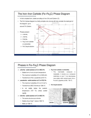
  • 1. 1 School of Mechanical Engineering, VIT - Vellore • In their simplest form, steels are alloys of Iron (Fe) and Carbon (C). • The Fe-C phase diagram is a fairly complex one, but we will only consider the steel part of the diagram, up to around 7% Carbon. The Iron–Iron Carbide (Fe–Fe3C) Phase Diagram 1 • Phases present  α-ferrite,  γ-ferrite,  δ-ferrite,  Fe3C (iron carbide or cementite)  Fe-C liquid solution School of Mechanical Engineering, VIT - Vellore  α-ferrite - solid solution of C in BCC Fe • Stable form of iron at room temperature. • The maximum solubility of C is 0.022 wt% • Transforms to FCC γ-austenite at 912 °C  γ-austenite - solid solution of C in FCC Fe • The maximum solubility of C is 2.14 wt %. • Transforms to BCC δ-ferrite at 1395 °C • Is not stable below the eutectic temperature (727 °C) unless cooled rapidly  δ-ferrite - solid solution of C in BCC Fe • The same structure as α-ferrite • Stable only at high T, above 1394 °C • Melts at 1538 °C Phases in Fe–Fe3C Phase Diagram 2  Fe3C (iron carbide or cementite) • This intermetallic compound is metastable, it remains as a compound indefinitely at room T, but decomposes (very slowly, within several years) into α- Fe and C (graphite) at 650 - 700 °C  Fe-C liquid solution α-ferrite austenite
  • 2. 2 School of Mechanical Engineering, VIT - Vellore • Pure iron when heated experiences two changes in crystal structure before it melts. • At room temperature the stable form, ferrite (α iron) has a BCC crystal structure. • Ferrite experiences a polymorphic transformation to FCC austenite (γ iron) at 912 ˚C (1674 ˚F). • At 1394˚C (2541˚F) austenite reverts back to BCC phase δ ferrite and melts at 1538˚C (2800˚F). • Iron carbide (cementite or Fe3C) an intermediate compound is formed at 6.7 wt% C. • Typically, all steels and cast irons have carbon contents less than 6.7 wt% C. • Carbon is an interstitial impurity in iron and forms a solid solution with the α, β, γ phases. Changes in Crystal Structure 3 School of Mechanical Engineering, VIT - Vellore • C is an interstitial impurity in Fe. It forms a solid solution with α, β, γ phases of iron • Maximum solubility in BCC α-ferrite is limited (max. 0.022 wt% at 727 °C) – which can be explained by the shape and size of the BCC interstitial positions, which make it difficult to accommodate the carbon atoms. BCC has relatively small interstitial positions. Even though present in relatively low concentrations, carbon significantly influences the mechanical properties of ferrite • Maximum solubility in FCC austenite is 2.14 wt% at 1147 °C - FCC has larger interstitial positions • Mechanical properties: Cementite is very hard and brittle - can strengthen steels. Mechanical properties also depend on the microstructure, that is, how ferrite and cementite are mixed. • Magnetic properties: α -ferrite is magnetic below 768 °C, austenite is non-magnetic A few comments on Fe–Fe3C system 4
  • 3. 3 School of Mechanical Engineering, VIT - Vellore • Three types of ferrous alloys: – Iron: • less than 0.008 wt % C in α−ferrite at room T – Steels: • 0.008 - 2.14 wt % C (usually < 1 wt % ); • α-ferrite + Fe3C at room T – Cast iron: • 2.14 - 6.7 wt % (usually < 4.5 wt %) Classification - Types of ferrous alloys 5 School of Mechanical Engineering, VIT - Vellore • In binary phase diagrams, a horizontal line always indicates an invariant reaction. • Three invariant reactions are present in Iron–Iron Carbide (Fe–Fe3C) Phase Diagram. 1. Peritectic reaction 2. Eutectic reaction 3. Eutectoid reaction Invariant Reactions in Fe–Fe3C System 6 1493 °C 1150 °C 727 °C γ δ
  • 4. 4 School of Mechanical Engineering, VIT - Vellore Peritectic, involves the following phase transformation. L(0.53% C) + δ (BCC Ferrite of 0.1% C) → γ (FCC Austenite of 0.18% C) • The maximum solubility of carbon in BCC δ-iron is 0.1% (point M) whereas in FCC γ-iron, it is greater. The presence of carbon influences the allotropic changes. As carbon is increased or added to the iron, the temperature increases from 1400ºC to 1493ºC at 0.1% carbon. Peritectic reaction - Fe–Fe3C System 7 M N P- B School of Mechanical Engineering, VIT - Vellore Consider the portion NMPB in Peritectic Reaction • On cooling, the portion NM represents the beginning of the crystal structure change from BCC δ iron to FCC γ iron for alloys containing less than 0.1% carbon. • Line MP represents the beginning of crystal structure change by means of peritectic reaction for the alloys between 0.1 & 0.18% Carbon. • Line NP represents the end of crystal structure change for alloys containing less than 0.18% C. • Portion PB represents the end of crystal structure by means of peritectic reaction for the alloys between 0.18- 0.5% carbon. Here the reaction takes place isothermally (i.e.) at constant temperature. • At the peritectic reaction point, liquid of 0.53% C combines with δ ferrite of 0.1% C to form FCC γ austenite of 0.18% C Peritectic reaction - Fe–Fe3C System 8 M N P- B
  • 5. 5 School of Mechanical Engineering, VIT - Vellore • Eutectic Point is given by point E (refer fig.2) exists at 4.3% Carbon and at the temperature of 1147°C. • Horizontal line represents the eutectic temperature line and whenever an alloy crosses the line must undergo the eutectic reaction • Any liquid that is present when this line is reached must solidify now into very fine intimate mixture of two phases namely austenite (γ) and cementite (Fe3C). • The eutectic mixture has been given with the name LEDEBURITE and the equation is given as Eutectic reaction - Fe–Fe3C System 9 L (4.3% C) (FCC) 2.14% C 6.67%C • The eutectic mixture is not usually seen in the microscope because the austenite is not stable at room temperatures and must undergo another reaction during cooling School of Mechanical Engineering, VIT - Vellore • An alloy of eutectoid composition (0.76 wt% C) as it is cooled from a temperature within the phase region, say, 800 °C—that is, beginning at point a and moving down the vertical line xx`. • Initially, the alloy is composed entirely of the austenite phase having a composition of 0.76 wt% C (Figure a). As the alloy is cooled, no changes will occur until the eutectoid temperature (727 °C) is reached. Upon crossing this temperature to point b, the austenite transforms to α and Fe3C) . • This microstructure, represented schematically in point b, is called pearlite (alternating layers or lamellae of α and Fe3C. Development of Microstructure - Fe–Fe3C System 10
  • 6. 6 School of Mechanical Engineering, VIT - Vellore • Formation of pearlite structure – Nucleating at γ grain boundary, – growth by diffusion of C to achieve the compositions of α and Fe3C (with structural changes) – α lamellae much thick ( relative layer thickness is approximately 8 to 1) Pearlite 11 Redistribution of carbon by diffusion • Austenite – 0.76 wt% C; • Ferrite - 0.022 wt% C • Cementite - 6.70 wt% C upper-critical- temperature line School of Mechanical Engineering, VIT - Vellore • Composition C0 to the left of the eutectoid, between 0.022 and 0.76 wt% C; is termed a hypoeutectoid (less than eutectoid) alloy. • At about 875°C, point c, the microstructure will consist entirely of grains of the γ phase (Fig c) • Cooling to point d, at about 775°C, both α phase and γ phase coexist (Fig d). • Cooling from point d to e, just above the eutectoid but still in the α + γ region, will produce an increased fraction of the α phase and a microstructure similar to fig e, the particles will have grown larger. • As the temperature is lowered just below the eutectoid, to point f, all the phase that was present at temperature Te (and having the eutectoid composition) will transform to pearlite, Hypoeutectoid Alloys 12
  • 7. 7 School of Mechanical Engineering, VIT - Vellore • In the austenite range, it is a uniform interstitial solid solution. Upon slow cooling, nothing happens until the line MO is crossed at point d. This MO line is known as the upper-critical-temperature line on the hypoeutectoid side. Hypoeutectoid Alloys 13 • At d, ferrite must begin to form at the austenite grain boundaries. Since ferrite can dissolve very little carbon, in those areas that are changing to ferrite the carbon must come out of solution before the atoms rearrange themselves to BCC • The carbon which comes out of solution is dissolved in the remaining austenite, so that, as cooling progresses and the amount of ferrite increases, the remaining austenite becomes richer in carbon. • Its carbon content is gradually moving down and to the right along the MO line. Finally, the line NO is reached at point f. School of Mechanical Engineering, VIT - Vellore • The ferrite phase will be present both in the pearlite and also as the phase that formed while cooling through the α and γ phase region. • The ferrite that is present in the pearlite is called eutectoid ferrite, whereas the other, that formed above Te, is termed proeutectoid ferrite (meaning “pre- or before eutectoid”) Hypoeutectoid Alloys 14
  • 8. 8 School of Mechanical Engineering, VIT - Vellore • Compositions to the right of eutectoid (0.76 - 2.14 wt % C) hypereutectoid (more than eutectoid -Greek) alloys. γ → γ + Fe3C → α + Fe3C • Hypereutectoid alloys contain proeutectoid cementite (formed above the eutectoid temperature) plus pearlite that contain eutectoid ferrite and cementite. Hypereutectoid Alloys 15 School of Mechanical Engineering, VIT - Vellore • In the austenite range, this alloy consists of a uniform FCC solid solution with each grain containing 1.0 percent carbon dissolved interstitially. Hypereutectoid Alloys 16 • Upon slow cooling, nothing happens until the line OP is crossed at point h. This line is called upper-critical- temperature line on the hypereutectoid side. • The OP line shows the maximum amount of carbon that can be dissolved in austenite as a function of temperature. • Above the OP line, austenite is an unsaturated solid solution. • At h, the austenite is saturated in carbon. As the temperature is decreased, the carbon content of the austenite, that is, the maximum amount of carbon that can be dissolved in austenite, moves down along OP line towards point O. • Therefore, as the temperature decreases from h to i, the excess carbon above the amount required to saturate austenite is precipitated as cementite primarily along the grain boundaries. • Finally, the eutectoid line is reached at i. This line is called the lower-critical-temperature line on the hypereutectoid side
  • 9. 9 School of Mechanical Engineering, VIT - Vellore Development of Microstructure - Fe–Fe3C System 17 Eutectoid steel α+Fe3C Pearlite Hypoeutectoid steel α+Fe3C Pearlite + proeutectoid ferrite Hypereutectoid steel α+Fe3C Pearlite + proeutectoid cementite School of Mechanical Engineering, VIT - Vellore How to calculate the relative amounts of proeutectoid phase (α or Fe3C) and pearlite? • Application of the lever rule with tie line, that extends from the eutectoid composition (0.76 wt% C) – to α – (α + Fe3C) boundary (0.022 wt% C) for hypoeutectoid alloys and – to (α + Fe3C) – Fe3C boundary (6.7 wt% C) for hypereutectoid alloys. Development of Microstructure - Fe–Fe3C System 18 • Fraction of α phase is determined by application of the lever rule across the entire (α + Fe3C) phase.
  • 10. 10 School of Mechanical Engineering, VIT - Vellore Example for hypoeutectoid alloy with composition • Fraction of pearlite: • Fraction of proeutectoid ferrite α’: Development of Microstructure - Fe–Fe3C System 19 74 . 0 022 . 0 022 . 0 76 . 0 022 . 0 ' 0 ' 0 − = − − = + = C C U T T WP 74 . 0 76 . 0 022 . 0 76 . 0 76 . 0 ' 0 ' 0 ' C C U T U W − = − − = + = α ' 0 C School of Mechanical Engineering, VIT - Vellore Example for hypereutectoid alloy with composition • Fraction of pearlite: • Fraction of proeutectoid cementite: Development of Microstructure - Fe–Fe3C System 20 94 . 5 70 . 6 76 . 0 70 . 6 70 . 6 ' 1 ' 1 C C X V X WP − = − − = + = 94 . 5 76 . 0 76 . 0 70 . 6 76 . 0 ' 1 ' 1 3 − = − − = + = C C X V V W C Fe ' 1 C
  • 11. 11 School of Mechanical Engineering, VIT - Vellore Determination of relative amount of ferrite, cementite and pearlite 21 School of Mechanical Engineering, VIT - Vellore Determination of relative amount of ferrite, cementite and pearlite 22
  • 12. 12 School of Mechanical Engineering, VIT - Vellore Determination of relative amount of ferrite, cementite and pearlite 23 School of Mechanical Engineering, VIT - Vellore • The microstructural development of iron–carbon alloys it has been assumed that, upon cooling, conditions of metastable equilibrium have been continuously maintained; that is, sufficient time has been allowed at each new temperature for any necessary adjustment in phase compositions and relative amounts as predicted from the Fe–Fe3C phase diagram. Influence of other Alloying Elements - Teutectoid changes 24 Fig 1: The dependence of eutectoid temperature on alloy concentration for several alloying elements in steel • These cooling rates are impractically slow and really unnecessary; in fact, on many occasions nonequilibrium conditions are desirable. Two nonequilibrium effects of practical importance are 1. the occurrence of phase changes or transformations at temperatures other than those predicted by phase boundary lines on the phase diagram, and 2. the existence at room temperature of non- equilibrium phases that do not appear on the phase diagram.
  • 13. 13 School of Mechanical Engineering, VIT - Vellore • Additions of other alloying elements (Cr, Ni,Ti, etc.) bring about rather dramatic changes in the binary iron–iron carbide phase diagram, Fig 1. The extent of these alterations of the positions of phase boundaries and the shapes of the phase fields depends on the particular alloying element and its concentration. Influence of other Alloying Elements - Ceutectoid changes 25 Fig 2: The dependence of eutectoid composition (wt% C) on alloy concentration for several alloying elements in steel. • One of the important changes is the shift in position of the eutectoid with respect to temperature and to carbon concentration. Fig 1 and 2, which plot the eutectoid temperature and eutectoid composition (in wt% C) as a function of concentration for several other alloying elements. Thus, other alloy additions alter not only the temperature of the eutectoid reaction but also the relative fractions of pearlite and the proeutectoid phase that form. Steels are normally alloyed for other reasons, however- usually either to improve their corrosion resistance or to render them amenable to heat treatment School of Mechanical Engineering, VIT - Vellore • Cementite (Fe3C) – Contains 6.67% wt of Carbon – Hard, Brittle Interstitial compound – Tensile strength – 5000 psi approx. and has high compressive strength – Crystal structure is orthorhombic • Austenite (γ) – Interstitial solid solution of carbon – Has FCC crystal structure – can accommodate more carbon than ferrite – Max. solubility of carbon in this phase is 2% at 1148 °C and lowers to 0.8% at 723 °C – Tensile strength – 1,50,000 psi; Elongation – 2% in 2” – Hardness – 40 HRC – Not normally stable at room temperatures Definitions of structures 26
  • 14. 14 School of Mechanical Engineering, VIT - Vellore • α - Ferrite – Interstitial solid solution of carbon in BCC crystal lattice – As indicated in the Iron- Iron carbide equilibrium diagram, carbon is only slightly soluble in -Ferrite and has the solubility of 0.025% at 723 °C – Softest structure that appears on the diagram – Average Props : TS – 40000 psi, Hardness – 90BHN • Pearlite (α + Fe3C) – Eutectoid mixture containing 0.8% Carbon and is formed at 723 °C on very slow cooling – Microstructure has very fine plate like / lamellar structure – Average Props : TS – 120000 psi, Hardness – 20HRC Definitions of structures 27