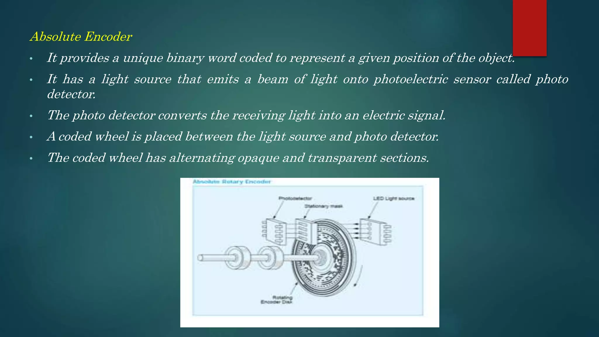
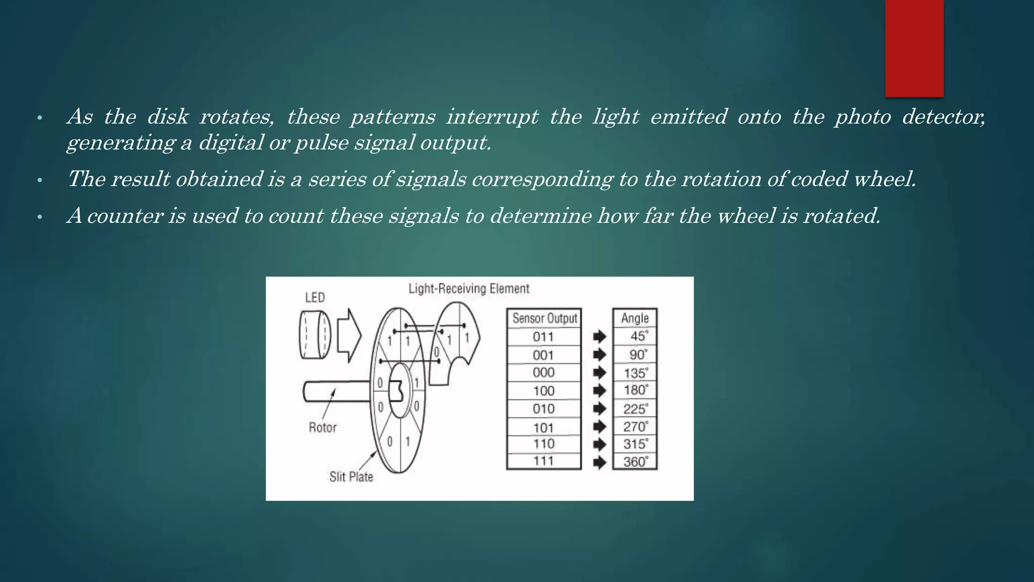
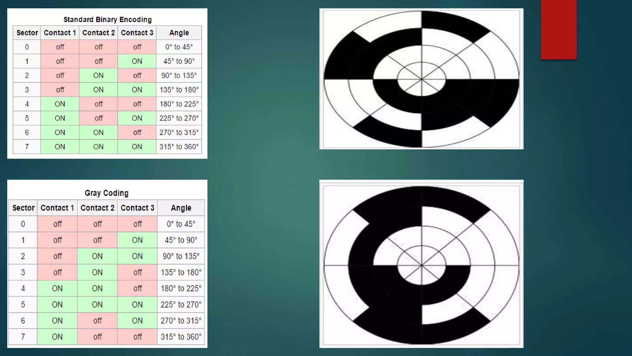
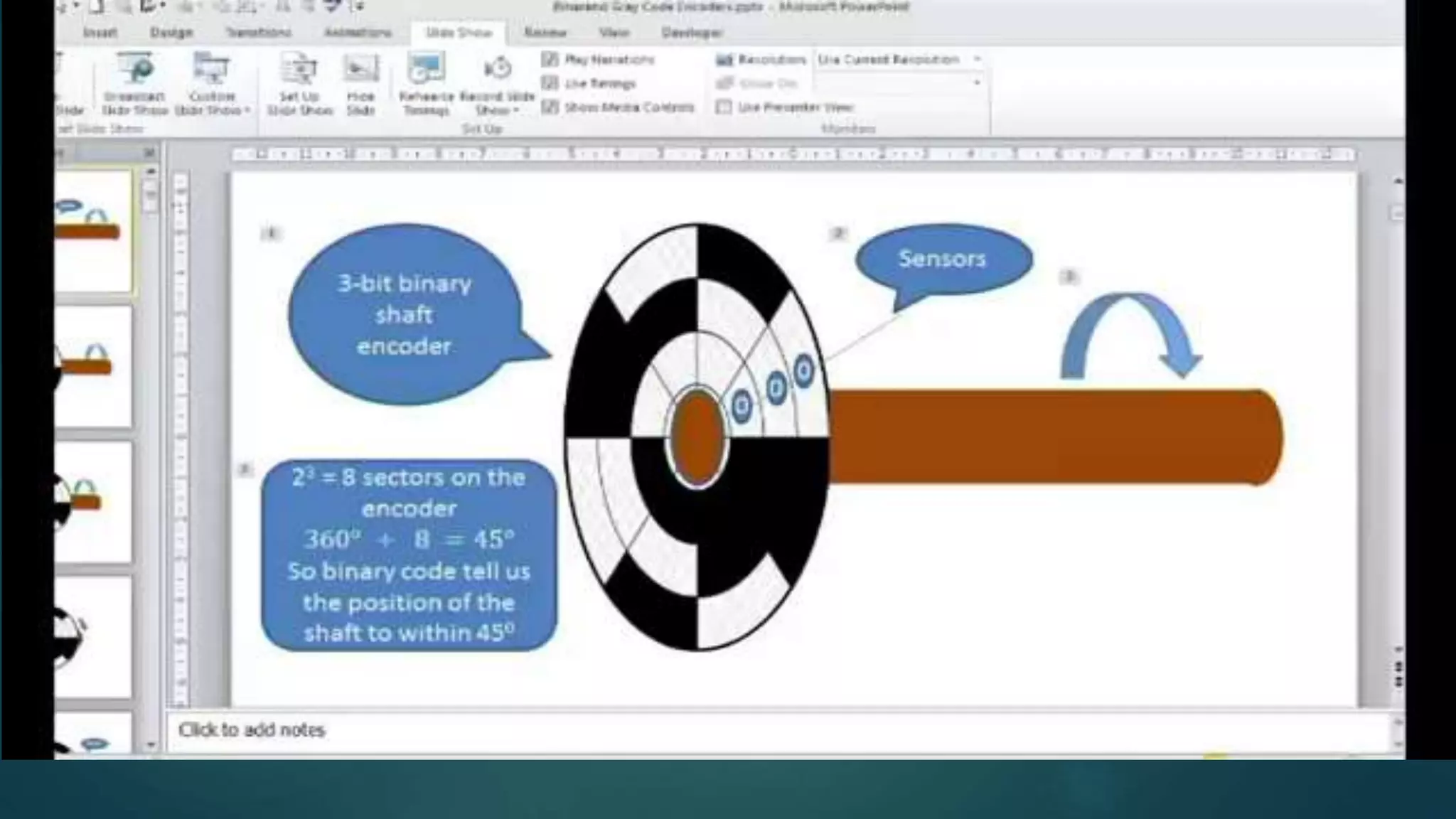
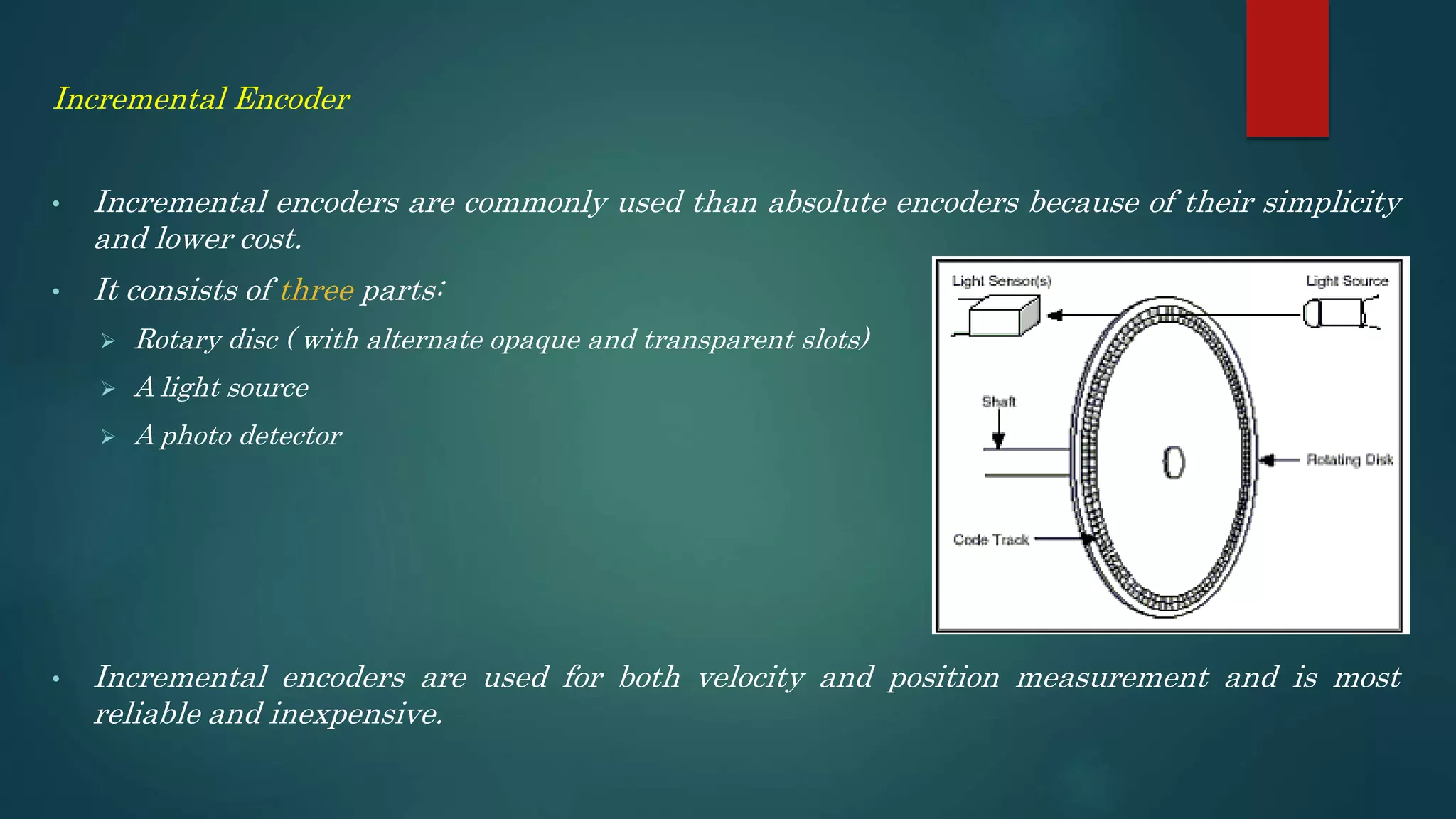
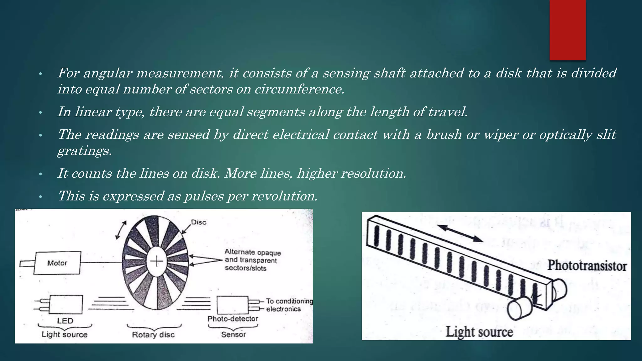
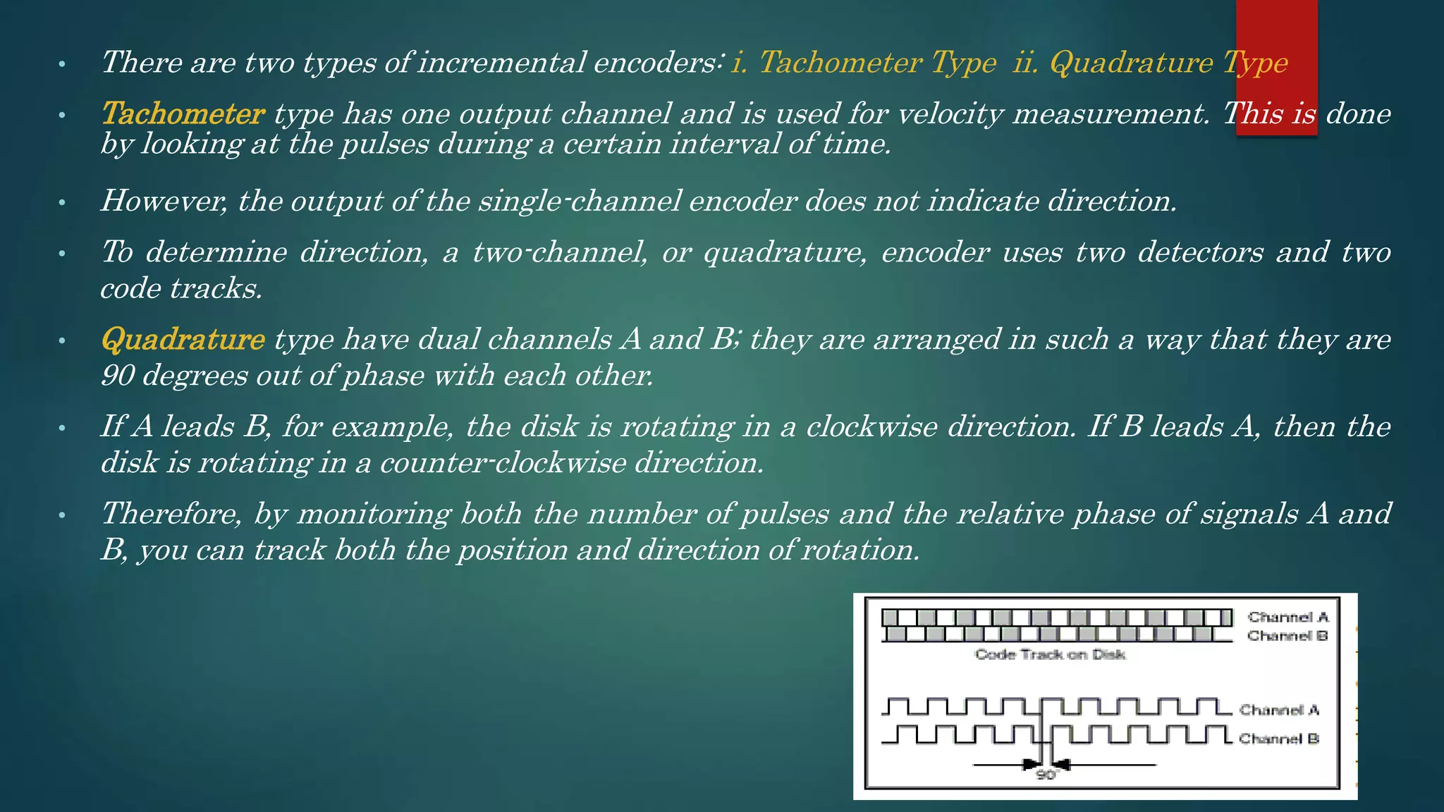
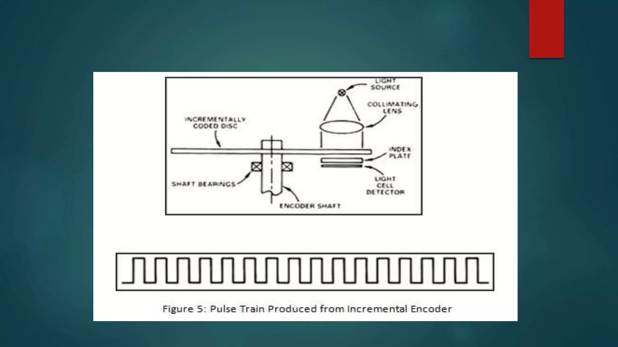
OVERVIEW
• Tachogenerator
• Optical Encoder :
i. Incremental
ii. Absolute
Tachogenerator
• An electromechanical generator is a device capable of producing electrical power from
mechanical energy, usually the turning of a shaft.
• They are the measurement devices for measuring the shaft speed in mechanical equipment.
• One of the more common voltage signal ranges used with tachogenerators is 0 to 10 volts.
• Tachogenerators are frequently used to measure the speeds of electric motors, engines, and
the equipment they power: conveyor belts, machine tools, mixers, fans, etc.
Principle of Operation
The major principle for tachogenerator is that the relative motion between a magnetic field
and a conductor results the voltage in that conductor.
There are mainly two types of tachogenerator:
• A.C. Tachogenerator
• D.C. Tachogenerator
DC Tachogenrator
Construction
• An Armature is rotating type & this magnet is fixed type.
• Armature is coupled to a machine whose velocity is to be measured.
• It consists of commutator and brushes is connected to armature.
• Output is connected to Moving Coil (MC) type Voltmeter.
Operation
• When the armature is stationary there is no relative motion between the magnetic field and
the armature winding.
• Hence the output voltage is Zero
• As the armature speed increases the relative motion also increases.
• The output voltage is induced in the armature winding.
• The magnitude of this voltage is proportional to the speed of armature.
• A commutator and brush are connected in the armature to give the DC output voltage.
• This output voltage is measured with the help of moving coil voltmeter calibrated in terms of
speed.
Optical Encoders
• An optical encoder is an electromechanical device which has an electrical output in digital
form proportional to the angular position of the input shaft.
• It is used to measure rotational movement precisely.
• Information obtainable from an optical encoder includes direction, distance, velocity and
position.
There are two types of encoders:
1. Absolute Encoders
2. Incremental Encoders
Absolute Encoder
• It provides a unique binary word coded to represent a given position of the object.
• It has a light source that emits a beam of light onto photoelectric sensor called photo
detector.
• The photo detector converts the receiving light into an electric signal.
• A coded wheel is placed between the light source and photo detector.
• The coded wheel has alternating opaque and transparent sections.
• As the disk rotates, these patterns interrupt the light emitted onto the photo detector,
generating a digital or pulse signal output.
• The result obtained is a series of signals corresponding to the rotation of coded wheel.
• A counter is used to count these signals to determine how far the wheel is rotated.
Encoding Techniques
There are two types of encoding techniques:
• Standard Binary Encoding
• Gray Encoding
Incremental Encoder
• Incremental encoders are commonly used than absolute encoders because of their simplicity
and lower cost.
• It consists of three parts:
 Rotary disc ( with alternate opaque and transparent slots)
 A light source
 A photo detector
• Incremental encoders are used for both velocity and position measurement and is most
reliable and inexpensive.
• For angular measurement, it consists of a sensing shaft attached to a disk that is divided
into equal number of sectors on circumference.
• In linear type, there are equal segments along the length of travel.
• The readings are sensed by direct electrical contact with a brush or wiper or optically slit
gratings.
• It counts the lines on disk. More lines, higher resolution.
• This is expressed as pulses per revolution.
• There are two types of incremental encoders: i. Tachometer Type ii. Quadrature Type
• Tachometer type has one output channel and is used for velocity measurement. This is done
by looking at the pulses during a certain interval of time.
• However, the output of the single-channel encoder does not indicate direction.
• To determine direction, a two-channel, or quadrature, encoder uses two detectors and two
code tracks.
• Quadrature type have dual channels A and B; they are arranged in such a way that they are
90 degrees out of phase with each other.
• If A leads B, for example, the disk is rotating in a clockwise direction. If B leads A, then the
disk is rotating in a counter-clockwise direction.
• Therefore, by monitoring both the number of pulses and the relative phase of signals A and
B, you can track both the position and direction of rotation.
Robot Sensing System - 2

Robot Sensing System - 2

  • 1.
    OVERVIEW • Tachogenerator • OpticalEncoder : i. Incremental ii. Absolute
  • 2.
    Tachogenerator • An electromechanicalgenerator is a device capable of producing electrical power from mechanical energy, usually the turning of a shaft. • They are the measurement devices for measuring the shaft speed in mechanical equipment. • One of the more common voltage signal ranges used with tachogenerators is 0 to 10 volts. • Tachogenerators are frequently used to measure the speeds of electric motors, engines, and the equipment they power: conveyor belts, machine tools, mixers, fans, etc.
  • 3.
    Principle of Operation Themajor principle for tachogenerator is that the relative motion between a magnetic field and a conductor results the voltage in that conductor. There are mainly two types of tachogenerator: • A.C. Tachogenerator • D.C. Tachogenerator
  • 4.
  • 5.
    Construction • An Armatureis rotating type & this magnet is fixed type. • Armature is coupled to a machine whose velocity is to be measured. • It consists of commutator and brushes is connected to armature. • Output is connected to Moving Coil (MC) type Voltmeter. Operation • When the armature is stationary there is no relative motion between the magnetic field and the armature winding. • Hence the output voltage is Zero • As the armature speed increases the relative motion also increases. • The output voltage is induced in the armature winding. • The magnitude of this voltage is proportional to the speed of armature. • A commutator and brush are connected in the armature to give the DC output voltage. • This output voltage is measured with the help of moving coil voltmeter calibrated in terms of speed.
  • 6.
    Optical Encoders • Anoptical encoder is an electromechanical device which has an electrical output in digital form proportional to the angular position of the input shaft. • It is used to measure rotational movement precisely. • Information obtainable from an optical encoder includes direction, distance, velocity and position. There are two types of encoders: 1. Absolute Encoders 2. Incremental Encoders
  • 7.
    Absolute Encoder • Itprovides a unique binary word coded to represent a given position of the object. • It has a light source that emits a beam of light onto photoelectric sensor called photo detector. • The photo detector converts the receiving light into an electric signal. • A coded wheel is placed between the light source and photo detector. • The coded wheel has alternating opaque and transparent sections.
  • 8.
    • As thedisk rotates, these patterns interrupt the light emitted onto the photo detector, generating a digital or pulse signal output. • The result obtained is a series of signals corresponding to the rotation of coded wheel. • A counter is used to count these signals to determine how far the wheel is rotated.
  • 9.
    Encoding Techniques There aretwo types of encoding techniques: • Standard Binary Encoding • Gray Encoding
  • 12.
    Incremental Encoder • Incrementalencoders are commonly used than absolute encoders because of their simplicity and lower cost. • It consists of three parts:  Rotary disc ( with alternate opaque and transparent slots)  A light source  A photo detector • Incremental encoders are used for both velocity and position measurement and is most reliable and inexpensive.
  • 13.
    • For angularmeasurement, it consists of a sensing shaft attached to a disk that is divided into equal number of sectors on circumference. • In linear type, there are equal segments along the length of travel. • The readings are sensed by direct electrical contact with a brush or wiper or optically slit gratings. • It counts the lines on disk. More lines, higher resolution. • This is expressed as pulses per revolution.
  • 14.
    • There aretwo types of incremental encoders: i. Tachometer Type ii. Quadrature Type • Tachometer type has one output channel and is used for velocity measurement. This is done by looking at the pulses during a certain interval of time. • However, the output of the single-channel encoder does not indicate direction. • To determine direction, a two-channel, or quadrature, encoder uses two detectors and two code tracks. • Quadrature type have dual channels A and B; they are arranged in such a way that they are 90 degrees out of phase with each other. • If A leads B, for example, the disk is rotating in a clockwise direction. If B leads A, then the disk is rotating in a counter-clockwise direction. • Therefore, by monitoring both the number of pulses and the relative phase of signals A and B, you can track both the position and direction of rotation.