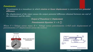
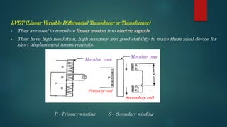
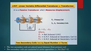
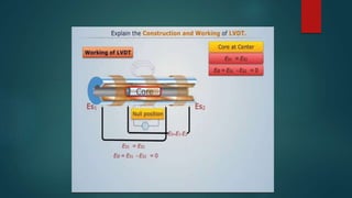
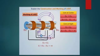
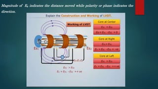
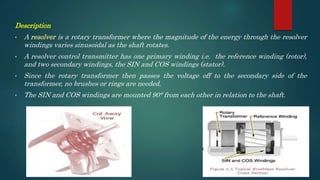
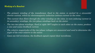
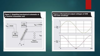
OVERVIEW
• Potentiometer
• LVDT
• Resolver
Potentiometer
• Potentiometer is a transducer in which rotation or linear displacement is converted into potential
difference.
• The displacement of the wiper causes the output potential difference obtained between one end of
the resistance and the slider.
Output of Transducer ∝ Displacement
Potentiometric Equation: 𝑽 = 𝑬. (
𝒅
𝑳
)
Where V = Voltage across wiper, E = Voltage across potentiometer, L=full scale displacement of
potentiometer, d = displacement across the resistor.
Rotational Potentiometer Linear Potentiometer
LVDT (Linear Variable Differential Transducer or Transformer)
• They are used to translate linear motion into electric signals.
• They have high resolution, high accuracy and good stability to make them ideal device for
short displacement measurements.
Movable core
Movable core
Primary coil
Secondary coil
P – Primary winding S – Secondary winding
P₁S₁ S₂
P₁ - Primary Coil
S₁ , S₂ - Secondary Coils
AC Source
• The two secondary coils are placed equal distance from primary coil.
• Two secondary coils are connected in series opposition i.e. Net Emf = 0.
Working of LVDT
• There are three positions of core based on which the LVDT works.
• This also determines the magnitude and direction of emf induced.
i. Core at center
ii. Core at right corner
iii. Core at left corner
Magnitude of E₀ indicates the distance moved while polarity or phase indicates the
direction.
Resolver
• A resolver is used for measuring degrees of rotation.
• Operating principle is that a charged rotating shaft will induce voltage on stationary coils.
Description
• A resolver is a rotary transformer where the magnitude of the energy through the resolver
windings varies sinusoidal as the shaft rotates.
• A resolver control transmitter has one primary winding i.e. the reference winding (rotor),
and two secondary windings, the SIN and COS windings (stator).
• Since the rotary transformer then passes the voltage off to the secondary side of the
transformer, no brushes or rings are needed.
• The SIN and COS windings are mounted 90° from each other in relation to the shaft.
Working of a Resolver
• The primary winding of the transformer, fixed to the stator, is excited by a sinusoidal
electric current, which by electromagnetic induction induces current in the rotor.
• This current then flows through the other winding on the rotor, in turn inducing current in
its secondary windings, the two-phase windings back on the stator.
• The two two-phase windings, fixed at right (90°) angles to each other on the stator, produce
a sine and cosine feedback current.
• The relative magnitudes of the two-phase voltages are measured and used to determine the
angle of the rotor relative to the stator.
• Upon one full revolution, the feedback signals repeat their waveforms.
Robot Sensing Systems - 1

Robot Sensing Systems - 1

  • 1.
  • 2.
    Potentiometer • Potentiometer isa transducer in which rotation or linear displacement is converted into potential difference. • The displacement of the wiper causes the output potential difference obtained between one end of the resistance and the slider. Output of Transducer ∝ Displacement Potentiometric Equation: 𝑽 = 𝑬. ( 𝒅 𝑳 ) Where V = Voltage across wiper, E = Voltage across potentiometer, L=full scale displacement of potentiometer, d = displacement across the resistor. Rotational Potentiometer Linear Potentiometer
  • 4.
    LVDT (Linear VariableDifferential Transducer or Transformer) • They are used to translate linear motion into electric signals. • They have high resolution, high accuracy and good stability to make them ideal device for short displacement measurements. Movable core Movable core Primary coil Secondary coil P – Primary winding S – Secondary winding
  • 5.
    P₁S₁ S₂ P₁ -Primary Coil S₁ , S₂ - Secondary Coils AC Source • The two secondary coils are placed equal distance from primary coil. • Two secondary coils are connected in series opposition i.e. Net Emf = 0.
  • 6.
    Working of LVDT •There are three positions of core based on which the LVDT works. • This also determines the magnitude and direction of emf induced. i. Core at center ii. Core at right corner iii. Core at left corner
  • 9.
    Magnitude of E₀indicates the distance moved while polarity or phase indicates the direction.
  • 11.
    Resolver • A resolveris used for measuring degrees of rotation. • Operating principle is that a charged rotating shaft will induce voltage on stationary coils.
  • 12.
    Description • A resolveris a rotary transformer where the magnitude of the energy through the resolver windings varies sinusoidal as the shaft rotates. • A resolver control transmitter has one primary winding i.e. the reference winding (rotor), and two secondary windings, the SIN and COS windings (stator). • Since the rotary transformer then passes the voltage off to the secondary side of the transformer, no brushes or rings are needed. • The SIN and COS windings are mounted 90° from each other in relation to the shaft.
  • 13.
    Working of aResolver • The primary winding of the transformer, fixed to the stator, is excited by a sinusoidal electric current, which by electromagnetic induction induces current in the rotor. • This current then flows through the other winding on the rotor, in turn inducing current in its secondary windings, the two-phase windings back on the stator. • The two two-phase windings, fixed at right (90°) angles to each other on the stator, produce a sine and cosine feedback current. • The relative magnitudes of the two-phase voltages are measured and used to determine the angle of the rotor relative to the stator. • Upon one full revolution, the feedback signals repeat their waveforms.