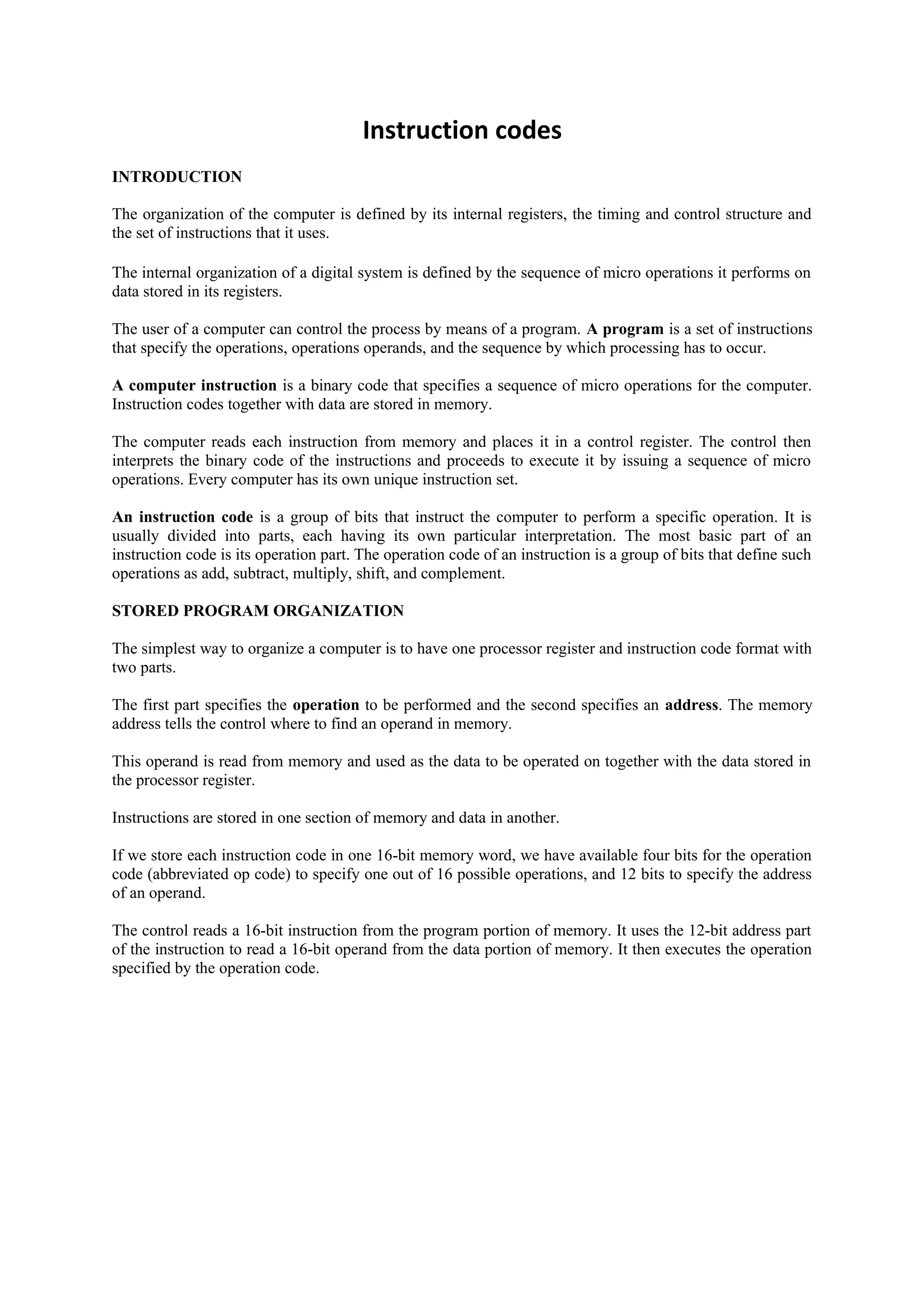
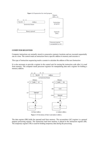
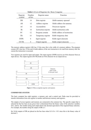
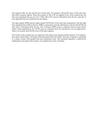
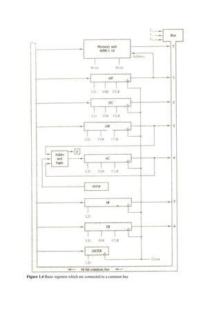
In these slides the registration organization and stack organization have discussed in detail. Stack organization is discussed with the aid of animation to let the user understand it in a better and easy way.
Memory reference instructions used in computer architecture is well demonstrated with examples. It will probably help you understand each referencing instructions.
Instruction FormatMachine instruction has an opcode and zero or m.pdfpritikulkarni20
Instruction Format:
Machine instruction has an opcode and zero or more operands. Architectures are differentiated
from one another by the number of bits allowed per instruction (16, 32, and 64 are the most
common), by the number of operands allowed per instruction, and by the types of instructions
and data each can process. More specifically, instruction sets are differentiated by the following
features:
• Operand storage in the CPU (data can be stored in a stack structure or in registers) • Number of
explicit operands per instruction (zero, one, two, and three being the most common)
• Operand location (instructions can be classified as register-to-register, register-to-memory or
memory-to-memory, which simply refer to the combinations of operands allowed per
instruction)
• Operations (including not only types of operations but also which instructions can access
memory and which cannot) • Type and size of operands (operands can be addresses, numbers, or
even characters)
The following are some common instruction formats:
• OPCODE only (zero addresses)
• OPCODE + 1 Address (usually a memory address)
• OPCODE + 2 Addresses (usually registers, or one register and one memory address)
• OPCODE + 3 Addresses (usually registers, or combinations of registers and memory)
Instruction Length:
The traditional method for describing a computer architecture is to specify the maximum number
of operands, or addresses, contained in each instruction. This has a direct impact on the length of
the instruction itself. Instructions on current architectures can be formatted in two ways: • Fixed
length-Wastes space but is fast and results in better performance when instruction-level
pipelining is used, as we see in Section 5.5. • Variable length-More complex to decode but saves
storage space.
Memory organization affects instruction format. If memory has, for example, 16 or 32-bit words
and is not byte-addressable, it is difficult to access a single character. For this reason, even
machines that have 16-, 32-, or 64-bit words are often byteaddressable, meaning every byte has a
unique address even though words are longer than 1 byte.
COMMON BUS Structure:
The basic computer has eight registers, a memory unit, and a control unit. Paths must be
provided to transfer information from one register to another and between memory and registers.
The number of wires will be excessive if connections are made between the outputs of each
register and the inputs of the other registers. A more efficient scheme for transferring
information in a system with many registers is to use a common bus. It is known that how to
construct a bus PC AR 11 0 11 0 15 0 15 0 7 0 7 0 IR TR INPR AC DR 15 0 15 0 Memory 4096
words 16 bits per word 6 system using multiplexers or three-state buffer gates. The outputs of
seven registers and memory are connected to the common bus. The specific output that is
selected for the bus lines at any given time is determined from the binary value of the selection
vari.
based on stored program design
processor system
CPU
memory
input/output system
input/output devices
secondary storage
manages the instruction-execution cycle
FETCH – DECODE – EXECUTE
coordinates the activities of other devices
This slide provide the introduction to the computer , instruction formats and their execution, Common Bus System , Instruction Cycle, Hardwired Control Unit and I/O operation and handling of interrupt
The design and creation of a fully functional computer through the use of a Field Programmable Gate Array. The FPGA was designed through the hardware description language VHDL. Once the entire computer was interfaced, a video game was programmed through the use of assembly language. The computer was able to drive a monitor, and have a keyboard for human interrupts.
June 3, 2024 Anti-Semitism Letter Sent to MIT President Kornbluth and MIT Cor...Levi Shapiro
Letter from the Congress of the United States regarding Anti-Semitism sent June 3rd to MIT President Sally Kornbluth, MIT Corp Chair, Mark Gorenberg
Dear Dr. Kornbluth and Mr. Gorenberg,
The US House of Representatives is deeply concerned by ongoing and pervasive acts of antisemitic
harassment and intimidation at the Massachusetts Institute of Technology (MIT). Failing to act decisively to ensure a safe learning environment for all students would be a grave dereliction of your responsibilities as President of MIT and Chair of the MIT Corporation.
This Congress will not stand idly by and allow an environment hostile to Jewish students to persist. The House believes that your institution is in violation of Title VI of the Civil Rights Act, and the inability or
unwillingness to rectify this violation through action requires accountability.
Postsecondary education is a unique opportunity for students to learn and have their ideas and beliefs challenged. However, universities receiving hundreds of millions of federal funds annually have denied
students that opportunity and have been hijacked to become venues for the promotion of terrorism, antisemitic harassment and intimidation, unlawful encampments, and in some cases, assaults and riots.
The House of Representatives will not countenance the use of federal funds to indoctrinate students into hateful, antisemitic, anti-American supporters of terrorism. Investigations into campus antisemitism by the Committee on Education and the Workforce and the Committee on Ways and Means have been expanded into a Congress-wide probe across all relevant jurisdictions to address this national crisis. The undersigned Committees will conduct oversight into the use of federal funds at MIT and its learning environment under authorities granted to each Committee.
• The Committee on Education and the Workforce has been investigating your institution since December 7, 2023. The Committee has broad jurisdiction over postsecondary education, including its compliance with Title VI of the Civil Rights Act, campus safety concerns over disruptions to the learning environment, and the awarding of federal student aid under the Higher Education Act.
• The Committee on Oversight and Accountability is investigating the sources of funding and other support flowing to groups espousing pro-Hamas propaganda and engaged in antisemitic harassment and intimidation of students. The Committee on Oversight and Accountability is the principal oversight committee of the US House of Representatives and has broad authority to investigate “any matter” at “any time” under House Rule X.
• The Committee on Ways and Means has been investigating several universities since November 15, 2023, when the Committee held a hearing entitled From Ivory Towers to Dark Corners: Investigating the Nexus Between Antisemitism, Tax-Exempt Universities, and Terror Financing. The Committee followed the hearing with letters to those institutions on January 10, 202
Normal Labour/ Stages of Labour/ Mechanism of LabourWasim Ak
Normal labor is also termed spontaneous labor, defined as the natural physiological process through which the fetus, placenta, and membranes are expelled from the uterus through the birth canal at term (37 to 42 weeks
A Strategic Approach: GenAI in EducationPeter Windle
Artificial Intelligence (AI) technologies such as Generative AI, Image Generators and Large Language Models have had a dramatic impact on teaching, learning and assessment over the past 18 months. The most immediate threat AI posed was to Academic Integrity with Higher Education Institutes (HEIs) focusing their efforts on combating the use of GenAI in assessment. Guidelines were developed for staff and students, policies put in place too. Innovative educators have forged paths in the use of Generative AI for teaching, learning and assessments leading to pockets of transformation springing up across HEIs, often with little or no top-down guidance, support or direction.
This Gasta posits a strategic approach to integrating AI into HEIs to prepare staff, students and the curriculum for an evolving world and workplace. We will highlight the advantages of working with these technologies beyond the realm of teaching, learning and assessment by considering prompt engineering skills, industry impact, curriculum changes, and the need for staff upskilling. In contrast, not engaging strategically with Generative AI poses risks, including falling behind peers, missed opportunities and failing to ensure our graduates remain employable. The rapid evolution of AI technologies necessitates a proactive and strategic approach if we are to remain relevant.
Unit 8 - Information and Communication Technology (Paper I).pdfThiyagu K
This slides describes the basic concepts of ICT, basics of Email, Emerging Technology and Digital Initiatives in Education. This presentations aligns with the UGC Paper I syllabus.
Chapter 3 - Islamic Banking Products and Services.pptx
Instruction codes
1. Instruction codes
INTRODUCTION
The organization of the computer is defined by its internal registers, the timing and control structure and
the set of instructions that it uses.
The internal organization of a digital system is defined by the sequence of micro operations it performs on
data stored in its registers.
The user of a computer can control the process by means of a program. A program is a set of instructions
that specify the operations, operations operands, and the sequence by which processing has to occur.
A computer instruction is a binary code that specifies a sequence of micro operations for the computer.
Instruction codes together with data are stored in memory.
The computer reads each instruction from memory and places it in a control register. The control then
interprets the binary code of the instructions and proceeds to execute it by issuing a sequence of micro
operations. Every computer has its own unique instruction set.
An instruction code is a group of bits that instruct the computer to perform a specific operation. It is
usually divided into parts, each having its own particular interpretation. The most basic part of an
instruction code is its operation part. The operation code of an instruction is a group of bits that define such
operations as add, subtract, multiply, shift, and complement.
STORED PROGRAM ORGANIZATION
The simplest way to organize a computer is to have one processor register and instruction code format with
two parts.
The first part specifies the operation to be performed and the second specifies an address. The memory
address tells the control where to find an operand in memory.
This operand is read from memory and used as the data to be operated on together with the data stored in
the processor register.
Instructions are stored in one section of memory and data in another.
If we store each instruction code in one 16-bit memory word, we have available four bits for the operation
code (abbreviated op code) to specify one out of 16 possible operations, and 12 bits to specify the address
of an operand.
The control reads a 16-bit instruction from the program portion of memory. It uses the 12-bit address part
of the instruction to read a 16-bit operand from the data portion of memory. It then executes the operation
specified by the operation code.
2. COMPUTER REGISTERS
Computer instructions are normally stored in consecutive memory locations and are executed sequentially
one at a time. The control reads an instruction from a specific address in memory and executes it.
This type of instruction sequencing needs a counter to calculate the address of the next Instruction
It is also necessary to provide a register in the control unit for storing the instruction code after it is read
from memory. The computer needs processor registers for manipulating data and a register for holding a
memory address.
The data register (DR) holds the operand read from memory. The accumulator (AC) register is a general
purpose processing register. The instruction read form memory is placed in the instruction register (IR).
The temporary register (TR) is used for holding temporary data during the processing.
3. The memory address register (AR) has 12 bits since this is the width of a memory address. The program
counter (PC) also has 12 bits and it holds address of the next instruction to be read from memory after the
current the instruction is executed.
Two registers are used for input and output. The input register (INPR) receives an 8-bit character from an
input device. The output register (OUTR) holds an 8-bit character for an output device.
COMMON BUS SYSTEM
The basic computer has eight registers, a memory unit, and a control unit. Paths must be provided to
transfer information from one register to another and between memory and registers.
The outputs of seven registers and memory are connected to the common bus. The specific output that is
selected for the bus lines at any given time is determined from the binary value of the selection variables
S2S1, and S0. The number along each output shows the decimal equivalent of the required binary selection.
For example, the number along the output of DR is 3.
the 16-bit outputs of DR are placed on the bus lines when S 2 S1 S0 = 011 since this is the binary value of
decimal 3.
4. Four registers, DR, AC, IR, and TR, have 16-bits each. Two registers, AR and PC, have 12 bits each since
they hold a memory address. When the contents of AR or PC are applied to the 16-bit common bus, the
four most significant bits are set to 0’s. When AR or PC receives information from the bus, only the 12
least significant bits are transferred into the register.
The input register INPR and the output register OUTR have 8 bits each and communicate with the eight
least significant bits (LSB) in the bus. INPR is connected to provide information to the bus but OUTR can
only receive information from the bus. This is because INPR receives a character from an input device
which is then transferred to AC. OUTR receives a character from AC and delivers it to an output device.
There is no transfer from OUTR to any of the other registers.
The 16 lines of the common bus are connected to the inputs of six registers and the memory. Five registers
have three control inputs: LD (load), INR (increment) and CLR (clear). This type of register is equivalent
to a binary counter with parallel load and synchronous clear. The increment operation is achieved by
enabling the count input of the counter. Two registers have only a LD input.