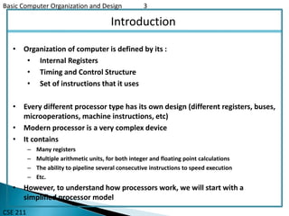
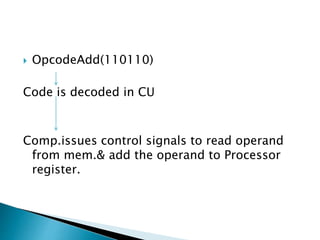
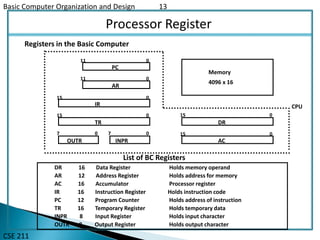
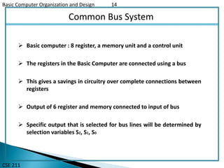
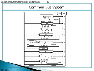
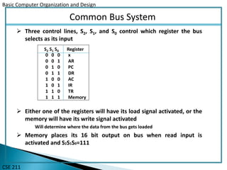
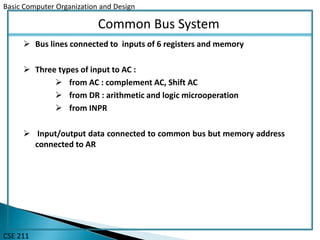
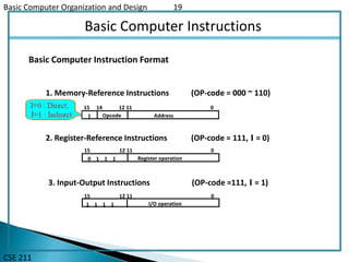
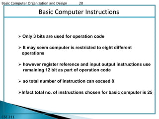
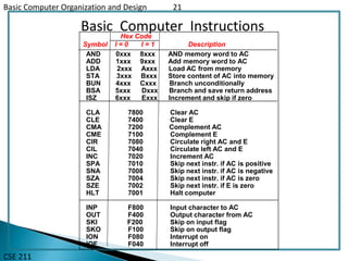
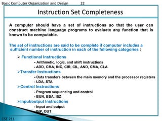
The document provides an overview of a course on basic computer organization and design. It describes the components of a basic computer including the processor, memory, registers, bus, and instruction set. The processor contains registers like the program counter, address register, data register, accumulator, and input/output registers. The memory can hold 4096 16-bit words. The instruction set includes memory reference, register reference, and input/output instructions that allow basic arithmetic, logic, branching, and I/O operations.
COMPUTER INSTRUCTIONS & TIMING & CONTROL.
This is very useful to undarstand the topic COMPUTER INSTRUCTIONS & TIMING & CONTROL in computer system architecture.
COMPUTER INSTRUCTIONS & TIMING & CONTROL.
This is very useful to undarstand the topic COMPUTER INSTRUCTIONS & TIMING & CONTROL in computer system architecture.
The Control Unit and the Arithmetic and Logic Unit constitute the Central Processing Unit
Data and instructions need to get into the system and results out
Input/output
Temporary storage of code and results is needed
Main memory
This slide deals with the Input-Output Channel of an IBM 370 computer. It includes three Block diagrams of the I-O channels as well as the Memory Unit with the Description of each and every diagrams.
based on stored program design
processor system
CPU
memory
input/output system
input/output devices
secondary storage
manages the instruction-execution cycle
FETCH – DECODE – EXECUTE
coordinates the activities of other devices
Saudi Arabia stands as a titan in the global energy landscape, renowned for its abundant oil and gas resources. It's the largest exporter of petroleum and holds some of the world's most significant reserves. Let's delve into the top 10 oil and gas projects shaping Saudi Arabia's energy future in 2024.
Water scarcity is the lack of fresh water resources to meet the standard water demand. There are two type of water scarcity. One is physical. The other is economic water scarcity.
Sachpazis:Terzaghi Bearing Capacity Estimation in simple terms with Calculati...Dr.Costas Sachpazis
Terzaghi's soil bearing capacity theory, developed by Karl Terzaghi, is a fundamental principle in geotechnical engineering used to determine the bearing capacity of shallow foundations. This theory provides a method to calculate the ultimate bearing capacity of soil, which is the maximum load per unit area that the soil can support without undergoing shear failure. The Calculation HTML Code included.
Welcome to WIPAC Monthly the magazine brought to you by the LinkedIn Group Water Industry Process Automation & Control.
In this month's edition, along with this month's industry news to celebrate the 13 years since the group was created we have articles including
A case study of the used of Advanced Process Control at the Wastewater Treatment works at Lleida in Spain
A look back on an article on smart wastewater networks in order to see how the industry has measured up in the interim around the adoption of Digital Transformation in the Water Industry.
Student information management system project report ii.pdfKamal Acharya
Our project explains about the student management. This project mainly explains the various actions related to student details. This project shows some ease in adding, editing and deleting the student details. It also provides a less time consuming process for viewing, adding, editing and deleting the marks of the students.
Overview of the fundamental roles in Hydropower generation and the components involved in wider Electrical Engineering.
This paper presents the design and construction of hydroelectric dams from the hydrologist’s survey of the valley before construction, all aspects and involved disciplines, fluid dynamics, structural engineering, generation and mains frequency regulation to the very transmission of power through the network in the United Kingdom.
Author: Robbie Edward Sayers
Collaborators and co editors: Charlie Sims and Connor Healey.
(C) 2024 Robbie E. Sayers
Explore the innovative world of trenchless pipe repair with our comprehensive guide, "The Benefits and Techniques of Trenchless Pipe Repair." This document delves into the modern methods of repairing underground pipes without the need for extensive excavation, highlighting the numerous advantages and the latest techniques used in the industry.
Learn about the cost savings, reduced environmental impact, and minimal disruption associated with trenchless technology. Discover detailed explanations of popular techniques such as pipe bursting, cured-in-place pipe (CIPP) lining, and directional drilling. Understand how these methods can be applied to various types of infrastructure, from residential plumbing to large-scale municipal systems.
Ideal for homeowners, contractors, engineers, and anyone interested in modern plumbing solutions, this guide provides valuable insights into why trenchless pipe repair is becoming the preferred choice for pipe rehabilitation. Stay informed about the latest advancements and best practices in the field.
Hybrid optimization of pumped hydro system and solar- Engr. Abdul-Azeez.pdffxintegritypublishin
Advancements in technology unveil a myriad of electrical and electronic breakthroughs geared towards efficiently harnessing limited resources to meet human energy demands. The optimization of hybrid solar PV panels and pumped hydro energy supply systems plays a pivotal role in utilizing natural resources effectively. This initiative not only benefits humanity but also fosters environmental sustainability. The study investigated the design optimization of these hybrid systems, focusing on understanding solar radiation patterns, identifying geographical influences on solar radiation, formulating a mathematical model for system optimization, and determining the optimal configuration of PV panels and pumped hydro storage. Through a comparative analysis approach and eight weeks of data collection, the study addressed key research questions related to solar radiation patterns and optimal system design. The findings highlighted regions with heightened solar radiation levels, showcasing substantial potential for power generation and emphasizing the system's efficiency. Optimizing system design significantly boosted power generation, promoted renewable energy utilization, and enhanced energy storage capacity. The study underscored the benefits of optimizing hybrid solar PV panels and pumped hydro energy supply systems for sustainable energy usage. Optimizing the design of solar PV panels and pumped hydro energy supply systems as examined across diverse climatic conditions in a developing country, not only enhances power generation but also improves the integration of renewable energy sources and boosts energy storage capacities, particularly beneficial for less economically prosperous regions. Additionally, the study provides valuable insights for advancing energy research in economically viable areas. Recommendations included conducting site-specific assessments, utilizing advanced modeling tools, implementing regular maintenance protocols, and enhancing communication among system components.
2. Basic Computer Organization and Design 2
CSE 211
Overview
Instruction Codes
Computer Registers
Computer Instructions
Timing and Control
Instruction Cycle
Memory Reference Instructions
Input-Output and Interrupt
Complete Computer Description
3. Basic Computer Organization and Design 3
CSE 211
Introduction
• Organization of computer is defined by its :
• Internal Registers
• Timing and Control Structure
• Set of instructions that it uses
• Every different processor type has its own design (different registers, buses,
microoperations, machine instructions, etc)
• Modern processor is a very complex device
• It contains
– Many registers
– Multiple arithmetic units, for both integer and floating point calculations
– The ability to pipeline several consecutive instructions to speed execution
– Etc.
• However, to understand how processors work, we will start with a
simplified processor model
4. Basic Computer Organization and Design 4
CSE 211
Basic Computer
• The Basic Computer has two components, a processor and memory
• The memory has 4096 words in it
– 4096 = 212, so it takes 12 bits to select a word in memory
• Each word is 16 bits long
CPU RAM
0
4095
015
5. OpcodeAdd(110110)
Code is decoded in CU
Comp.issues control signals to read operand
from mem.& add the operand to Processor
register.
6. Basic Computer Organization and Design 6
CSE 211
Instruction
Program
A sequence of (machine) instructions
Instruction
binary code that specifies a sequence of microoperations for a
computer.
The instructions of a program, along with any needed data are stored in
memory
The CPU reads the next instruction from memory
It is placed in an Instruction Register (IR)
Control circuitry in control unit then translates the instruction into the
sequence of microoperations necessary to implement it
7. Basic Computer Organization and Design 7
CSE 211
Instruction Format
Instruction Codes
A group of bits that tell the computer to perform a specific operation (a
sequence of micro-operation)
A computer instruction is often divided into two parts
An opcode (Operation Code) that specifies the operation for that instruction
Sometimes called as Macrooperation
An address that specifies the registers and/or locations in memory to use for
that operation
In the Basic Computer, the memory contains 4096 (= 212) words, we needs 12 bit to
specify which memory address this instruction will use
In the Basic Computer, bit 15 of the instruction specifies the addressing mode (0:
direct addressing, 1: indirect addressing)
Since the memory words, and hence the instructions, are 16 bits long, that leaves 3
bits for the instruction’s opcode
8. Basic Computer Organization and Design 8
CSE 211
Instruction Format
Sometimes the address bit of instruction code represent various different
information, classified into different Instruction formats :
Immediate Instruction : when second part of instruction specifies operand
When second part of address specify address :
Direct Addressing : second part of instruction specifies address of an
operand
Indirect Addressing : second part of instruction designates an address of a
memory in which the address of the operand is found
Opcode Address
Instruction Format
15 14 12 0
I
11
Addressing
mode
9. Basic Computer Organization and Design 9
CSE 211
Addressing Mode
• The address field of an instruction can represent either
– Direct address: the address in memory of the data to use (the address of the operand), or
– Indirect address: the address in memory of the address in memory of the data to use
• Effective Address (EA)
– The address, that can be directly used without modification to access an operand for a
computation-type instruction, or as the target address for a branch-type instruction
0 ADD 45722
Operand457
1 ADD 30035
1350300
Operand1350
+
AC
+
AC
Direct addressing Indirect addressing
10. Basic Computer Organization and Design 10
CSE 211
Processor Register
A processor has many registers to hold instructions, addresses, data, etc
The processor has a register, the Program Counter (PC) that holds the
memory address of the next instruction to be executed
Since the memory in the Basic Computer only has 4096 locations,
the PC only needs 12 bits
In a direct or indirect addressing, the processor needs to keep track of
what locations in memory it is addressing: The Address Register (AR) is
used for this
The AR is a 12 bit register in the Basic Computer
When an operand is found, using either direct or indirect addressing, it
is placed in the Data Register (DR). The processor then uses this value as
data for its operation
The Basic Computer has a single general purpose register – the
Accumulator (AC)
11. Basic Computer Organisation and Design 11
CSE 211
Processor Register
The significance of a general purpose register is that it can be referred to in
instructions
e.g. load AC with the contents of a specific memory location; store the contents of AC
into a specified memory location
Often a processor will need a scratch register to store intermediate results
or other temporary data; in the Basic Computer this is the Temporary
Register (TR)
The Basic Computer uses a very simple model of input/output (I/O)
operations
Input devices are considered to send 8 bits of character data to the processor
The processor can send 8 bits of character data to output devices
The Input Register (INPR) holds an 8 bit character gotten from an input
device
The Output Register (OUTR) holds an 8 bit character to be send to an
output device
12.
13. Basic Computer Organization and Design 13
CSE 211
Processor Register
List of BC Registers
DR 16 Data Register Holds memory operand
AR 12 Address Register Holds address for memory
AC 16 Accumulator Processor register
IR 16 Instruction Register Holds instruction code
PC 12 Program Counter Holds address of instruction
TR 16 Temporary Register Holds temporary data
INPR 8 Input Register Holds input character
OUTR 8 Output Register Holds output character
Registers in the Basic Computer
11 0
PC
15 0
IR
15 0
TR
7 0
OUTR
15 0
DR
15 0
AC
11 0
AR
INPR
0 7
Memory
4096 x 16
CPU
14. Basic Computer Organization and Design 14
CSE 211
Common Bus System
Basic computer : 8 register, a memory unit and a control unit
The registers in the Basic Computer are connected using a bus
This gives a savings in circuitry over complete connections between
registers
Output of 6 register and memory connected to input of bus
Specific output that is selected for bus lines will be determined by
selection variables S2, S1, S0
15. Basic Computer Organization and Design 15
CSE 211
Common Bus System
S1
S0
Bus
Memory unit
4096 x 16
LD INR CLR
Address
ReadWrite
AR
LD INR CLR
PC
LD INR CLR
DR
LD INR CLR
ACALU
E
INPR
IR
LD
LD INR CLR
TR
OUTR
LD
Clock
7
1
2
3
4
5
6
S2
16. Basic Computer Organization and Design
CSE 211
Common Bus System
Three control lines, S2, S1, and S0 control which register the bus
selects as its input
Either one of the registers will have its load signal activated, or the
memory will have its write signal activated
Will determine where the data from the bus gets loaded
Memory places its 16 bit output on bus when read input is
activated and S2S1S0=111
0 0 0 x
0 0 1 AR
0 1 0 PC
0 1 1 DR
1 0 0 AC
1 0 1 IR
1 1 0 TR
1 1 1 Memory
S2 S1 S0 Register
17. Basic Computer Organization and Design
CSE 211
Common Bus System
4 register DR, AC, IR, TR is 16 bit. The 12-bit registers, AR and PC,
have 0’s loaded onto the bus in the high order 4 bit positions
When the 8-bit register OUTR is loaded from the bus, the data
comes from the low order 8 bits on the bus
INPR – connected to provide information to bus
- receives character from input device and transfer to AC
OUTR – can only receive information from bus
- receives a character from AC and delivers to Output device
Three types of input to AC :
from AC : complement AC, Shift AC
from DR : arithmetic and logic microoperation
from INPR
18. Basic Computer Organization and Design
CSE 211
Common Bus System
Bus lines connected to inputs of 6 registers and memory
Three types of input to AC :
from AC : complement AC, Shift AC
from DR : arithmetic and logic microoperation
from INPR
Input/output data connected to common bus but memory address
connected to AR
20. Basic Computer Organization and Design 20
CSE 211
Basic Computer Instructions
Only 3 bits are used for operation code
It may seem computer is restricted to eight different
operations
however register reference and input output instructions use
remaining 12 bit as part of operation code
so total number of instruction can exceed 8
Infact total no. of instructions chosen for basic computer is 25
21. Basic Computer Organization and Design 21
CSE 211
Basic Computer Instructions
AND 0xxx 8xxx AND memory word to AC
ADD 1xxx 9xxx Add memory word to AC
LDA 2xxx Axxx Load AC from memory
STA 3xxx Bxxx Store content of AC into memory
BUN 4xxx Cxxx Branch unconditionally
BSA 5xxx Dxxx Branch and save return address
ISZ 6xxx Exxx Increment and skip if zero
CLA 7800 Clear AC
CLE 7400 Clear E
CMA 7200 Complement AC
CME 7100 Complement E
CIR 7080 Circulate right AC and E
CIL 7040 Circulate left AC and E
INC 7020 Increment AC
SPA 7010 Skip next instr. if AC is positive
SNA 7008 Skip next instr. if AC is negative
SZA 7004 Skip next instr. if AC is zero
SZE 7002 Skip next instr. if E is zero
HLT 7001 Halt computer
INP F800 Input character to AC
OUT F400 Output character from AC
SKI F200 Skip on input flag
SKO F100 Skip on output flag
ION F080 Interrupt on
IOF F040 Interrupt off
Hex Code
Symbol I = 0 I = 1 Description
22. Basic Computer Organization and Design 22
CSE 211
Instruction Set Completeness
The set of instructions are said to be complete if computer includes a
sufficient number of instruction in each of the following categories :
A computer should have a set of instructions so that the user can
construct machine language programs to evaluate any function that is
known to be computable.
Functional Instructions
- Arithmetic, logic, and shift instructions
- ADD, CMA, INC, CIR, CIL, AND, CMA, CLA
Transfer Instructions
- Data transfers between the main memory and the processor registers
- LDA, STA
Control Instructions
- Program sequencing and control
- BUN, BSA, ISZ
Input/output Instructions
- Input and output
- INP, OUT