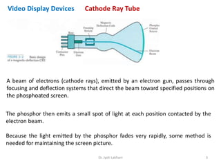
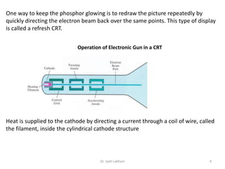
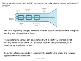
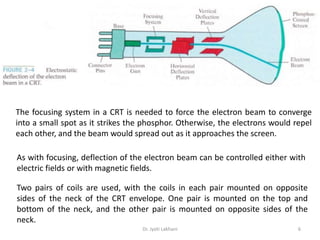
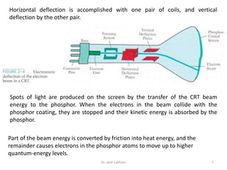
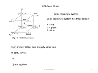
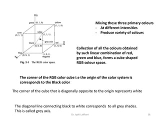
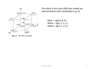
Dr. Jyoti Lakhani 1
Elements of Graphic Systems
Dr. Jyoti Lakhani 2
Input Devices
Output Devices
Monitors CRTs
Cathode Ray Tube
Dr. Jyoti Lakhani 3
Video Display Devices
A beam of electrons (cathode rays), emitted by an electron gun, passes through
focusing and deflection systems that direct the beam toward specified positions on
the phosphoated screen.
The phosphor then emits a small spot of light at each position contacted by the
electron beam.
Because the light emitted by the phosphor fades very rapidly, some method is
needed for maintaining the screen picture.
Dr. Jyoti Lakhani 4
One way to keep the phosphor glowing is to redraw the picture repeatedly by
quickly directing the electron beam back over the same points. This type of display
is called a refresh CRT.
Operation of Electronic Gun in a CRT
Heat is supplied to the cathode by directing a current through a coil of wire, called
the filament, inside the cylindrical cathode structure
Dr. Jyoti Lakhani 5
the free, negatively charged electrons are then accelerated toward the phosphor
coating by a high positive voltage.
The accelerating voltage can be generated with a positively charged metal
coating on the inside of the CRT envelope near the phosphor screen, or an
accelerating anode can be used
Sometime electron gun is built to contain the accelerating anode and focusing
system within the same unit.
This causes electrons to be 'kiled off" the hot cathode surface In the vacuum inside the CRT
envelope,
Dr. Jyoti Lakhani 6
The focusing system in a CRT is needed to force the electron beam to converge
into a small spot as it strikes the phosphor. Otherwise, the electrons would repel
each other, and the beam would spread out as it approaches the screen.
As with focusing, deflection of the electron beam can be controlled either with
electric fields or with magnetic fields.
Two pairs of coils are used, with the coils in each pair mounted on opposite
sides of the neck of the CRT envelope. One pair is mounted on the top and
bottom of the neck, and the other pair is mounted on opposite sides of the
neck.
Dr. Jyoti Lakhani 7
Horizontal deflection is accomplished with one pair of coils, and vertical
deflection by the other pair.
Spots of light are produced on the screen by the transfer of the CRT beam
energy to the phosphor. When the electrons in the beam collide with the
phosphor coating, they are stopped and their kinetic energy is absorbed by the
phosphor.
Part of the beam energy is converted by friction into heat energy, and the
remainder causes electrons in the phosphor atoms to move up to higher
quantum-energy levels.
Dr. Jyoti Lakhani 8
After a short time, the "excited phosphor electrons begin dropping back to their
stable ground state, giving up their extra energy as small quantums of Light
energy.
What we see on the screen is the combined effect of all the electron light
emissions: a glowing spot that quickly fades after all the excited phosphor
electrons have returned to their ground energy level
. The frequency (or color) of the light emitted by the phosphor is proportional to
the energy difference between the excited quantum state and the ground state.
Dr. Jyoti Lakhani 9
Colors in CRTs
Different kinds of phosphors are available for use in a CRT
Besides color, a major difference between phosphors is their persistence: how
long they continue to emit light after the CRT beam is removed.
Persistence is defined as the time it takes the emitted light from the screen to
decay to one-tenth of its original intensity.
Lower persistence phosphor is require higher refresh rates to maintain a picture
on the screen without flicker.
A phosphor with low persistence is useful for animation
A high-persistence phosphor is useful for displaying highly complex, static
pictures.
Although some phosphors have a persistence greater than 1 second, graphics
monitors are usually constructed with a persistence in the range from 10 to 60
microseconds.
Dr. Jyoti Lakhani 10
Resolution of the screen
The maximum number of points that can be displayed without overlap on a CRT is
referred to as the resolution
Spot intensity has a Gaussian distribution, so two adjacent spots will appear
distinct as long as their separation is greater than the diameter at which each
spot has an intensity of about 60 percent of that at the center of the spot.
Spot size also depends on intensity. As more
electrons are accelerated toward the phosphor per
second, the CRT beam diameter and the illuminated
spot increase.
Thus, resolution of a CRT is dependent on the type of
phosphor, the intensity to be displayed, and the
focusing and deflection systems.
Dr. Jyoti Lakhani 11
Aspect Ratio is the –
ratio of vertical points to horizontal points necessary to produce
equal-length lines in both directions on the screen.
(Sometimes aspect ratio is stated in terms of the ratio of
horizontal to vertical points.)
An aspect ratio of 3/4 means that a vertical line plotted with three
points has the same length as a horizontal line plotted with four
points.
Aspect Raio
Dr. Jyoti Lakhani 12
Image Representation
A digital image is composed of discrete pixels
These pixels are arranged in rows and columns -> form a rectangular area -> called RAST
Total number of pixels in an image = function of size of the image and number
of pixel per unit length (horizontal and vertical)
Total pixel = f( Image_Size, Resolution)
Find total number of pixel in an 3 x 2 inch image at resolution of 300 pixel
per inch (i.e. 300 x 300)
Total no. of pixels = 3 * 2 * 300 * 300
Dr. Jyoti Lakhani 13
Ratio of image’s width to height is called Aspect Ratio
Aspect ratio of an image = width x height
Measured in -
unit length or number of pixels
Aspect ratio of 2 x 2 image = 1/1
Aspect ratio of 512 x 512 image = 1/1
Aspect ratio to 1024 x 768 image = 4/3
Aspect Ratio of an image
Dr. Jyoti Lakhani 14
Coordinates of an image
Individual pixels in an image can be referenced by their coordinates
Lower left pixel of the image is consider as origin (0 x 0 ) of pixel coordinate system
Pixel at lower right corner of 640 x 480 image would be –
(639, 479)
(0,0)
…
(639,
479)
640 x 480 image
Dr. Jyoti Lakhani 15
RGB Color Model
Color coordinate system
Color coordinate system has three colours-
R – red
G – green
B - blue
Each primary colour take intensity value from –
0 (off / lowest)
To
1 (on / highest)
Dr. Jyoti Lakhani 16
Mixing these three primary colours
- At different intensities
- Produce variety of colours
Collection of all the colours obtained
by such linear combination of red,
green and blue, forms a cube shaped
RGB colour space.
The corner of the RGB color cube i.e the origin of the color system is
corresponds to the Black color
The corner of the cube that is diagonally opposite to the origin represents white
The diagonal line connecting black to white corresponds to all grey shades.
This is called grey axis.
Dr. Jyoti Lakhani 17
The colors in this cubic RGB color model are
represented by color coordinates (r, g, b)
Black = rgb( 0, 0, 0 )
White = rgb ( 1, 1, 1 )
Yellow = rgb ( 1, 1, 0 )

CG02 Computer Graphic Systems.ppsx

  • 1.
  • 2.
    Elements of GraphicSystems Dr. Jyoti Lakhani 2 Input Devices Output Devices Monitors CRTs
  • 3.
    Cathode Ray Tube Dr.Jyoti Lakhani 3 Video Display Devices A beam of electrons (cathode rays), emitted by an electron gun, passes through focusing and deflection systems that direct the beam toward specified positions on the phosphoated screen. The phosphor then emits a small spot of light at each position contacted by the electron beam. Because the light emitted by the phosphor fades very rapidly, some method is needed for maintaining the screen picture.
  • 4.
    Dr. Jyoti Lakhani4 One way to keep the phosphor glowing is to redraw the picture repeatedly by quickly directing the electron beam back over the same points. This type of display is called a refresh CRT. Operation of Electronic Gun in a CRT Heat is supplied to the cathode by directing a current through a coil of wire, called the filament, inside the cylindrical cathode structure
  • 5.
    Dr. Jyoti Lakhani5 the free, negatively charged electrons are then accelerated toward the phosphor coating by a high positive voltage. The accelerating voltage can be generated with a positively charged metal coating on the inside of the CRT envelope near the phosphor screen, or an accelerating anode can be used Sometime electron gun is built to contain the accelerating anode and focusing system within the same unit. This causes electrons to be 'kiled off" the hot cathode surface In the vacuum inside the CRT envelope,
  • 6.
    Dr. Jyoti Lakhani6 The focusing system in a CRT is needed to force the electron beam to converge into a small spot as it strikes the phosphor. Otherwise, the electrons would repel each other, and the beam would spread out as it approaches the screen. As with focusing, deflection of the electron beam can be controlled either with electric fields or with magnetic fields. Two pairs of coils are used, with the coils in each pair mounted on opposite sides of the neck of the CRT envelope. One pair is mounted on the top and bottom of the neck, and the other pair is mounted on opposite sides of the neck.
  • 7.
    Dr. Jyoti Lakhani7 Horizontal deflection is accomplished with one pair of coils, and vertical deflection by the other pair. Spots of light are produced on the screen by the transfer of the CRT beam energy to the phosphor. When the electrons in the beam collide with the phosphor coating, they are stopped and their kinetic energy is absorbed by the phosphor. Part of the beam energy is converted by friction into heat energy, and the remainder causes electrons in the phosphor atoms to move up to higher quantum-energy levels.
  • 8.
    Dr. Jyoti Lakhani8 After a short time, the "excited phosphor electrons begin dropping back to their stable ground state, giving up their extra energy as small quantums of Light energy. What we see on the screen is the combined effect of all the electron light emissions: a glowing spot that quickly fades after all the excited phosphor electrons have returned to their ground energy level . The frequency (or color) of the light emitted by the phosphor is proportional to the energy difference between the excited quantum state and the ground state.
  • 9.
    Dr. Jyoti Lakhani9 Colors in CRTs Different kinds of phosphors are available for use in a CRT Besides color, a major difference between phosphors is their persistence: how long they continue to emit light after the CRT beam is removed. Persistence is defined as the time it takes the emitted light from the screen to decay to one-tenth of its original intensity. Lower persistence phosphor is require higher refresh rates to maintain a picture on the screen without flicker. A phosphor with low persistence is useful for animation A high-persistence phosphor is useful for displaying highly complex, static pictures. Although some phosphors have a persistence greater than 1 second, graphics monitors are usually constructed with a persistence in the range from 10 to 60 microseconds.
  • 10.
    Dr. Jyoti Lakhani10 Resolution of the screen The maximum number of points that can be displayed without overlap on a CRT is referred to as the resolution Spot intensity has a Gaussian distribution, so two adjacent spots will appear distinct as long as their separation is greater than the diameter at which each spot has an intensity of about 60 percent of that at the center of the spot. Spot size also depends on intensity. As more electrons are accelerated toward the phosphor per second, the CRT beam diameter and the illuminated spot increase. Thus, resolution of a CRT is dependent on the type of phosphor, the intensity to be displayed, and the focusing and deflection systems.
  • 11.
    Dr. Jyoti Lakhani11 Aspect Ratio is the – ratio of vertical points to horizontal points necessary to produce equal-length lines in both directions on the screen. (Sometimes aspect ratio is stated in terms of the ratio of horizontal to vertical points.) An aspect ratio of 3/4 means that a vertical line plotted with three points has the same length as a horizontal line plotted with four points. Aspect Raio
  • 12.
    Dr. Jyoti Lakhani12 Image Representation A digital image is composed of discrete pixels These pixels are arranged in rows and columns -> form a rectangular area -> called RAST Total number of pixels in an image = function of size of the image and number of pixel per unit length (horizontal and vertical) Total pixel = f( Image_Size, Resolution) Find total number of pixel in an 3 x 2 inch image at resolution of 300 pixel per inch (i.e. 300 x 300) Total no. of pixels = 3 * 2 * 300 * 300
  • 13.
    Dr. Jyoti Lakhani13 Ratio of image’s width to height is called Aspect Ratio Aspect ratio of an image = width x height Measured in - unit length or number of pixels Aspect ratio of 2 x 2 image = 1/1 Aspect ratio of 512 x 512 image = 1/1 Aspect ratio to 1024 x 768 image = 4/3 Aspect Ratio of an image
  • 14.
    Dr. Jyoti Lakhani14 Coordinates of an image Individual pixels in an image can be referenced by their coordinates Lower left pixel of the image is consider as origin (0 x 0 ) of pixel coordinate system Pixel at lower right corner of 640 x 480 image would be – (639, 479) (0,0) … (639, 479) 640 x 480 image
  • 15.
    Dr. Jyoti Lakhani15 RGB Color Model Color coordinate system Color coordinate system has three colours- R – red G – green B - blue Each primary colour take intensity value from – 0 (off / lowest) To 1 (on / highest)
  • 16.
    Dr. Jyoti Lakhani16 Mixing these three primary colours - At different intensities - Produce variety of colours Collection of all the colours obtained by such linear combination of red, green and blue, forms a cube shaped RGB colour space. The corner of the RGB color cube i.e the origin of the color system is corresponds to the Black color The corner of the cube that is diagonally opposite to the origin represents white The diagonal line connecting black to white corresponds to all grey shades. This is called grey axis.
  • 17.
    Dr. Jyoti Lakhani17 The colors in this cubic RGB color model are represented by color coordinates (r, g, b) Black = rgb( 0, 0, 0 ) White = rgb ( 1, 1, 1 ) Yellow = rgb ( 1, 1, 0 )

Editor's Notes