Downloaded 194 times
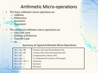
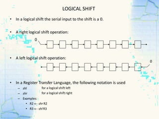
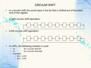
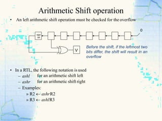
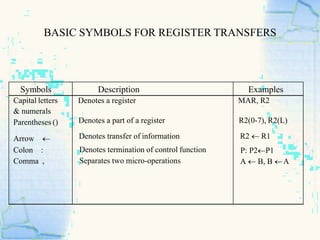


The document discusses register transfer language and micro-operations in digital systems. It describes (1) how register transfer language can be used to describe the sequence of micro-operations involved in any computer function, (2) the four main types of micro-operations - register transfer, arithmetic, logic, and shift micro-operations, giving examples of each, and (3) how register transfers and bus transfers are represented in register transfer language.