Downloaded 129 times
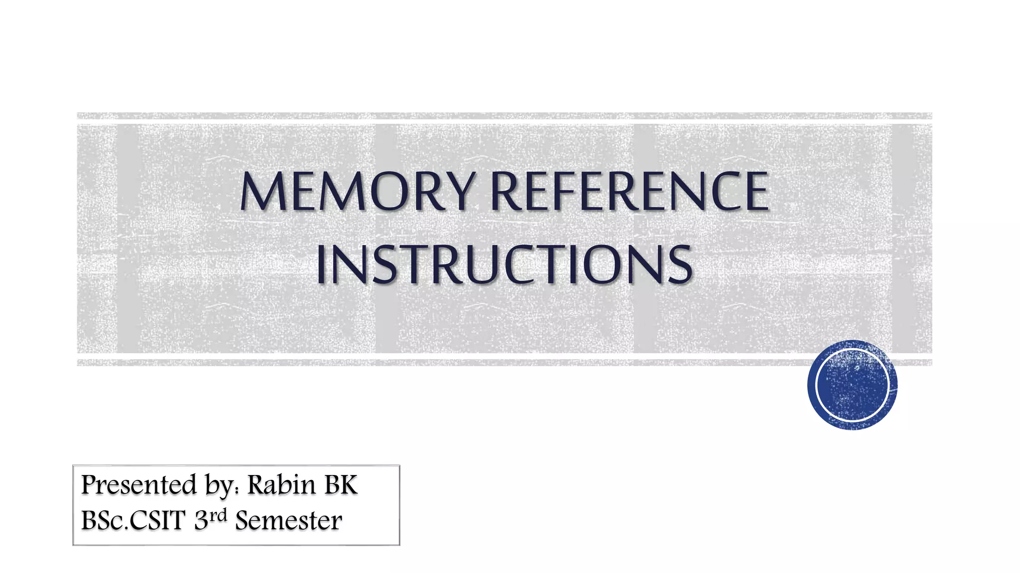
![AND to AC
Performs the AND logic operations on pairs of bits in AC and the
memory word specified by the effective address
Two timing signals are needed
• In T4 transfering operand from memory into DR
• In T5 transfering result of AND logic operation between the contents
of DR and AC
• In T5 SC is cleared to 0 and control is transfered to T0 to start a new
instruction cycle
Example:
• D0T4: DR←M[AR]
• D0T5: AC←AC∧ DR, SC←0
5
Instructions](https://image.slidesharecdn.com/cafirstpresentation-180726074253/85/Memory-Reference-Instructions-5-320.jpg)
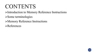
![ADD to AC
Adds the contents of memory word specified by the effective
address to the value of AC
Sum is transferred into AC and the output carry Cout is transferred to
the E(extended accumulator) flip flop
Two timing signals are needed but decoder D1 instead of D0
Example:
• D1T4: DR←M[AR]
• D1T5: AC←AC+DR, E←Cout SC←0
6
Instructions cont...](https://image.slidesharecdn.com/cafirstpresentation-180726074253/85/Memory-Reference-Instructions-6-320.jpg)
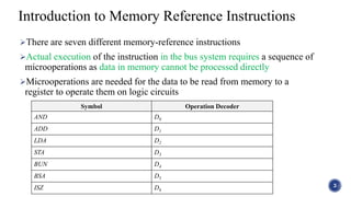
![LDA:Load to AC
Tranfers the memory word specified by the effective address to AC
Necessary to read the memory word into DR first and transfer the
contents of DR into AC
there is no direct path from bus into AC
to maintain one clock cycle as well
Example:
D2T4: DR←M[AR]
D2T5: AC←DR SC←0
7
Instructions cont...](https://image.slidesharecdn.com/cafirstpresentation-180726074253/85/Memory-Reference-Instructions-7-320.jpg)
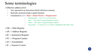
![STA:Store AC
Stores the content of AC into the memory word specified by the
effective address
The output of AC is applied to the bus and the data input of
memory is connected to the bus
Example:
D3T4: M[AR]←AC, SC←0
8
Instructions cont...](https://image.slidesharecdn.com/cafirstpresentation-180726074253/85/Memory-Reference-Instructions-8-320.jpg)
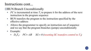
![BSA:Branch and Save Return Address
Useful for branching to a portion of the program called a subroutine
or procedure
When executed, it stores the address of the next instruction in
sequence (which is available in PC) into a memory location
specified by the effective address
(Effective address + 1) is then transferred to PC to serve as the
address of the first instruction in the subroutine
The return to the original program is accomplished by the BUN
instruction placed at the end of the subroutine
Example:
D5T4: M[AR]←PC, AR←AR+1
D5T5: PC ← AR, SC←0
10
Instructions cont...](https://image.slidesharecdn.com/cafirstpresentation-180726074253/85/Memory-Reference-Instructions-10-320.jpg)
![ISZ:Increment and Skip if Zero
Increments the word specified by the effective address
If the incremented value is equal to 0, PC is incremented by 1
When a negative number(in 2's compelement) stored in memory word is
repeatedy incremented by 1 it eventually reaches zero
At this time PC is incremented by one in order to skip the next
instruction in the program
It is necessary to read the word into DR, increment DR and store the
word back into memory since it is not possible to increment a word
inside the memory
Example:
D6T4: DR←M[AR]
D6T5: DR←DR+1
D6T6: M[AR] ← DR, if (DR=0) then (PC←PC+1), SC←0
11
Instructions cont...](https://image.slidesharecdn.com/cafirstpresentation-180726074253/85/Memory-Reference-Instructions-11-320.jpg)


The document provides an overview of memory reference instructions, detailing the types and functions of seven specific instructions used in computer architecture. It explains the process of executing these instructions, including the roles of microoperations, effective addresses, and various registers. Additionally, examples of the instructions such as add, load, store, and branching operations are illustrated, emphasizing their significance in accessing and manipulating memory data.