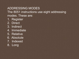
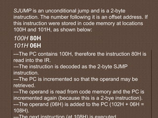
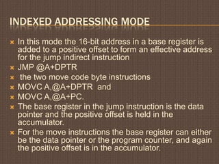
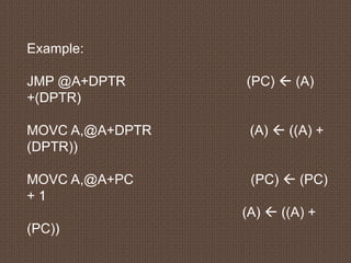
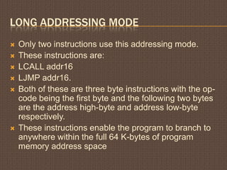
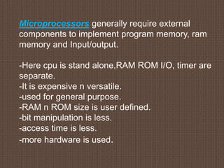
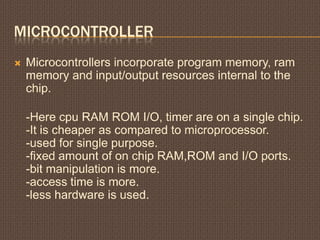
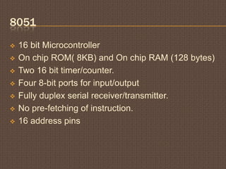
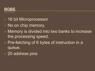
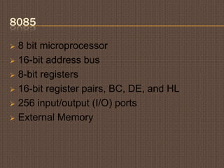
8051 ADDRESSING MODES (CONT.)
By: Mayank Garg
2013H140040H
“What is an addressing mode ?“
Addressing mode is the way of addressing a
memory location in instruction. Microcntroller
needs data or operands on which the operation is
to be performed. The method of specifying source
of operand and output of result in an instruction is
known as addressing mode.
“What is an addressing mode ?“
Addressing mode is the way of addressing a memory
location in instruction. Microcntroller needs data or
operands on which the operation is to be performed. The
method of specifying source of operand and output of result
in an instruction is known as addressing mode.
Now question arises:
How many types of addressing
modes?
ADDRESSING MODES
The 8051 instructions use eight addressing
modes. These are:
1. Register
2. Direct
3. Indirect
4. Immediate
5. Relative
6. Absolute
7. Indexed
8. Long
ABSOLUTE ADDRESSING MODE
 There are only two instructions that use this
addressing:
 ACALL (absolute call)
 AJMP (absolute jump).
 These instructions perform branching within the
current 2K page of program memory.
 The branch address is obtained by successively
concatenating the five high-order bits of the
program counter, bits 5 – 7 of the op-code,and
the second byte of the instruction.
CONTD…
 The operation of the AJMP instruction is detailed
below:
 AJMP address
(PC) <- (PC) + 2
(PC10-PC0) <- address10 - address0
 The eleven least significant bits of the PC are
altered. The five most significant bits remain the
same. This means the AJMP will only allow you
to jump to a location in the same 2K page as the
instruction directly after the jump.
For example:
If the label THERE represents an instruction at address 0F46H and the
instruction AJMP THERE is in memory at locations 0900H and 0901H, the
assembler will encode the instruction as
11100001 1st byte (A10 - A8 + opcode)
01000110 2nd byte (A7 - A0)
The underlined bits are the low-order 11 bits of the destination address, 0F46H =
0000111101000110B. The upper five bits in the program counter will not change
when this instruction executes. Note that both the AJMP instruction and the
destination are within the 2K page bounded by 0800H and 0FFFH, and therefore
have the upper five address bits in common.
ANY Query regarding
this??
Lets move to next….
RELATIVE ADDRESING
 Relative addressing is used only with certain
jump instructions. The system executes a jump
by changing the contents of the PC to the
address of the next instruction to be executed.
 For example, if we wished to jump to the
instruction stored at location 4EH in code
memory, the PC would be loaded with 4EH.
Then, during the next execution cycle the
contents of the PC (4EH) are placed on the
address bus and the instruction at 4EH is
retrieved.
SJUMP is an unconditional jump and is a 2-byte
instruction. The number following it is an offset address. If
this instruction were stored in code memory at locations
100H and 101H, as shown below:
100H 80H
101H 06H
---The PC contains 100H, therefore the instruction 80H is
read into the IR.
---The instruction is decoded as the 2-byte SJMP
instruction.
---The PC is incremented so that the operand may be
retrieved.
---The operand is read from code memory and the PC is
incremented again (because this is a 2-bye instruction).
---The operand (06H) is added to the PC (102H + 06H =
108H).
ANY Query regarding
this??
Lets move to next….
INDEXED ADDRESSING MODE
 In this mode the 16-bit address in a base register is
added to a positive offset to form an effective address
for the jump indirect instruction
 JMP @A+DPTR
 the two move code byte instructions
 MOVC A,@A+DPTR and
 MOVC A,@A+PC.
 The base register in the jump instruction is the data
pointer and the positive offset is held in the
accumulator.
 For the move instructions the base register can either
be the data pointer or the program counter, and again
the positive offset is in the accumulator.
Example:
JMP @A+DPTR (PC)  (A)
+(DPTR)
MOVC A,@A+DPTR (A)  ((A) +
(DPTR))
MOVC A,@A+PC (PC)  (PC)
+ 1
(A)  ((A) +
(PC))
ANY Query regarding
this??
Lets move to next….
LONG ADDRESSING MODE
 Only two instructions use this addressing mode.
 These instructions are:
 LCALL addr16
 LJMP addr16.
 Both of these are three byte instructions with the op-
code being the first byte and the following two bytes
are the address high-byte and address low-byte
respectively.
 These instructions enable the program to branch to
anywhere within the full 64 K-bytes of program
memory address space
ANY Query regarding
this??
Lets move to next….
INDIRECT ADDRESSING MODE
 In this mode of addressing the instruction
performs an operation on the data whose
address is contained in register R0 or R1.
Instructions using indirect addressing are
single byte instructions.
 In 8051 assembly language the symbol @
before R0 or
 SUBB A, @R0 R1
(denotes indirect addressing.)
This instruction performs the operation:
(A) (A) (C)  ((R0)).
For example,
***if you had an array of 8-bit numbers stored in
memory, starting at address 30H, you may wish to examine
the contents of each number in the array (perhaps to find the
smallest number).
***To do so, you would need to read location 30H, then
31H, then 32H and so on.
This can be achieved using indirect addressing. R0 and
R1 may be used as pointer registers.
MOV A, @Ri (where Ri is either R0 or R1.)
Now, we can read the contents of location 30H through
indirect addressing:
MOV R0, #30H
MOV A, @R0
ANY Query regarding
this??
So now we know all addressing modes.
What is next now??
What is the difference between
Microprocessor and Microcontroller???
Microprocessors generally require external
components to implement program memory, ram
memory and Input/output.
-Here cpu is stand alone,RAM ROM I/O, timer are
separate.
-It is expensive n versatile.
-used for general purpose.
-RAM n ROM size is user defined.
-bit manipulation is less.
-access time is less.
-more hardware is used.
MICROCONTROLLER
 Microcontrollers incorporate program memory, ram
memory and input/output resources internal to the
chip.
-Here cpu RAM ROM I/O, timer are on a single chip.
-It is cheaper as compared to microprocessor.
-used for single purpose.
-fixed amount of on chip RAM,ROM and I/O ports.
-bit manipulation is more.
-access time is more.
-less hardware is used.
WHAT IS DIFFERENCE BETWEEN:
 8085
 8086
 8051
???
8051
 16 bit Microcontroller
 On chip ROM( 8KB) and On chip RAM (128 bytes)
 Two 16 bit timer/counter.
 Four 8-bit ports for input/output
 Fully duplex serial receiver/transmitter.
 No pre-fetching of instruction.
 16 address pins
8086
 16 bit Microprocessor
 No on chip memory.
 Memory is divided into two banks to increase
the processing speed.
 Pre-fetching of 6 bytes of instruction in a
queue.
 20 address pins
8085
 8 bit microprocessor
 16-bit address bus
 8-bit registers
 16-bit register pairs, BC, DE, and HL
 256 input/output (I/O) ports
 External Memory
REFERENCES
 https://www.silabs.com/Support%20Documents/Softw
are/8051_Instruction_Set.pdf
 http://coitweb.uncc.edu/~abw/ITCS3182F09/slides3.p
df
 http://www.cs.iit.edu/~virgil/cs470/Book/chapter4.pd
 http://www.slideshare.net/chappidi_saritha/addressin
g-modes-of-8051
 http://www.edsim51.com/8051Notes/8051/instruction
SetSummary.html
 http://www.nptel.iitm.ac.in/courses/Webcourse-
contents/IITKANPUR/microcontrollers/micro/ui/Cours
e_home2_6.htm
So now move to what is
instruction?
Types of instructions???

Addressing Modes

  • 1.
    8051 ADDRESSING MODES(CONT.) By: Mayank Garg 2013H140040H
  • 2.
    “What is anaddressing mode ?“
  • 3.
    “What is anaddressing mode ?“ Addressing mode is the way of addressing a memory location in instruction. Microcntroller needs data or operands on which the operation is to be performed. The method of specifying source of operand and output of result in an instruction is known as addressing mode.
  • 4.
    “What is anaddressing mode ?“ Addressing mode is the way of addressing a memory location in instruction. Microcntroller needs data or operands on which the operation is to be performed. The method of specifying source of operand and output of result in an instruction is known as addressing mode. Now question arises: How many types of addressing modes?
  • 5.
    ADDRESSING MODES The 8051instructions use eight addressing modes. These are: 1. Register 2. Direct 3. Indirect 4. Immediate 5. Relative 6. Absolute 7. Indexed 8. Long
  • 6.
    ABSOLUTE ADDRESSING MODE There are only two instructions that use this addressing:  ACALL (absolute call)  AJMP (absolute jump).  These instructions perform branching within the current 2K page of program memory.  The branch address is obtained by successively concatenating the five high-order bits of the program counter, bits 5 – 7 of the op-code,and the second byte of the instruction.
  • 7.
    CONTD…  The operationof the AJMP instruction is detailed below:  AJMP address (PC) <- (PC) + 2 (PC10-PC0) <- address10 - address0  The eleven least significant bits of the PC are altered. The five most significant bits remain the same. This means the AJMP will only allow you to jump to a location in the same 2K page as the instruction directly after the jump.
  • 8.
    For example: If thelabel THERE represents an instruction at address 0F46H and the instruction AJMP THERE is in memory at locations 0900H and 0901H, the assembler will encode the instruction as 11100001 1st byte (A10 - A8 + opcode) 01000110 2nd byte (A7 - A0) The underlined bits are the low-order 11 bits of the destination address, 0F46H = 0000111101000110B. The upper five bits in the program counter will not change when this instruction executes. Note that both the AJMP instruction and the destination are within the 2K page bounded by 0800H and 0FFFH, and therefore have the upper five address bits in common.
  • 9.
  • 10.
    RELATIVE ADDRESING  Relativeaddressing is used only with certain jump instructions. The system executes a jump by changing the contents of the PC to the address of the next instruction to be executed.  For example, if we wished to jump to the instruction stored at location 4EH in code memory, the PC would be loaded with 4EH. Then, during the next execution cycle the contents of the PC (4EH) are placed on the address bus and the instruction at 4EH is retrieved.
  • 11.
    SJUMP is anunconditional jump and is a 2-byte instruction. The number following it is an offset address. If this instruction were stored in code memory at locations 100H and 101H, as shown below: 100H 80H 101H 06H ---The PC contains 100H, therefore the instruction 80H is read into the IR. ---The instruction is decoded as the 2-byte SJMP instruction. ---The PC is incremented so that the operand may be retrieved. ---The operand is read from code memory and the PC is incremented again (because this is a 2-bye instruction). ---The operand (06H) is added to the PC (102H + 06H = 108H).
  • 12.
  • 13.
    INDEXED ADDRESSING MODE In this mode the 16-bit address in a base register is added to a positive offset to form an effective address for the jump indirect instruction  JMP @A+DPTR  the two move code byte instructions  MOVC A,@A+DPTR and  MOVC A,@A+PC.  The base register in the jump instruction is the data pointer and the positive offset is held in the accumulator.  For the move instructions the base register can either be the data pointer or the program counter, and again the positive offset is in the accumulator.
  • 14.
    Example: JMP @A+DPTR (PC) (A) +(DPTR) MOVC A,@A+DPTR (A)  ((A) + (DPTR)) MOVC A,@A+PC (PC)  (PC) + 1 (A)  ((A) + (PC))
  • 15.
  • 16.
    LONG ADDRESSING MODE Only two instructions use this addressing mode.  These instructions are:  LCALL addr16  LJMP addr16.  Both of these are three byte instructions with the op- code being the first byte and the following two bytes are the address high-byte and address low-byte respectively.  These instructions enable the program to branch to anywhere within the full 64 K-bytes of program memory address space
  • 17.
  • 18.
    INDIRECT ADDRESSING MODE In this mode of addressing the instruction performs an operation on the data whose address is contained in register R0 or R1. Instructions using indirect addressing are single byte instructions.  In 8051 assembly language the symbol @ before R0 or  SUBB A, @R0 R1 (denotes indirect addressing.)
  • 19.
    This instruction performsthe operation: (A) (A) (C)  ((R0)). For example, ***if you had an array of 8-bit numbers stored in memory, starting at address 30H, you may wish to examine the contents of each number in the array (perhaps to find the smallest number). ***To do so, you would need to read location 30H, then 31H, then 32H and so on.
  • 20.
    This can beachieved using indirect addressing. R0 and R1 may be used as pointer registers. MOV A, @Ri (where Ri is either R0 or R1.) Now, we can read the contents of location 30H through indirect addressing: MOV R0, #30H MOV A, @R0
  • 21.
    ANY Query regarding this?? Sonow we know all addressing modes. What is next now??
  • 22.
    What is thedifference between Microprocessor and Microcontroller???
  • 23.
    Microprocessors generally requireexternal components to implement program memory, ram memory and Input/output. -Here cpu is stand alone,RAM ROM I/O, timer are separate. -It is expensive n versatile. -used for general purpose. -RAM n ROM size is user defined. -bit manipulation is less. -access time is less. -more hardware is used.
  • 24.
    MICROCONTROLLER  Microcontrollers incorporateprogram memory, ram memory and input/output resources internal to the chip. -Here cpu RAM ROM I/O, timer are on a single chip. -It is cheaper as compared to microprocessor. -used for single purpose. -fixed amount of on chip RAM,ROM and I/O ports. -bit manipulation is more. -access time is more. -less hardware is used.
  • 25.
    WHAT IS DIFFERENCEBETWEEN:  8085  8086  8051 ???
  • 26.
    8051  16 bitMicrocontroller  On chip ROM( 8KB) and On chip RAM (128 bytes)  Two 16 bit timer/counter.  Four 8-bit ports for input/output  Fully duplex serial receiver/transmitter.  No pre-fetching of instruction.  16 address pins
  • 27.
    8086  16 bitMicroprocessor  No on chip memory.  Memory is divided into two banks to increase the processing speed.  Pre-fetching of 6 bytes of instruction in a queue.  20 address pins
  • 28.
    8085  8 bitmicroprocessor  16-bit address bus  8-bit registers  16-bit register pairs, BC, DE, and HL  256 input/output (I/O) ports  External Memory
  • 29.
    REFERENCES  https://www.silabs.com/Support%20Documents/Softw are/8051_Instruction_Set.pdf  http://coitweb.uncc.edu/~abw/ITCS3182F09/slides3.p df http://www.cs.iit.edu/~virgil/cs470/Book/chapter4.pd  http://www.slideshare.net/chappidi_saritha/addressin g-modes-of-8051  http://www.edsim51.com/8051Notes/8051/instruction SetSummary.html  http://www.nptel.iitm.ac.in/courses/Webcourse- contents/IITKANPUR/microcontrollers/micro/ui/Cours e_home2_6.htm
  • 31.
    So now moveto what is instruction? Types of instructions???