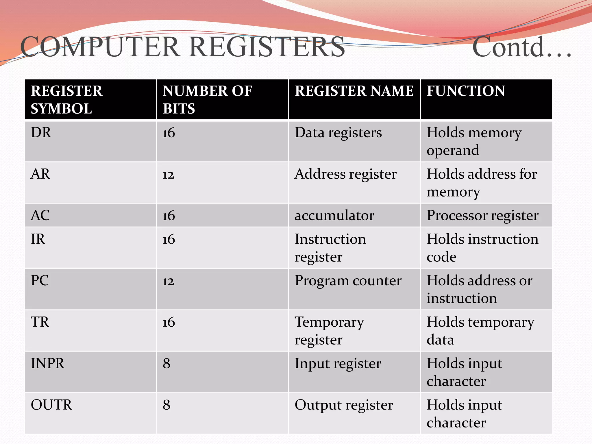
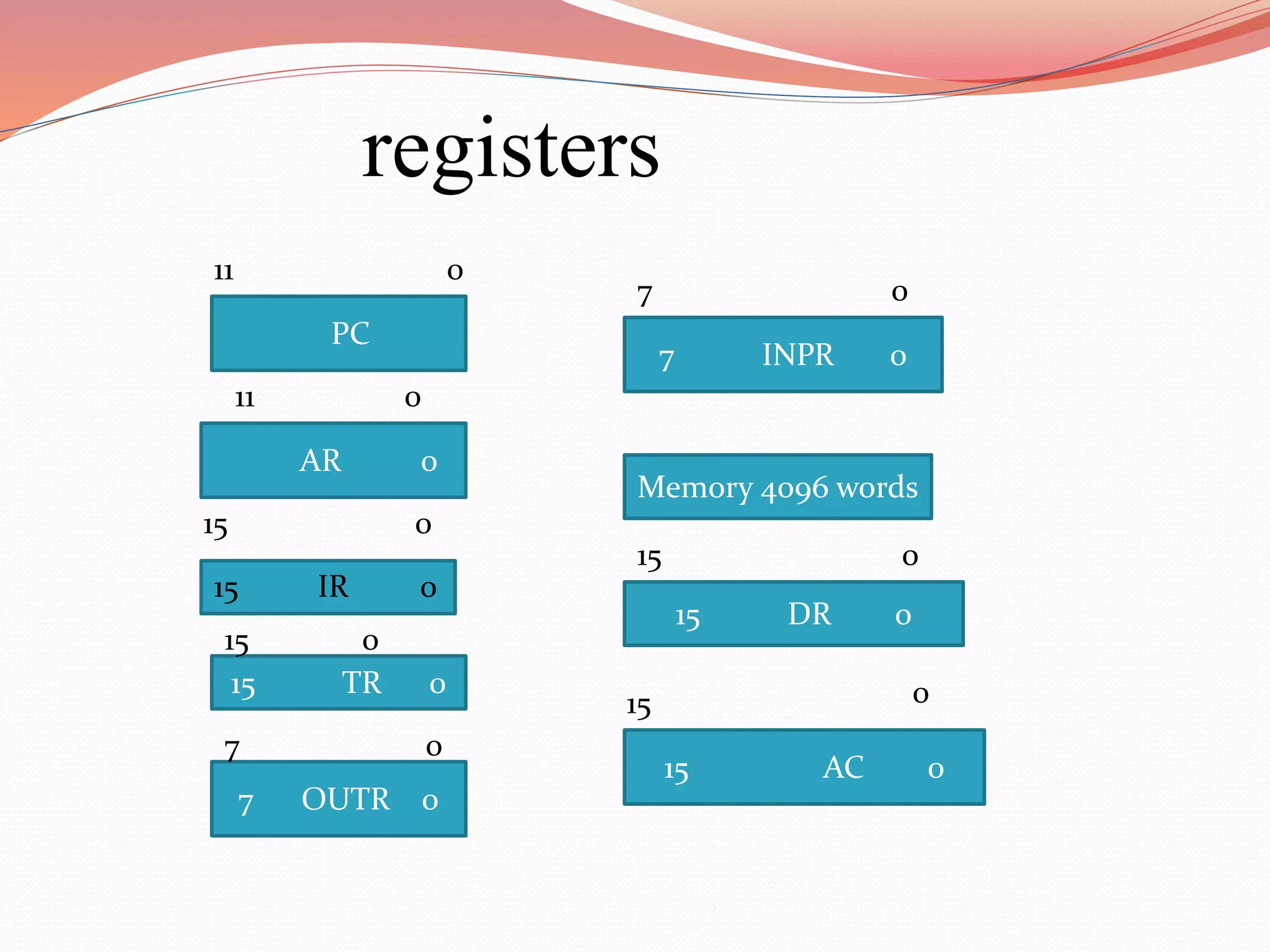
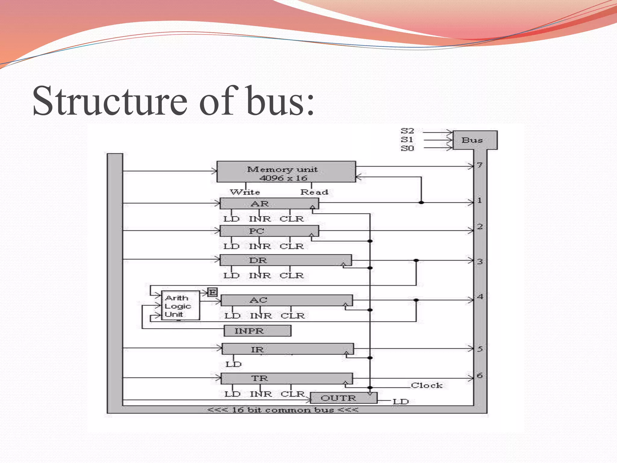
By
T.DEEPIKA
M.SC(INFO TECH)
NADAR SARASWATHI COLLEGE OF ARTS
ANDSCIENCE
COMPUTER REGISTERS
Computer instructions are executed sequentially
one at time.
It stored in consecutive memory locations.
Control reads an instruction from specific
address in memory and execute it.
Then it reads the next instruction in sequence
and executes it, and so on.
This type of instruction sequence need a
counter,
 To calculate the address of the next instruction
after the current instruction is completed.
Register in a control unit is used to store the
instruction code after read from memory.
The Computer needs,
 Processor register for manipulating data.
 Register for holding a memory address.
COMPUTER REGISTERS Contd…
The below table consists of details of all the
registers.
The memory unit has a capacity of 4096
words.
Each word contains 16 bits .
 Twelve bits - To specify the address of an operand.
COMPUTER REGISTERS Contd…
REGISTER
SYMBOL
NUMBER OF
BITS
REGISTER NAME FUNCTION
DR 16 Data registers Holds memory
operand
AR 12 Address register Holds address for
memory
AC 16 accumulator Processor register
IR 16 Instruction
register
Holds instruction
code
PC 12 Program counter Holds address or
instruction
TR 16 Temporary
register
Holds temporary
data
INPR 8 Input register Holds input
character
OUTR 8 Output register Holds input
character
COMPUTER REGISTERS Contd…
Three bits - For operation.
- Part of the instruction.
- To specify a direct address / indirect
address.
Data Register (DR) – To Hold the operand and
read from memory.
Accumulator (AC)register - general purpose
processing register.
COMPUTER REGISTERS Contd…
Instruction register(IR) - instruction read
from the memory and placed in IR.
Temporary Register(TR) - To hold
temporary data during the process.
Memory address register (AR) –
It denotes width of the memory address
it has12 bits
COMPUTER REGISTERS Contd…
Program counter (pc) –
 it has 12 bits.
It holds the address of the next instruction to
be read from memory after the current
instruction is executed.
Through a counting sequence, it causes the
computer to read sequence instruction
previously stored in memory.
COMPUTER REGISTERS Contd…
Branch instruction
Instruction words are read and executed in
sequence.
Unless if it is any interruption occurs the
information are considered as branch
instruction.
A branch instruction calls for a transfer to a
nonconsecutive instruction in the program.
The address part of the branch instruction is
transferred to PC.
COMPUTER REGISTERS Contd…
Two registers.
Input register.(INPR)
Output register.(OUTR)
Both the register holds an 8-bit character
for input and output devices.
PC
AR 0
15 TR 0
Memory 4096 words
7 OUTR 0
15 DR 0
15 AC 0
7 INPR 0
15 IR 0
registers
11 0
11
7 0
15 0
15 0
7 0
0
15 0
15
0
Common bus system
Every computer have eight registers ,
memory unit and control unit.
Paths must be provided to transfer the
information from one registers to another.
And also in between memory and
registers.
Structure of bus:
Number of wires will be excessive if
connection are made between the output
of each registers and the inputs of the
other registers.
In common bus have many registers its is
easily to transfer the information.
The output of seven register is connected
to the common bus.
Specify input is selected for the bus lines.
When in dr we give 3 then the output is
given by binary value 011.
Load is used to receive the data from the
bus during the next clock pulse transation.
 four registers DR,AC,IR and TR
have 16 bits eah.
 Two register AR and PC have 12 bits each since they
hold a memory address.
 When the contents of AR or PC are applied to the 16
bits common bus the four most significant bits are set
to 0’s.
 When AR or PC receive information from the bus only
the 12 least significant bits are transferred into the
rigister.
 The input register INPR and the output register OUTR
have 8 bits each and communicate with the eight least
significant bits in the bus.
 INPR is connected to provide information to the bus
but OUTR can only receive information in the bus.
 The INPR receives a character from an input device
which is when transfer to AC.
 OUTR receives a character from AC and delivers it to
the on output device.OUTR have no transfer to other
register.
 The 16 lines of the common bus receive information
from six register and the memory unit.
 The bus lines are connected to the inputs of six
registers and the memory.
 Five registers have three control inputs
LD(load)
INR(increment)
CLR(clear)
 The input data and output data of the memory are
connected to the common bus,but the memory
address is connected to AR.
 The content of any register can be specified for the
memory data input during write operation.
 The register can receive the data from memory after a
read operation except AC.
 The 16 inputs of AC come from an adder and logic
circuit.this circuit has three sets of inputs.
 They are used to implement register microoperation
such as complement AC and shift AC.16 bit inputs
come from the data register DR.
 The inputs from DR and AC are used for arithmetic
and logic microoperation such as add DR to AC or
AND DR to AC.
 The third set 8 bit inputs come from the input register
INPR.the operation of INPR and OUTR
 The clock transition at the end of the cycle transfer the
content of the bus and logic circuit into AC.
DR<-AC and AC<-DR
can be executed at the same time. this can be done by
placing the content of AC on the bus, enableing the
LD input of DR,transferring the content of DR and
the logic circuit into AC.
The two transfer the arrival of the clock pulse transition
at the end of the clock cycle.
Computer registers

Computer registers

  • 1.
  • 2.
    COMPUTER REGISTERS Computer instructionsare executed sequentially one at time. It stored in consecutive memory locations. Control reads an instruction from specific address in memory and execute it. Then it reads the next instruction in sequence and executes it, and so on.
  • 3.
    This type ofinstruction sequence need a counter,  To calculate the address of the next instruction after the current instruction is completed. Register in a control unit is used to store the instruction code after read from memory. The Computer needs,  Processor register for manipulating data.  Register for holding a memory address. COMPUTER REGISTERS Contd…
  • 4.
    The below tableconsists of details of all the registers. The memory unit has a capacity of 4096 words. Each word contains 16 bits .  Twelve bits - To specify the address of an operand. COMPUTER REGISTERS Contd…
  • 5.
    REGISTER SYMBOL NUMBER OF BITS REGISTER NAMEFUNCTION DR 16 Data registers Holds memory operand AR 12 Address register Holds address for memory AC 16 accumulator Processor register IR 16 Instruction register Holds instruction code PC 12 Program counter Holds address or instruction TR 16 Temporary register Holds temporary data INPR 8 Input register Holds input character OUTR 8 Output register Holds input character COMPUTER REGISTERS Contd…
  • 6.
    Three bits -For operation. - Part of the instruction. - To specify a direct address / indirect address. Data Register (DR) – To Hold the operand and read from memory. Accumulator (AC)register - general purpose processing register. COMPUTER REGISTERS Contd…
  • 7.
    Instruction register(IR) -instruction read from the memory and placed in IR. Temporary Register(TR) - To hold temporary data during the process. Memory address register (AR) – It denotes width of the memory address it has12 bits COMPUTER REGISTERS Contd…
  • 8.
    Program counter (pc)–  it has 12 bits. It holds the address of the next instruction to be read from memory after the current instruction is executed. Through a counting sequence, it causes the computer to read sequence instruction previously stored in memory. COMPUTER REGISTERS Contd…
  • 9.
    Branch instruction Instruction wordsare read and executed in sequence. Unless if it is any interruption occurs the information are considered as branch instruction. A branch instruction calls for a transfer to a nonconsecutive instruction in the program. The address part of the branch instruction is transferred to PC. COMPUTER REGISTERS Contd…
  • 10.
    Two registers. Input register.(INPR) Outputregister.(OUTR) Both the register holds an 8-bit character for input and output devices.
  • 11.
    PC AR 0 15 TR0 Memory 4096 words 7 OUTR 0 15 DR 0 15 AC 0 7 INPR 0 15 IR 0 registers 11 0 11 7 0 15 0 15 0 7 0 0 15 0 15 0
  • 12.
    Common bus system Everycomputer have eight registers , memory unit and control unit. Paths must be provided to transfer the information from one registers to another. And also in between memory and registers.
  • 13.
  • 14.
    Number of wireswill be excessive if connection are made between the output of each registers and the inputs of the other registers. In common bus have many registers its is easily to transfer the information.
  • 15.
    The output ofseven register is connected to the common bus. Specify input is selected for the bus lines. When in dr we give 3 then the output is given by binary value 011. Load is used to receive the data from the bus during the next clock pulse transation.
  • 16.
     four registersDR,AC,IR and TR have 16 bits eah.  Two register AR and PC have 12 bits each since they hold a memory address.  When the contents of AR or PC are applied to the 16 bits common bus the four most significant bits are set to 0’s.  When AR or PC receive information from the bus only the 12 least significant bits are transferred into the rigister.
  • 17.
     The inputregister INPR and the output register OUTR have 8 bits each and communicate with the eight least significant bits in the bus.  INPR is connected to provide information to the bus but OUTR can only receive information in the bus.  The INPR receives a character from an input device which is when transfer to AC.  OUTR receives a character from AC and delivers it to the on output device.OUTR have no transfer to other register.
  • 18.
     The 16lines of the common bus receive information from six register and the memory unit.  The bus lines are connected to the inputs of six registers and the memory.  Five registers have three control inputs LD(load) INR(increment) CLR(clear)
  • 19.
     The inputdata and output data of the memory are connected to the common bus,but the memory address is connected to AR.  The content of any register can be specified for the memory data input during write operation.  The register can receive the data from memory after a read operation except AC.
  • 20.
     The 16inputs of AC come from an adder and logic circuit.this circuit has three sets of inputs.  They are used to implement register microoperation such as complement AC and shift AC.16 bit inputs come from the data register DR.  The inputs from DR and AC are used for arithmetic and logic microoperation such as add DR to AC or AND DR to AC.
  • 21.
     The thirdset 8 bit inputs come from the input register INPR.the operation of INPR and OUTR  The clock transition at the end of the cycle transfer the content of the bus and logic circuit into AC. DR<-AC and AC<-DR can be executed at the same time. this can be done by placing the content of AC on the bus, enableing the LD input of DR,transferring the content of DR and the logic circuit into AC. The two transfer the arrival of the clock pulse transition at the end of the clock cycle.