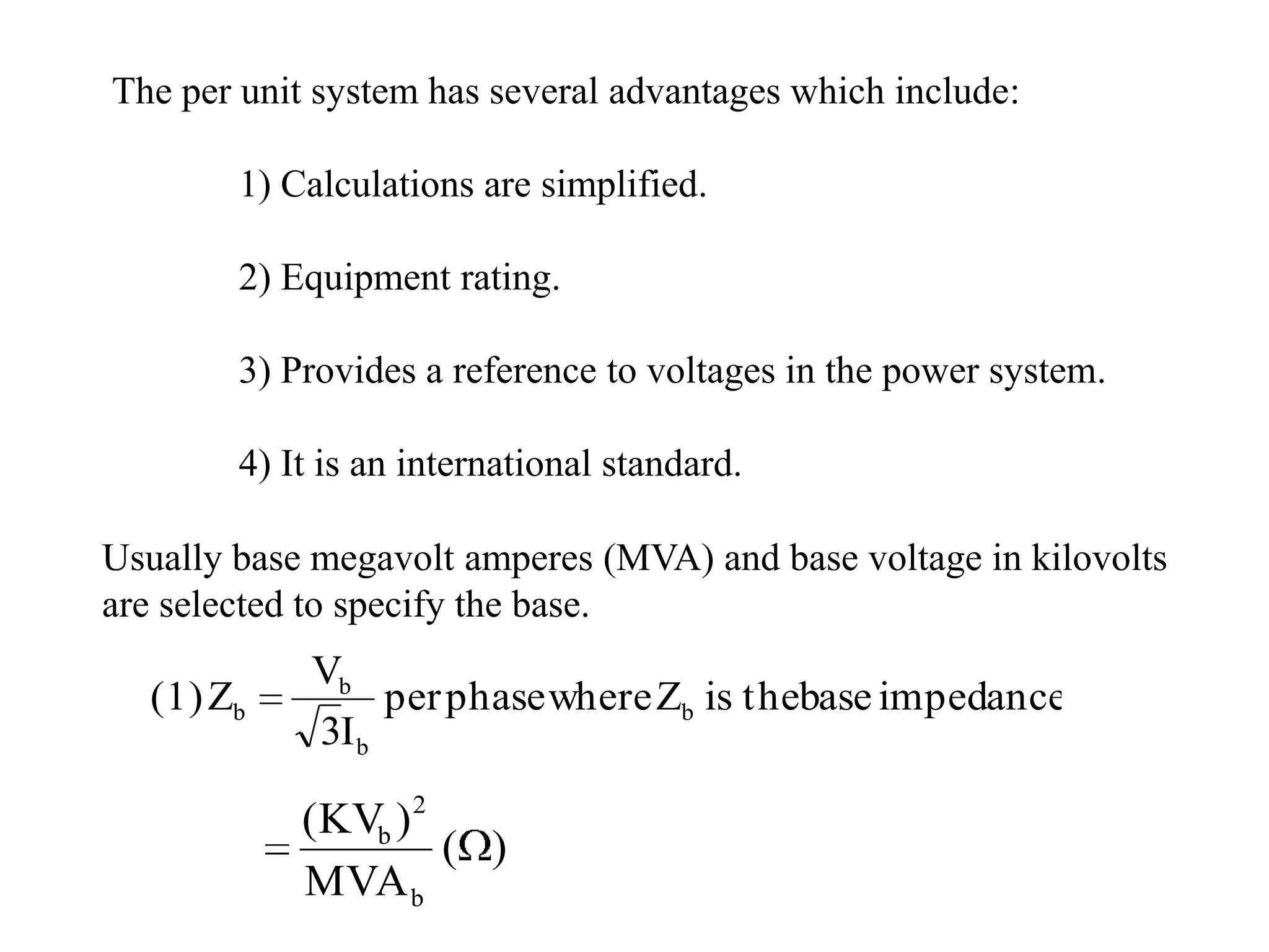
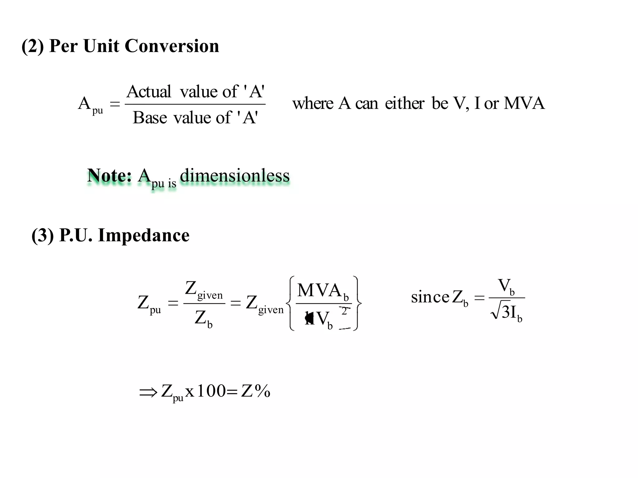
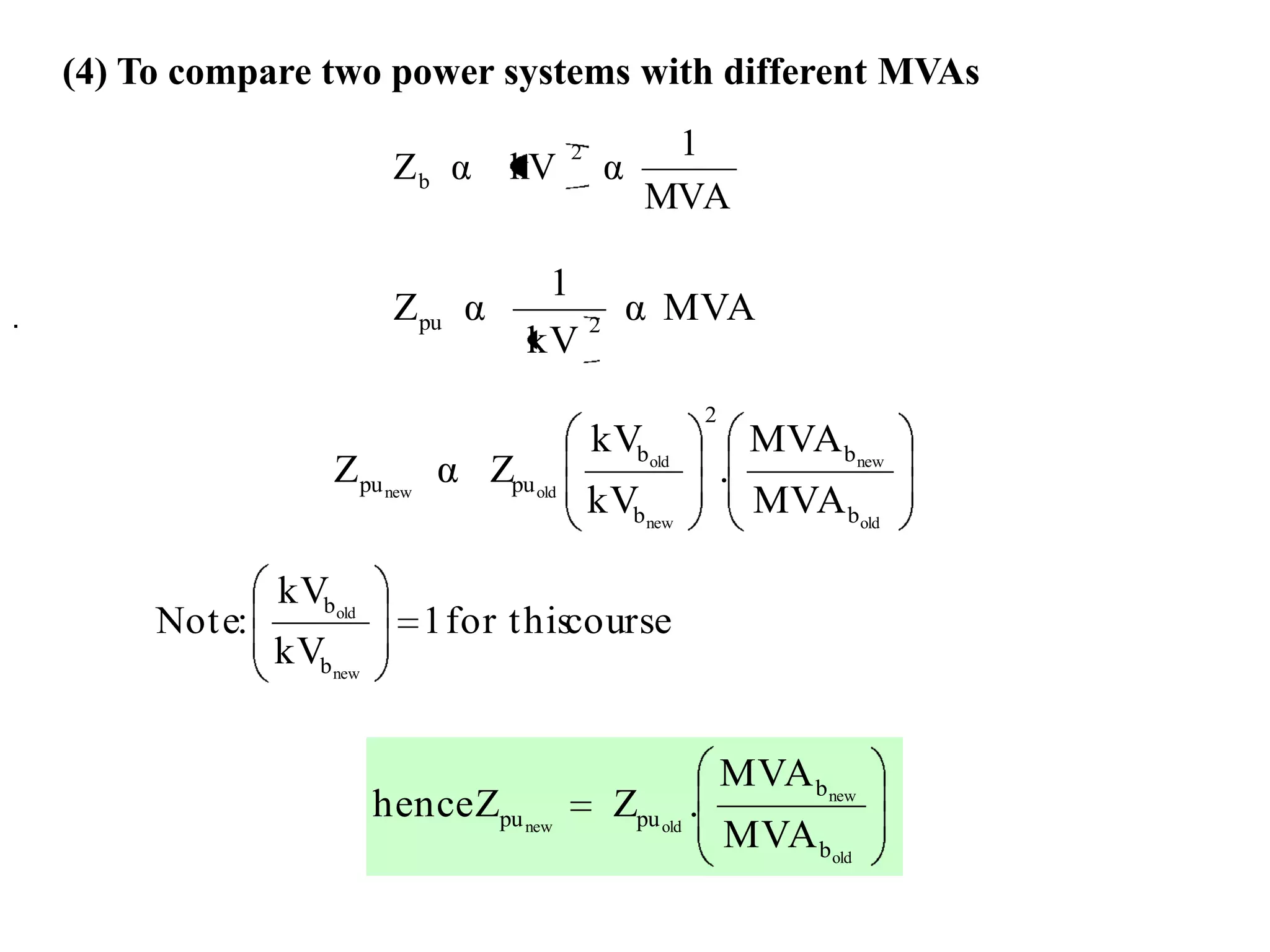
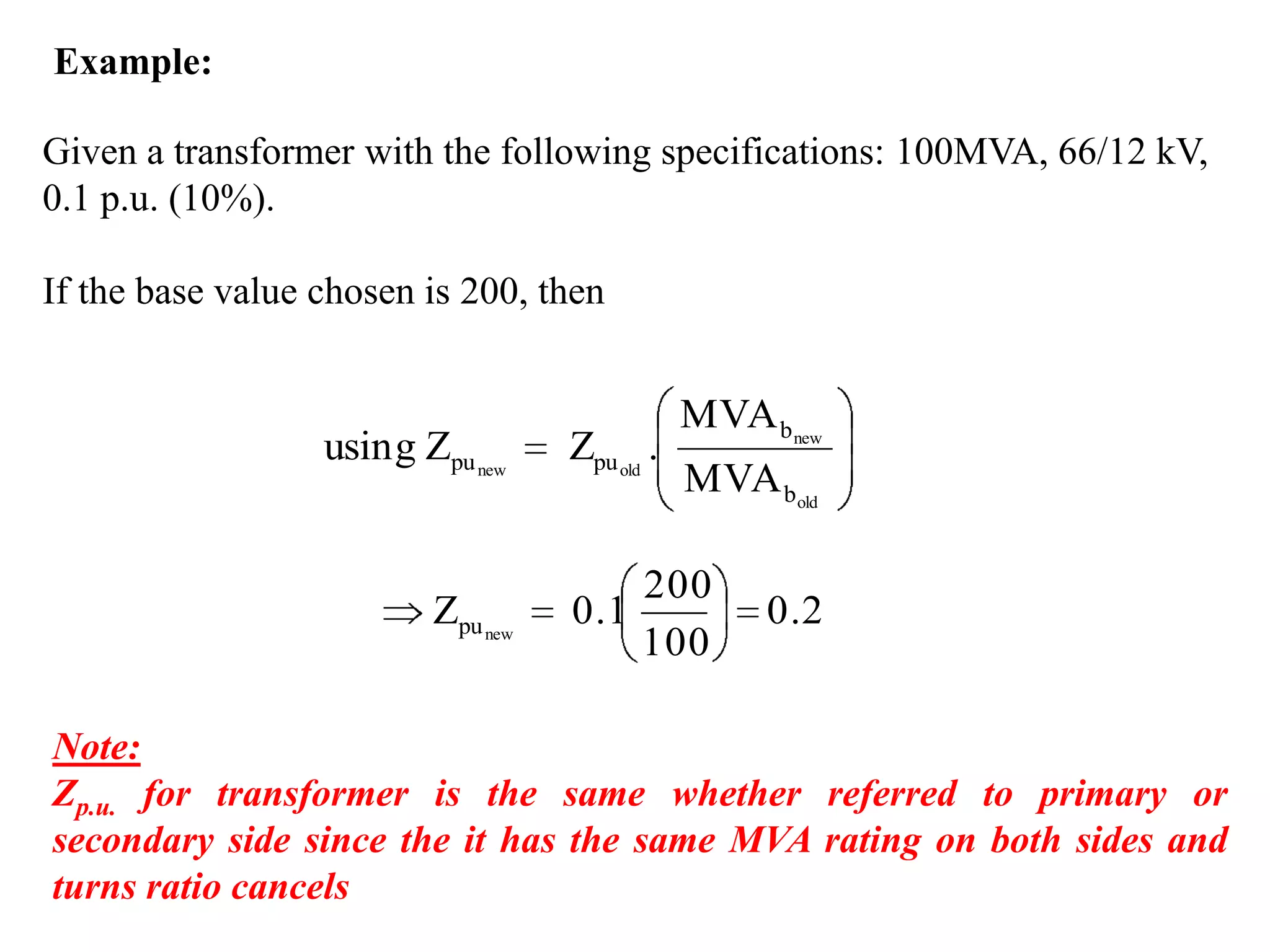
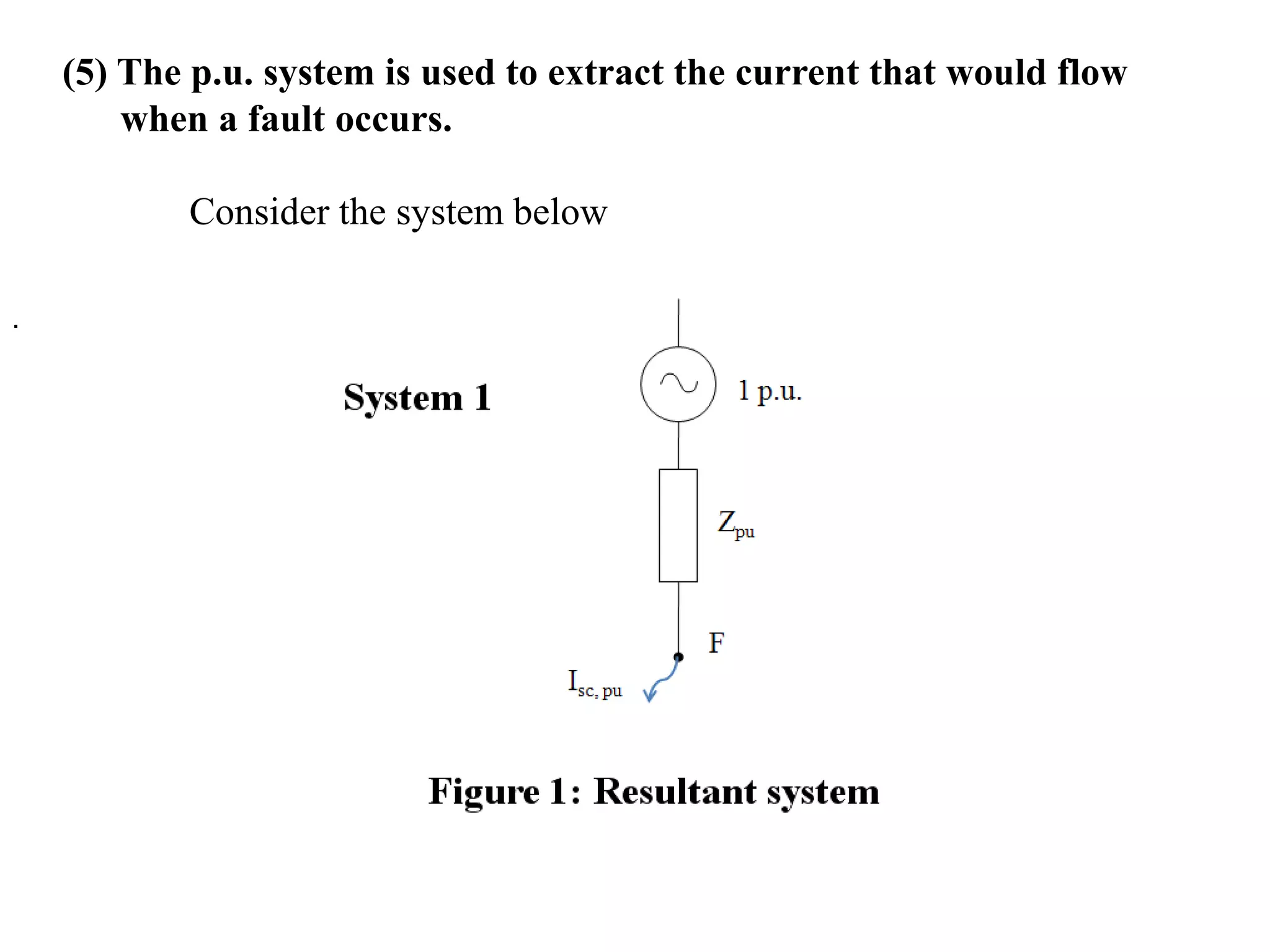
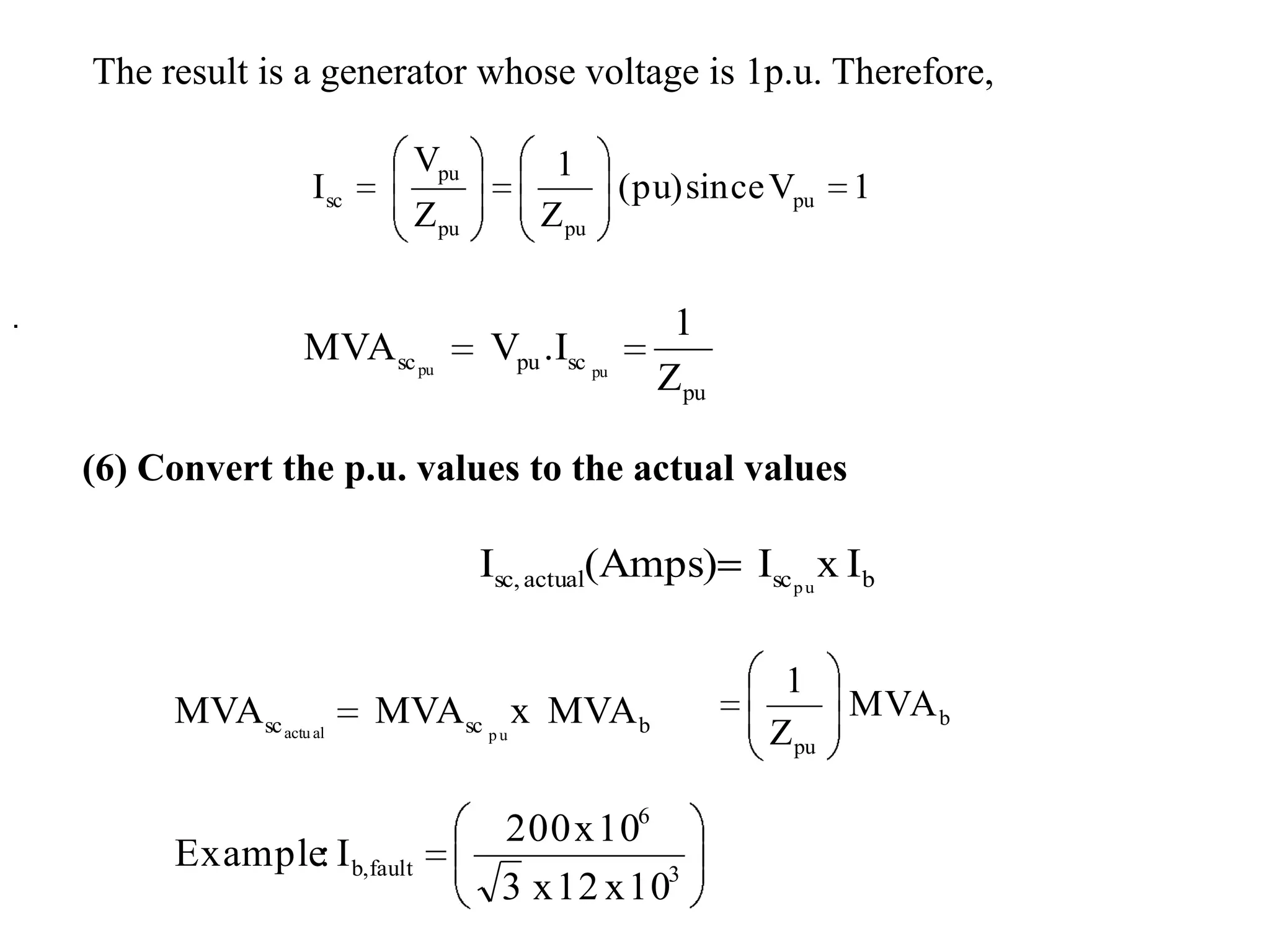
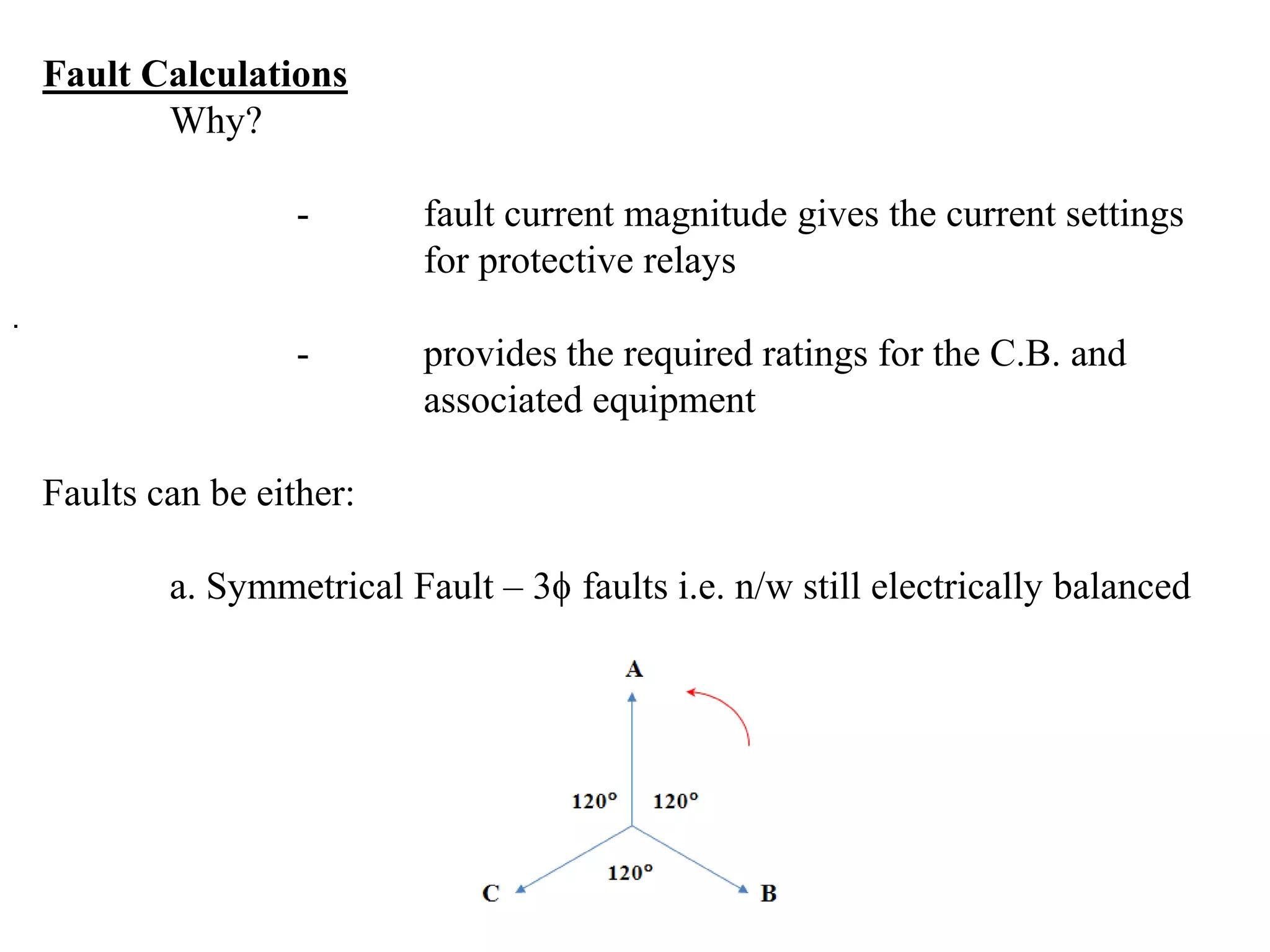
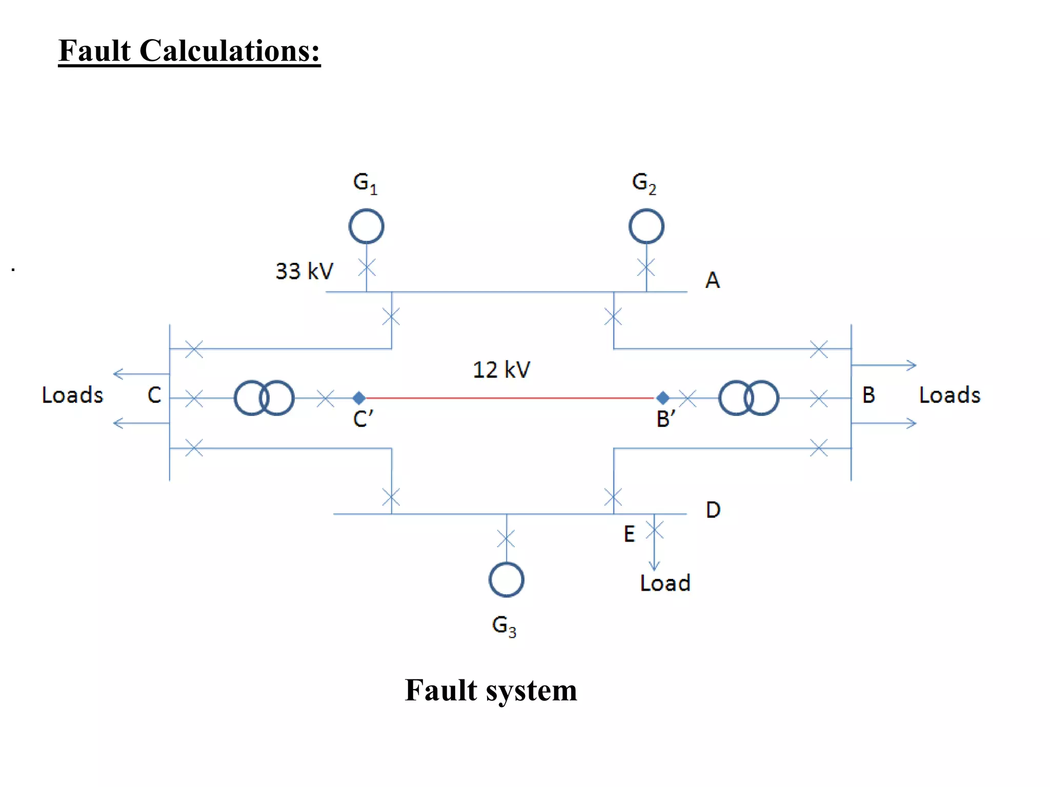
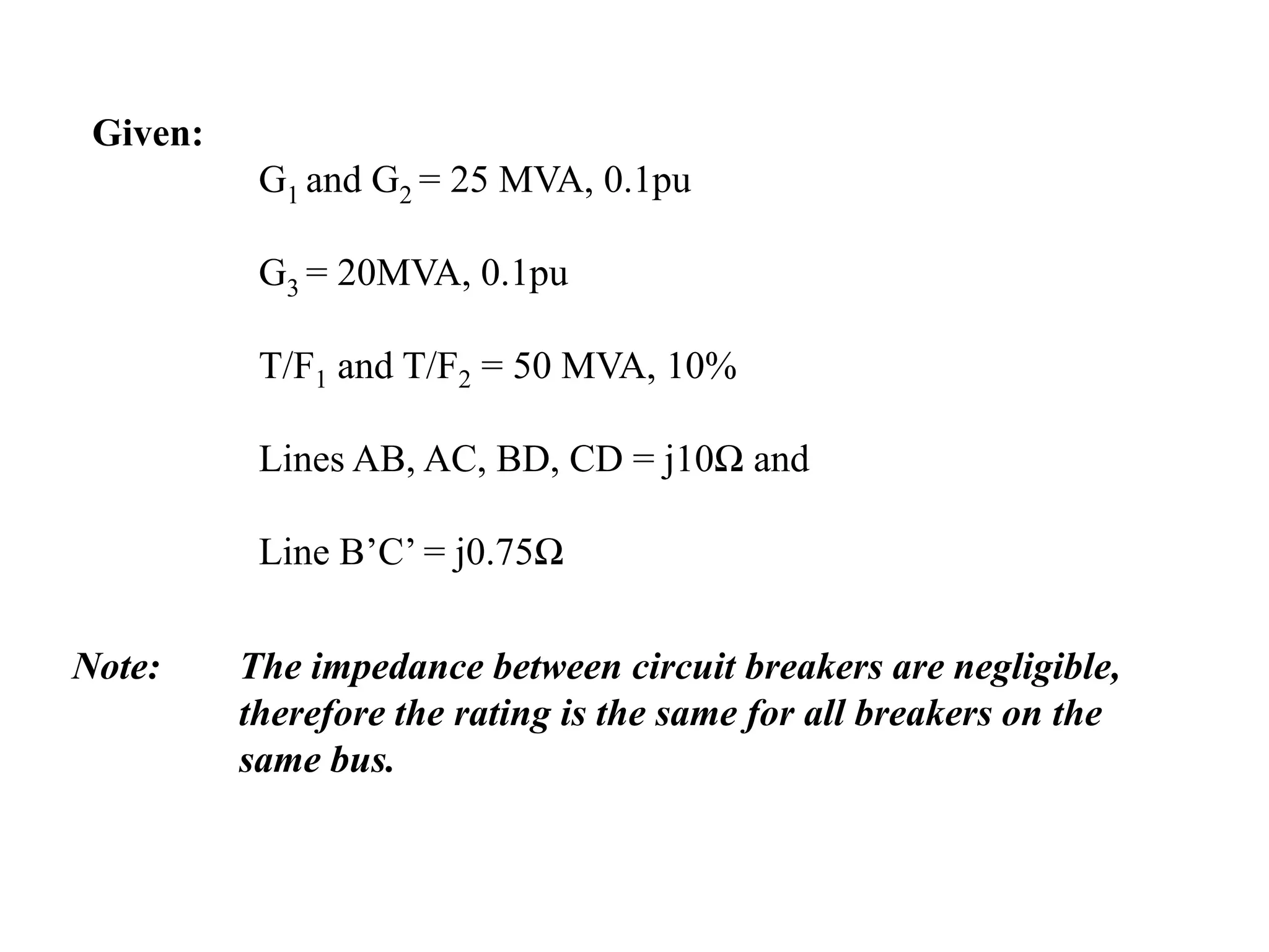
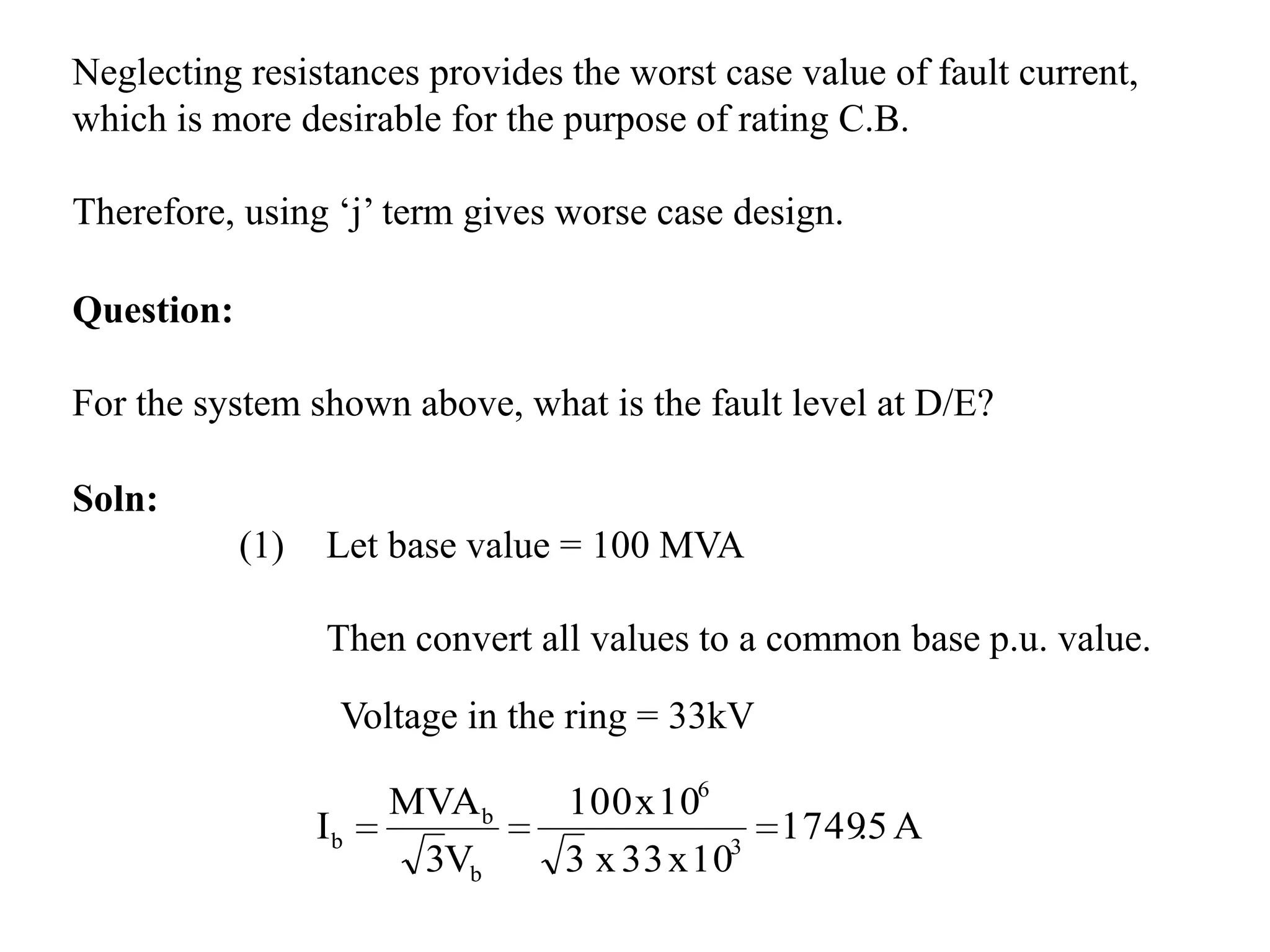
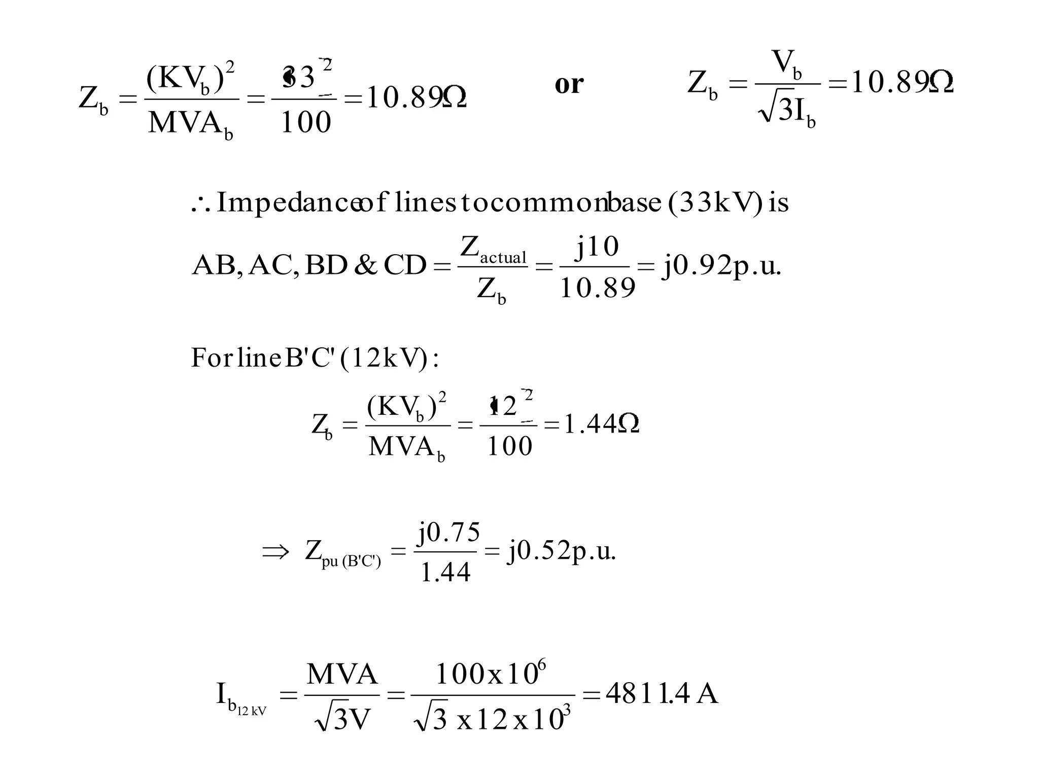
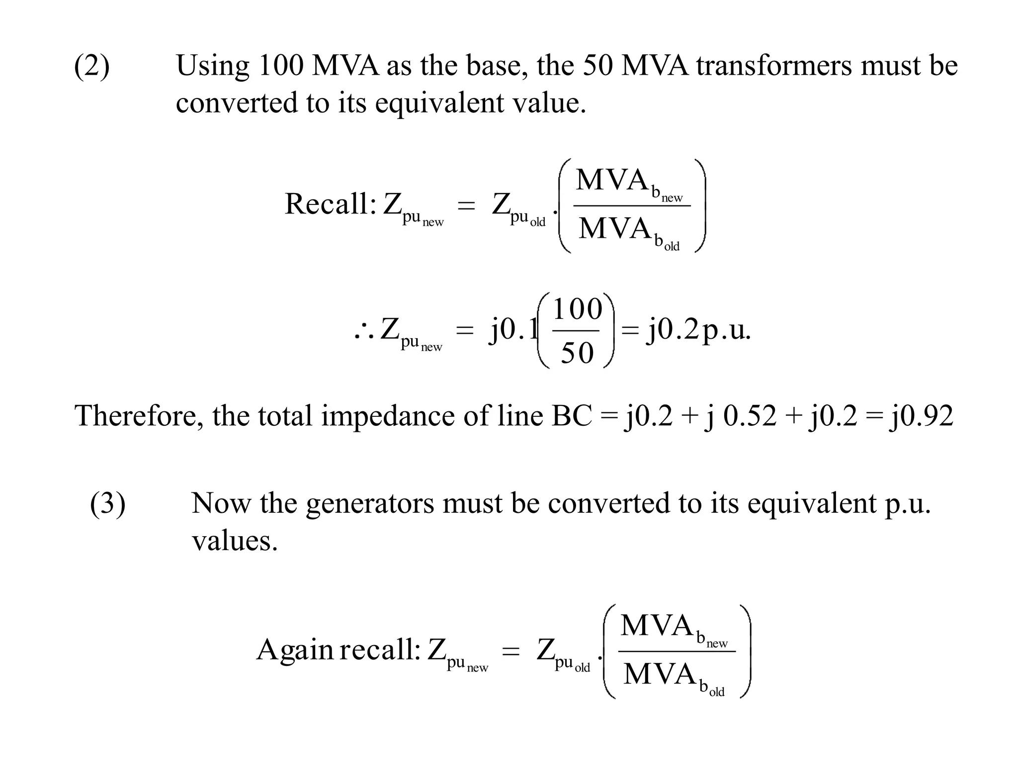
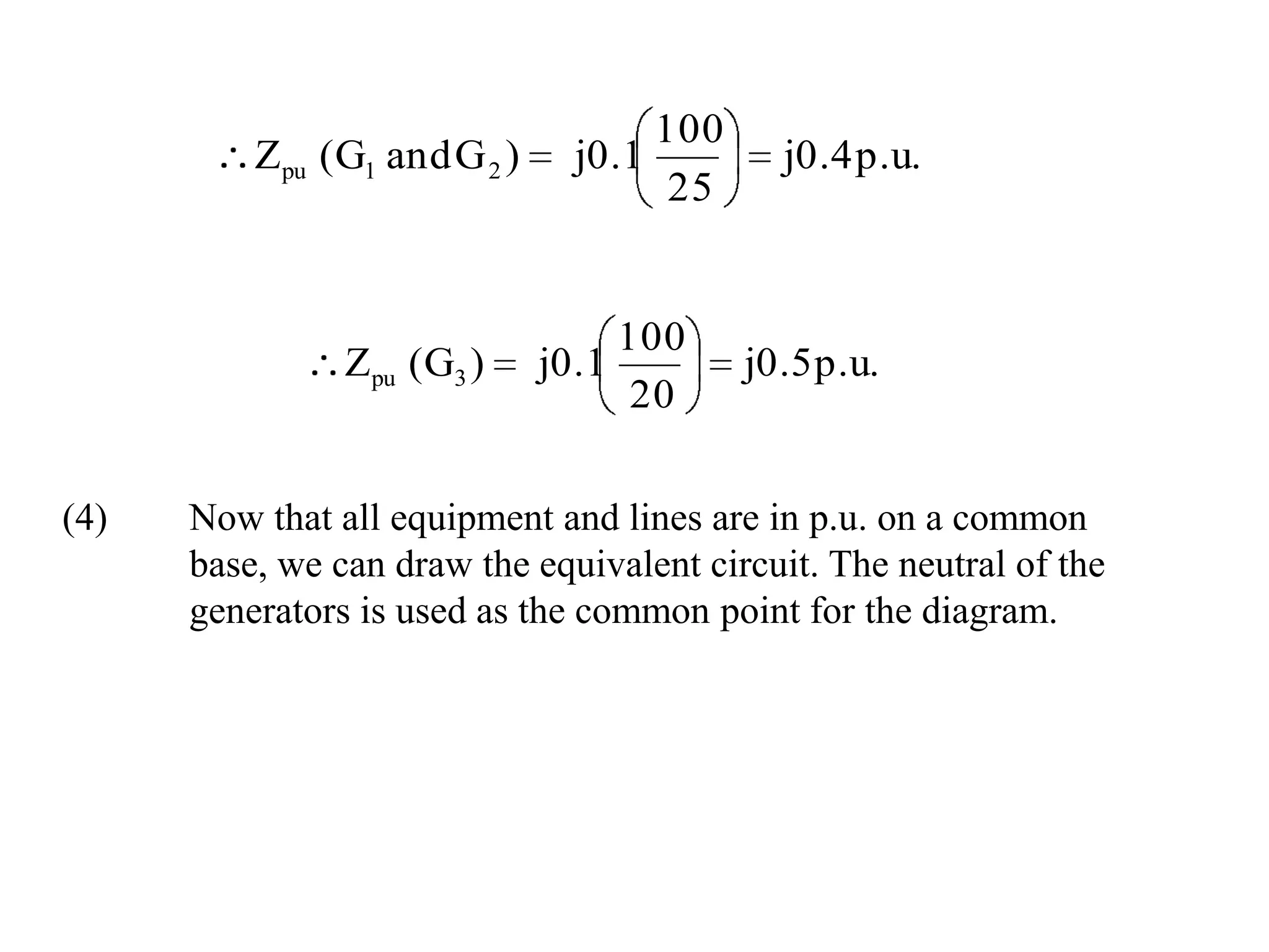
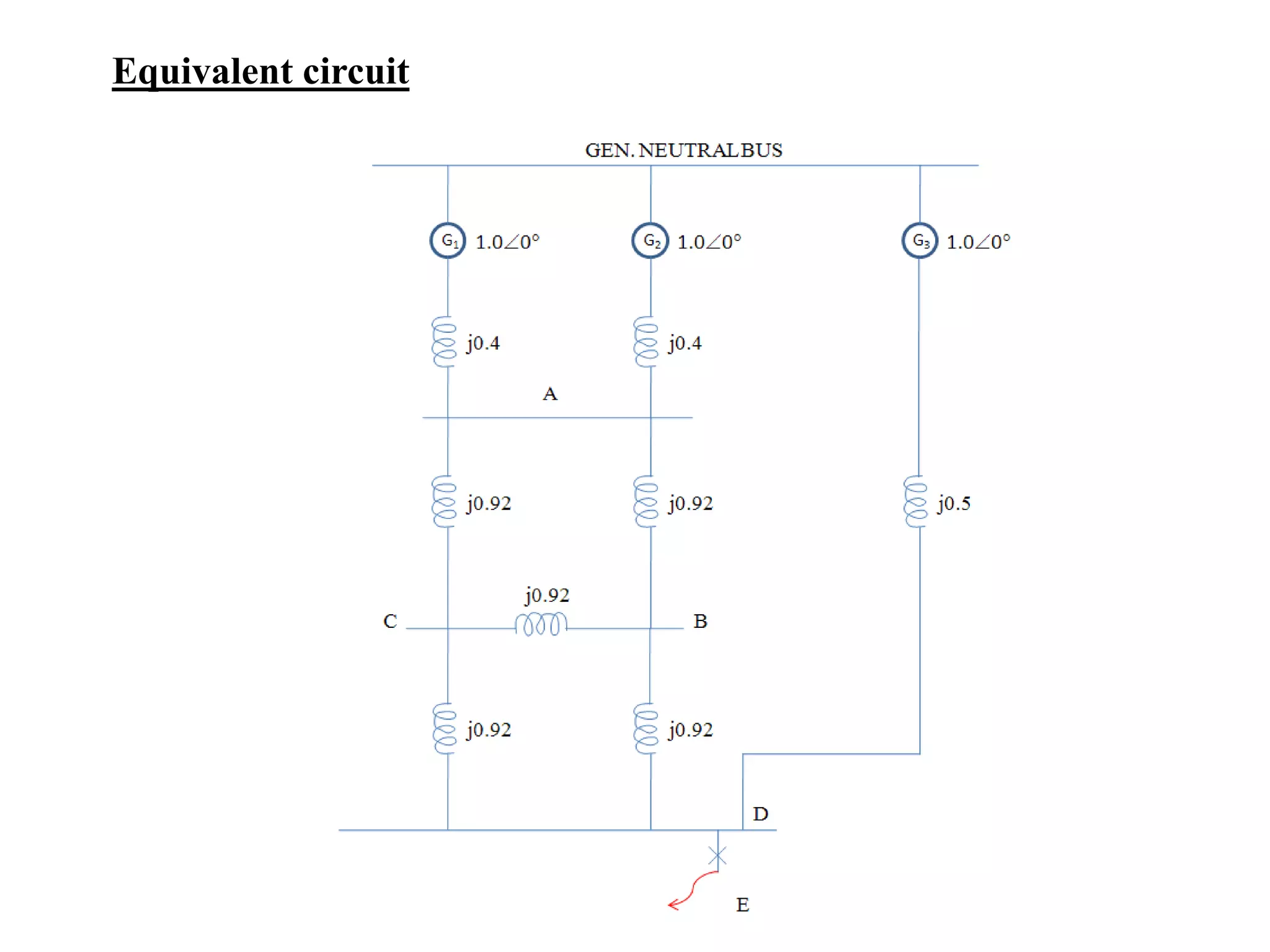
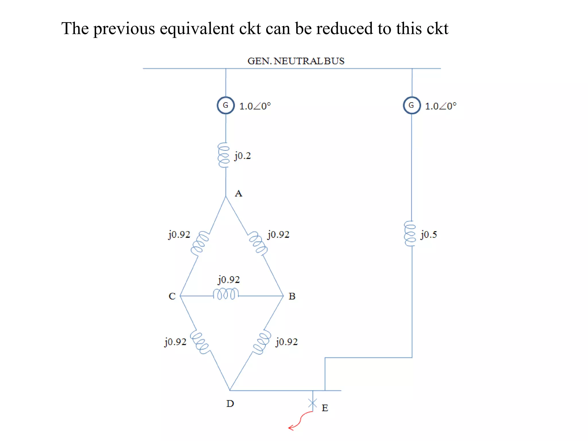
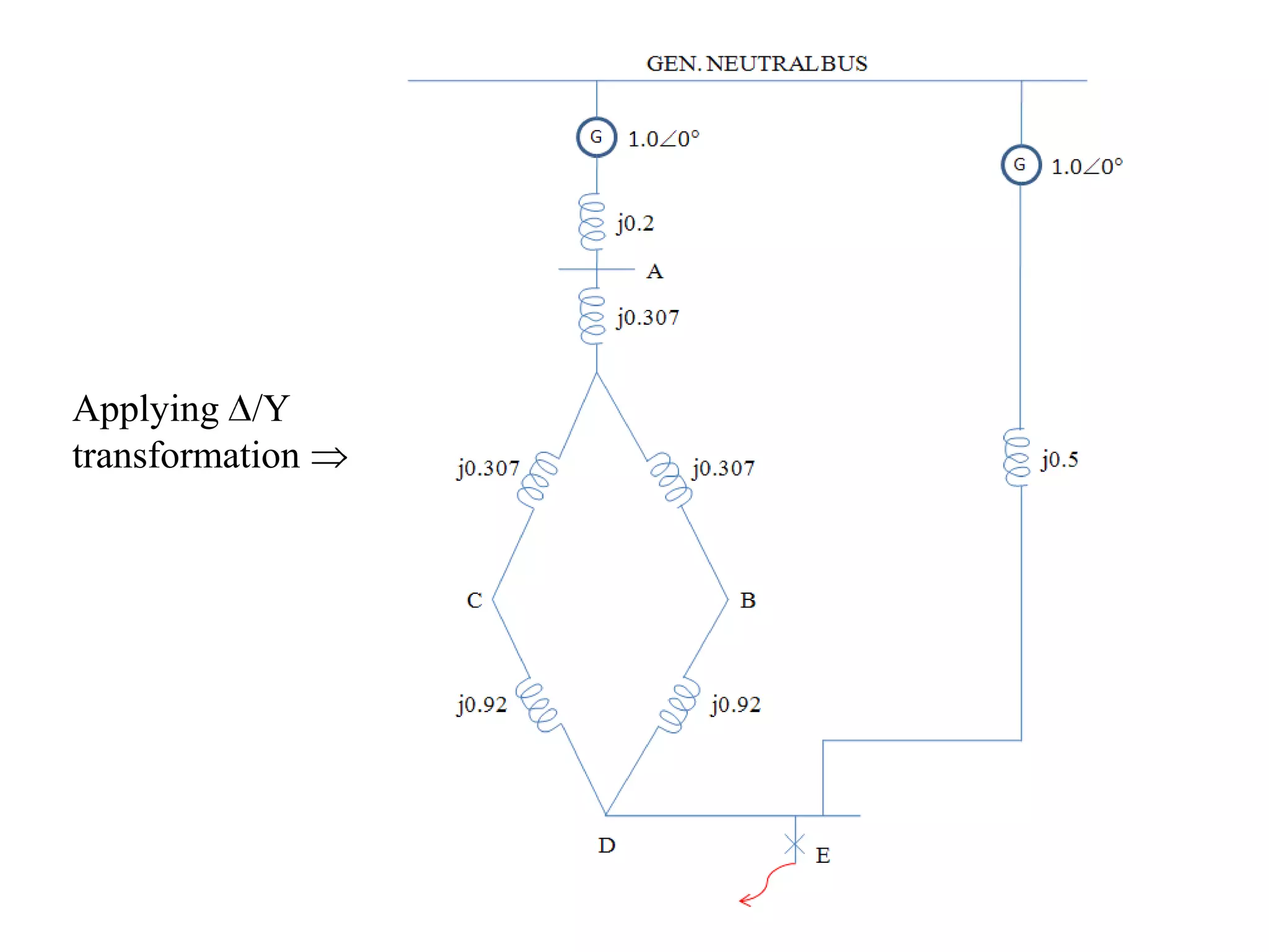
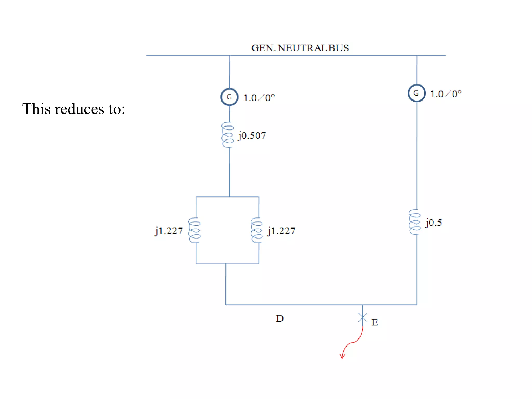
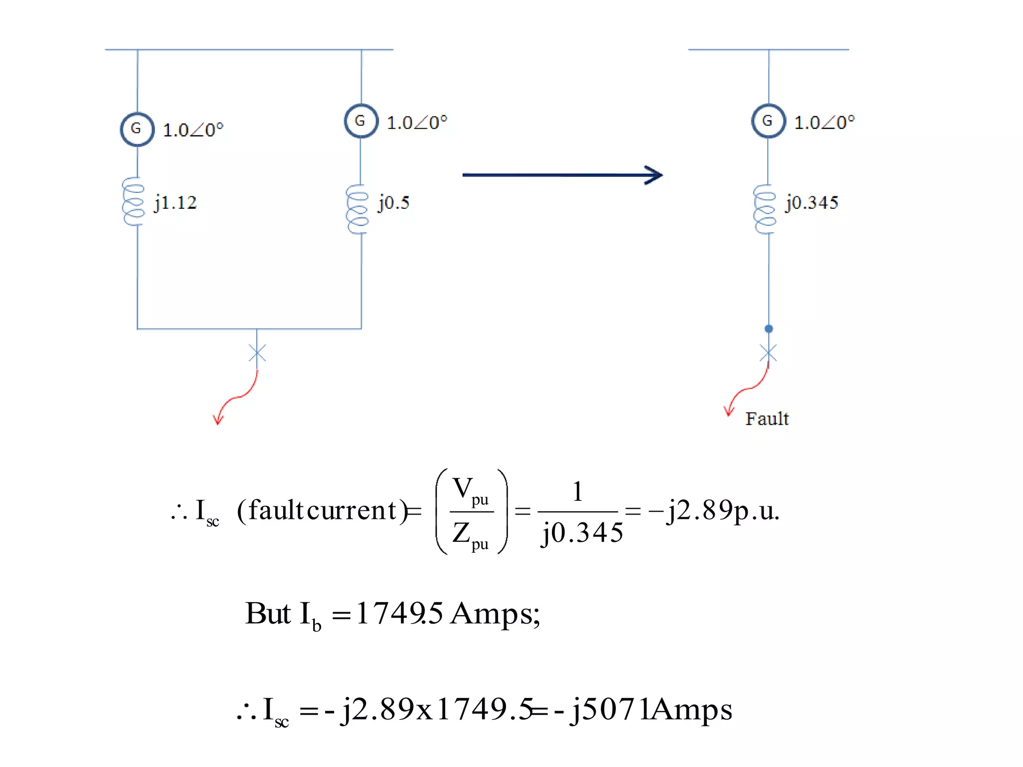
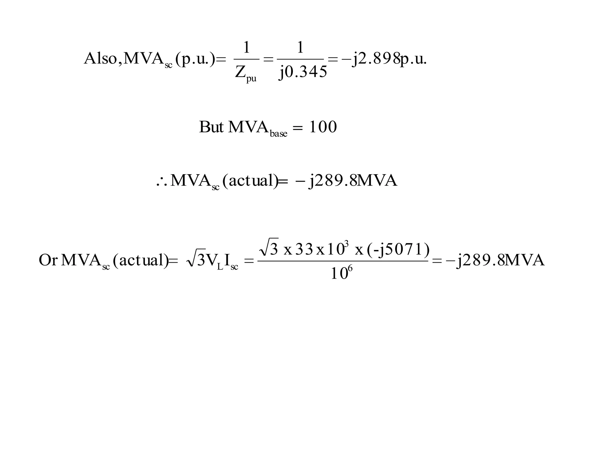
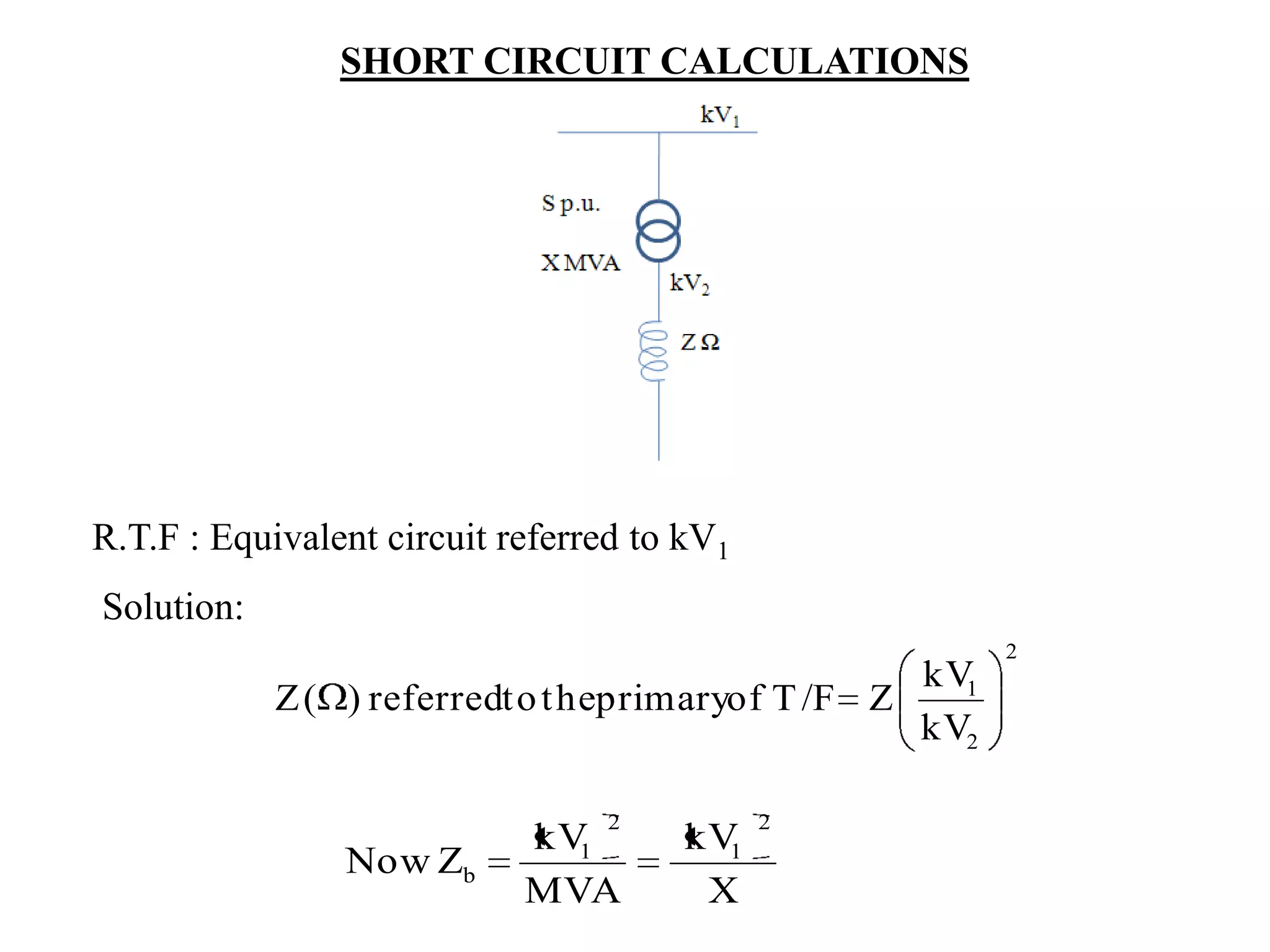
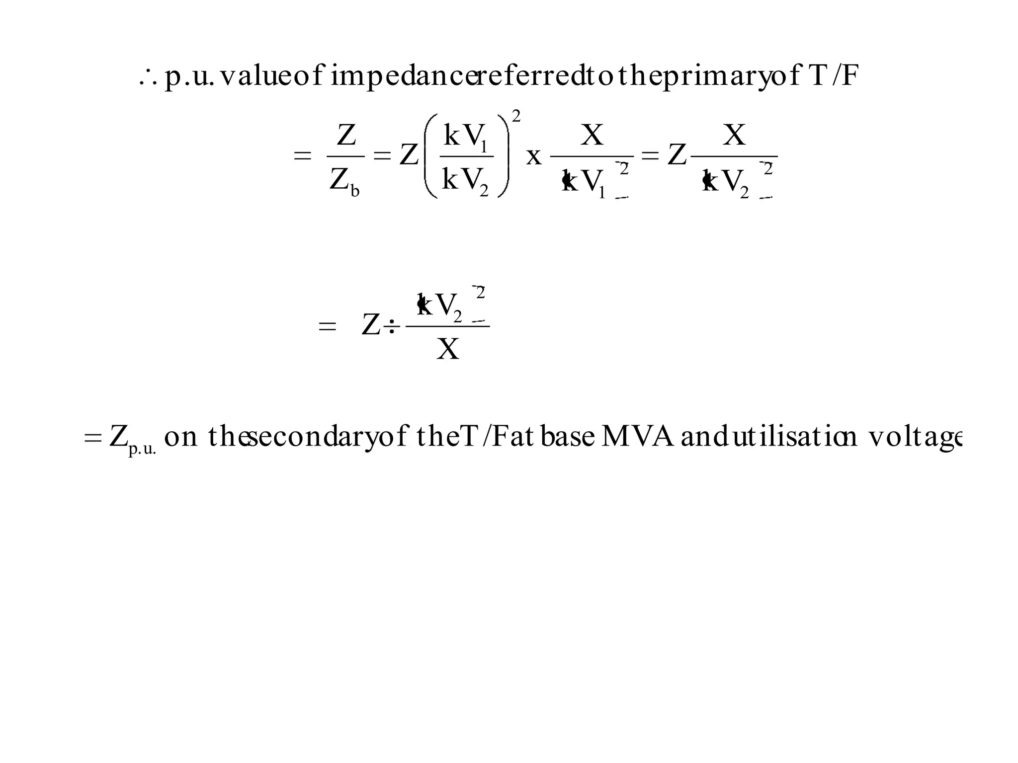
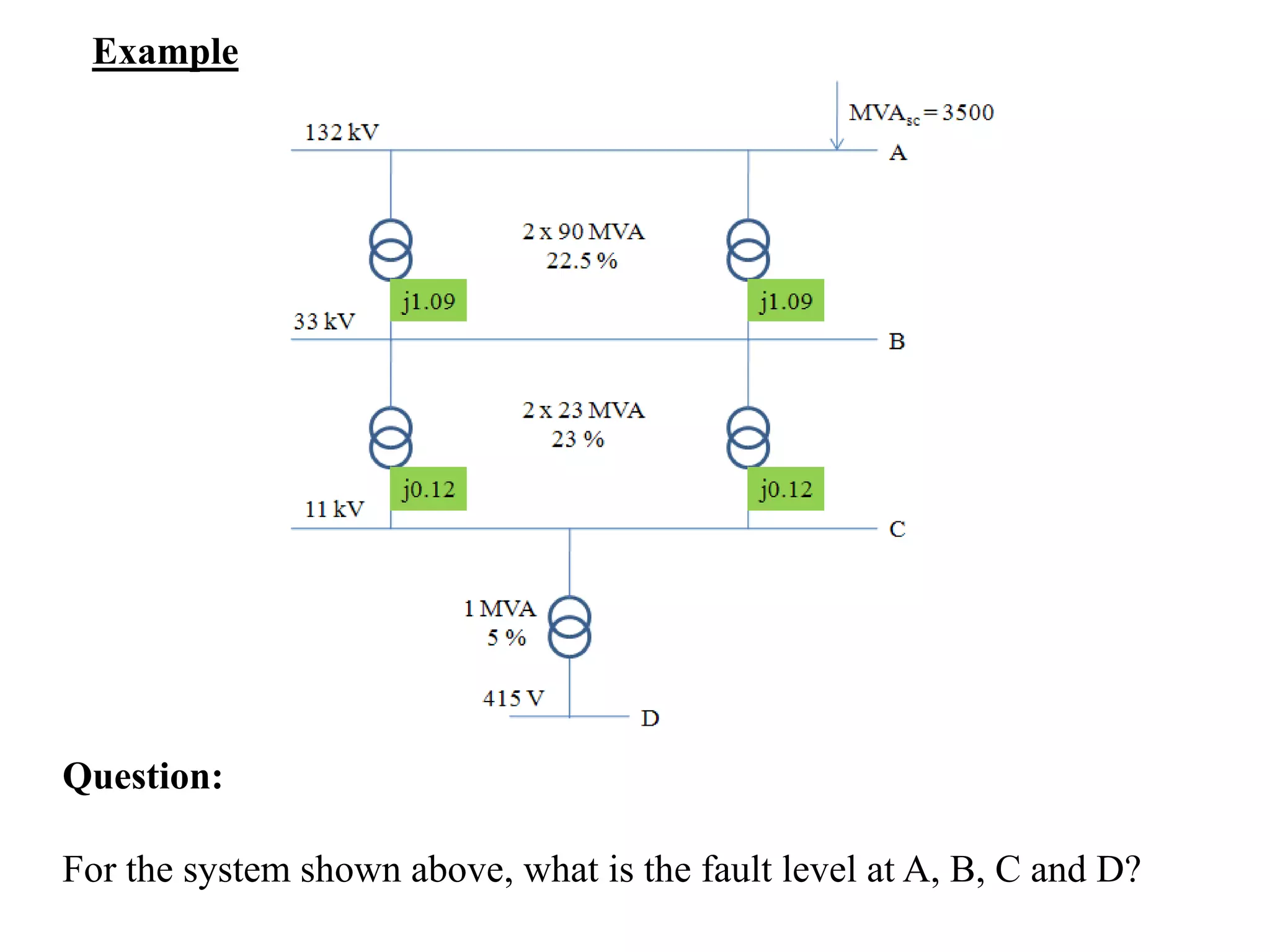
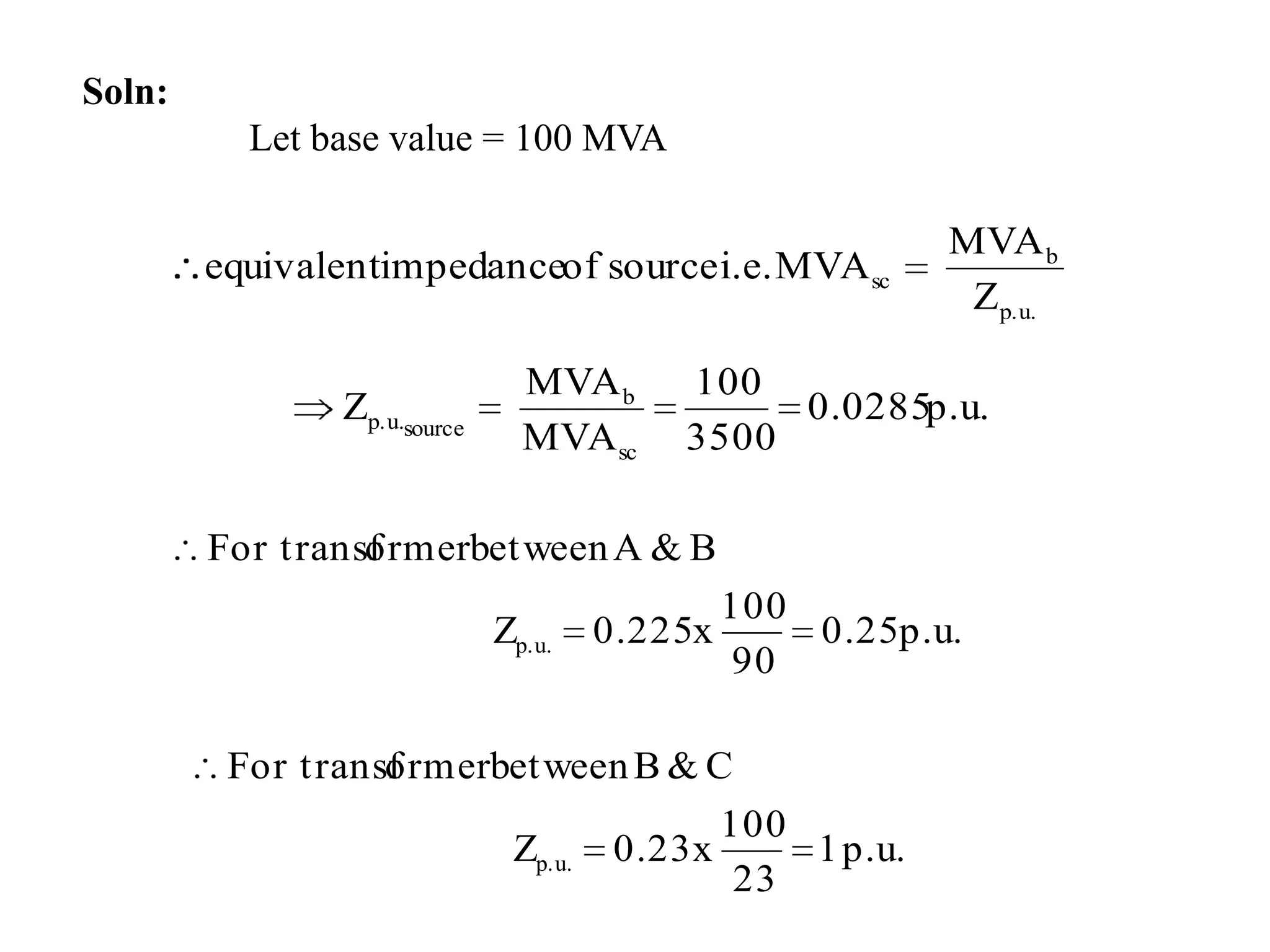
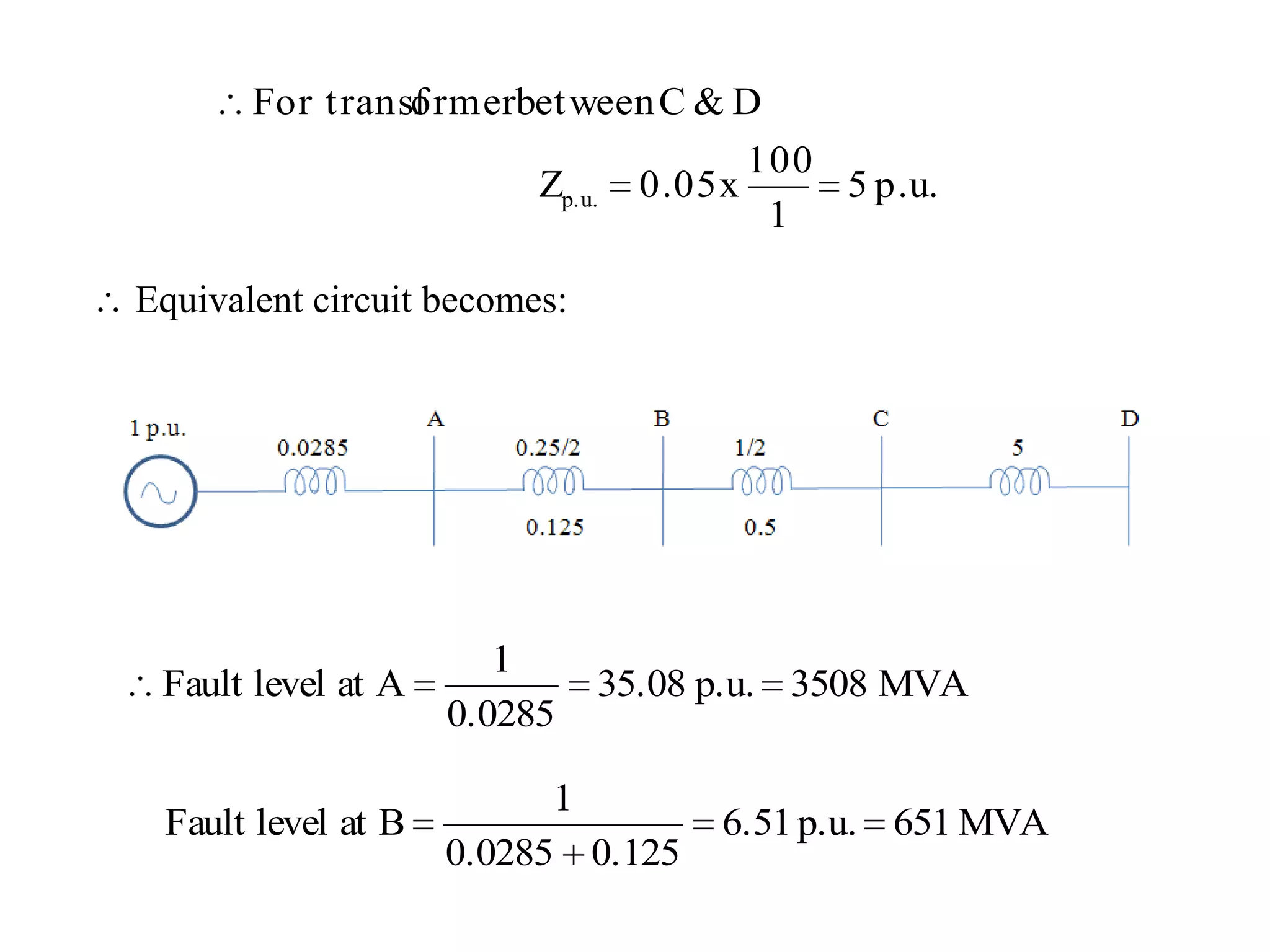
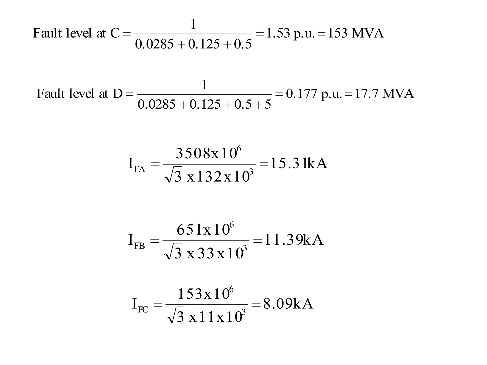
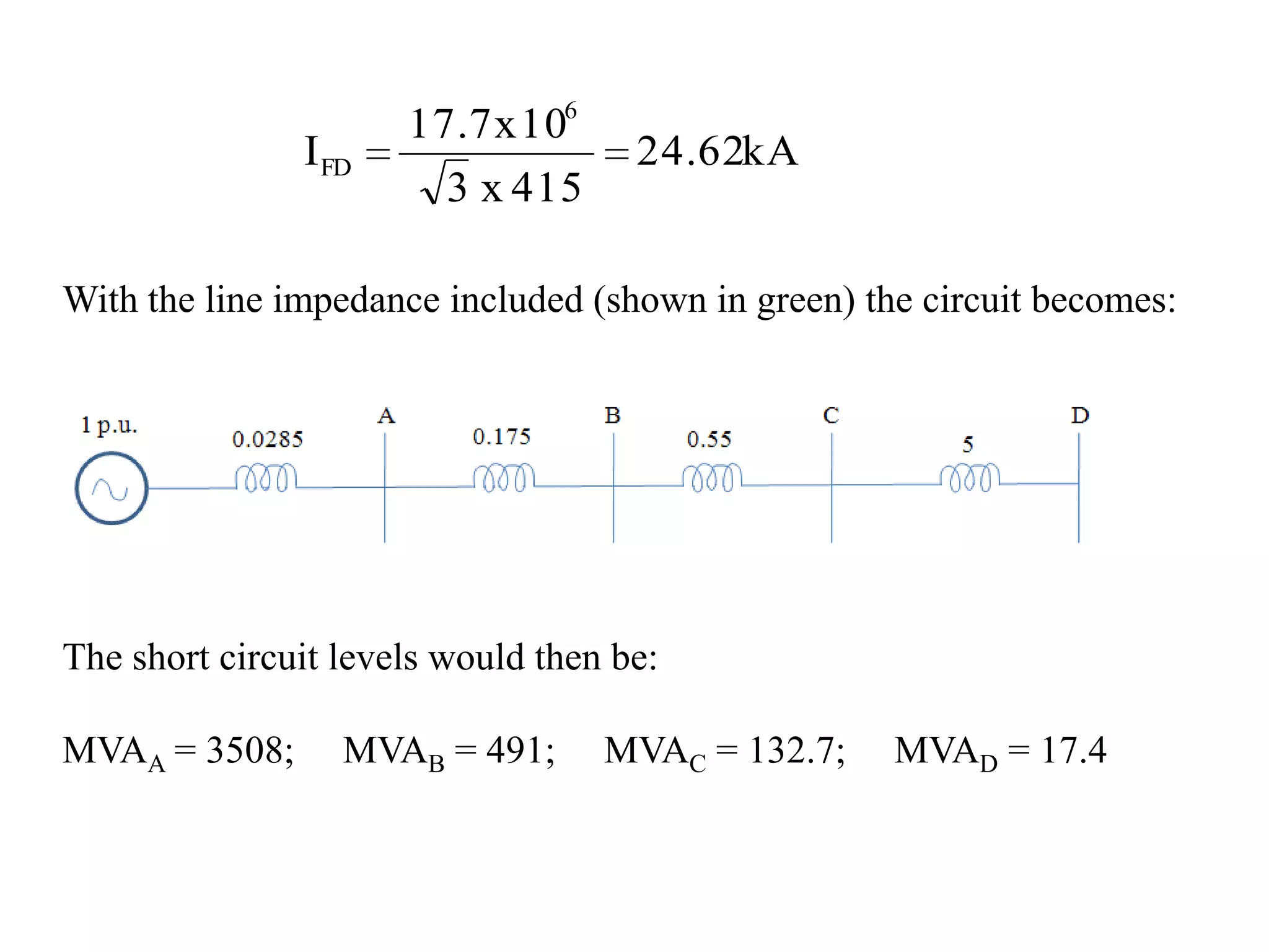
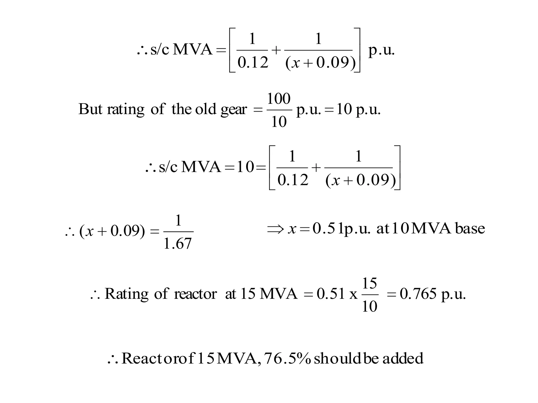
ECNG 3015Industrial and Commercial Electrical SystemsLecturerProf Chandrabhan Sharma# 1PU System
THE PER UNIT SYSTEMIntroduction:The per unit system is fundamental in the analysis of power 	systems  since:		-	parameters such as voltage and power are 			usually in the kilo or mega range in a power 			system 		-	this is due to the large amount of power 				transmitted 		-	other values such as current and impedance 			are usually represented as a percent or per 			unit 		-	determined by using a base or reference 				value.
The per unit system has several advantages which include:	1) Calculations are simplified.	2) Equipment rating.3) Provides a reference to voltages in the power system.	4) It is an international standard.Usually base megavolt amperes (MVA) and base voltage in kilovolts are selected to specify the base.
(2) Per Unit ConversionNote: Apu is dimensionless(3) P.U. Impedance
(4) To compare two power systems with different MVAs.
Example:Given a transformer with the following specifications: 100MVA, 66/12 kV, 0.1 p.u. (10%).If the base value chosen is 200, thenNote: Zp.u. for transformer is the same whether referred to primary or secondary side since the it has the same MVA rating on both sides and turns ratio cancels
(5) The p.u. system is used to extract the current that would flow    when a fault occurs. Consider the system below.
The result is a generator whose voltage is 1p.u. Therefore,. (6) Convert the p.u. values to the actual values
Fault Calculations	Why?		-	fault current magnitude gives the current settings 			for protective relays		-	provides the required ratings for the C.B. and 				associated equipmentFaults can be either:	a. Symmetrical Fault – 3 faults i.e. n/w still electrically balanced.
b. Unsymmetrical – network not electrically balanced - SLG, DLG, OC 		   – analysis done by symmetrical componentsThe most common fault is the Single Line to Ground Fault (SLG) which occurs over 90% of the time.. Note: 	If the system is unbalanced, the relationship V = IR does not hold.The operating time of C.B. for clearing a fault is very important in determining fault levelsIf C.B. operating time  2 cycles after fault initiation then motor contribution to fault currents cannot be ignored.During the first few cycles of a fault, the motors initially act as generators for which the source of excitation is the stored magnetic energy.
In the 1st half cycle of s/c a motor can feed current of magnitudes reaching 10 times the F.L.C.After 5 cycles this current would have decayed to practically ‘0’.Depending on the analysis time frame (re: motors….)	Xd’’, Xd’ and Xd would be used .
Circuit Breakers:	Circuit breakers are needed to:		-	isolate equipment for maintenance and		-	interrupt load and fault current. Transient Impedance Graph
.
Fault Calculations:. Fault system
Given: 	G1 and G2 = 25 MVA, 0.1pu	G3 = 20MVA, 0.1pu	T/F1 and T/F2 = 50 MVA, 10%	Lines AB, AC, BD, CD = j10Ω and 	Line B’C’ = j0.75ΩNote: 	The impedance between circuit breakers are negligible, 	therefore the rating is the same for all breakers on the 	same bus.
Neglecting resistances provides the worst case value of fault current, which is more desirable for the purpose of rating C.B. Therefore, using ‘j’ term gives worse case design.Question: For the system shown above, what is the fault level at D/E?Soln:(1)	Let base value = 100 MVAThen convert all values to a common base p.u. value.Voltage in the ring = 33kV
or
(2)	Using 100 MVA as the base, the 50 MVA transformers must be 	converted to its equivalent value.Therefore, the total impedance of line BC = j0.2 + j 0.52 + j0.2 = j0.92(3) 	Now the generators must be converted to its equivalent p.u. 	values.
(4)	Now that all equipment and lines are in p.u. on a common 	base, we can draw the equivalent circuit. The neutral of the   	generators is used as the common point for the diagram.
Equivalent circuit
The previous equivalent ckt can be reduced to this ckt
Applying /Y transformation 
This reduces to:
SHORT CIRCUIT CALCULATIONSR.T.F : Equivalent circuit referred to kV1Solution:
ExampleQuestion: For the system shown above, what is the fault level at A, B, C and D?
Soln:	Let base value = 100 MVA
 Equivalent circuit becomes:
With the line impedance included (shown in green) the circuit becomes:The short circuit levels would then be:MVAA = 3508;     MVAB = 491;     MVAC = 132.7;     MVAD = 17.4
Limiting S/C levelsThere are basically two methods 		a.	Sectionalizers		b.	Reactorsa. SectionalizersN.B.: care must be taken in paralleling cables between buses.
Practical case is where bus interconnect via a cable. If the existing cable is overloaded then a second cable may be  installed to assist in carrying the load as shown belowThis will have the effect of increasing the fault level at B.
b. Reactors-	means of increasing the impedance artificially 		by the introduction of reactorsExample:Given an old system with switchgear rated at 100 MVA where we need to expand by adding a new feeder and associated switchgear. New rating of added switchgear is 250 MVA. In order to connect both systems, a series reactor of 15 MVA rating is to be introduced. Find the value of the reactance required.
Soln:	Let base value = 10 MVA	Reactance of G1 & G2 to new base = 0.24 p.u.
Equivalent circuit
Question:Determine the fault level at the new station busbar (B). (Ans. 126.9 MVA)Disadvantages of adding reactors:	-	increased regulation	-	lowering of power factor	-	increase in system losses

ECNG 3015 - PU system and 3Phase Fault calculation

  • 1.
    ECNG 3015Industrial andCommercial Electrical SystemsLecturerProf Chandrabhan Sharma# 1PU System
  • 2.
    THE PER UNITSYSTEMIntroduction:The per unit system is fundamental in the analysis of power systems since: - parameters such as voltage and power are usually in the kilo or mega range in a power system - this is due to the large amount of power transmitted - other values such as current and impedance are usually represented as a percent or per unit - determined by using a base or reference value.
  • 3.
    The per unitsystem has several advantages which include: 1) Calculations are simplified. 2) Equipment rating.3) Provides a reference to voltages in the power system. 4) It is an international standard.Usually base megavolt amperes (MVA) and base voltage in kilovolts are selected to specify the base.
  • 4.
    (2) Per UnitConversionNote: Apu is dimensionless(3) P.U. Impedance
  • 5.
    (4) To comparetwo power systems with different MVAs.
  • 6.
    Example:Given a transformerwith the following specifications: 100MVA, 66/12 kV, 0.1 p.u. (10%).If the base value chosen is 200, thenNote: Zp.u. for transformer is the same whether referred to primary or secondary side since the it has the same MVA rating on both sides and turns ratio cancels
  • 7.
    (5) The p.u.system is used to extract the current that would flow when a fault occurs. Consider the system below.
  • 8.
    The result isa generator whose voltage is 1p.u. Therefore,. (6) Convert the p.u. values to the actual values
  • 9.
    Fault Calculations Why? - fault currentmagnitude gives the current settings for protective relays - provides the required ratings for the C.B. and associated equipmentFaults can be either: a. Symmetrical Fault – 3 faults i.e. n/w still electrically balanced.
  • 10.
    b. Unsymmetrical –network not electrically balanced - SLG, DLG, OC – analysis done by symmetrical componentsThe most common fault is the Single Line to Ground Fault (SLG) which occurs over 90% of the time.. Note: If the system is unbalanced, the relationship V = IR does not hold.The operating time of C.B. for clearing a fault is very important in determining fault levelsIf C.B. operating time  2 cycles after fault initiation then motor contribution to fault currents cannot be ignored.During the first few cycles of a fault, the motors initially act as generators for which the source of excitation is the stored magnetic energy.
  • 11.
    In the 1sthalf cycle of s/c a motor can feed current of magnitudes reaching 10 times the F.L.C.After 5 cycles this current would have decayed to practically ‘0’.Depending on the analysis time frame (re: motors….) Xd’’, Xd’ and Xd would be used .
  • 12.
    Circuit Breakers: Circuit breakersare needed to: - isolate equipment for maintenance and - interrupt load and fault current. Transient Impedance Graph
  • 13.
  • 14.
  • 15.
    Given: G1 andG2 = 25 MVA, 0.1pu G3 = 20MVA, 0.1pu T/F1 and T/F2 = 50 MVA, 10% Lines AB, AC, BD, CD = j10Ω and Line B’C’ = j0.75ΩNote: The impedance between circuit breakers are negligible, therefore the rating is the same for all breakers on the same bus.
  • 16.
    Neglecting resistances providesthe worst case value of fault current, which is more desirable for the purpose of rating C.B. Therefore, using ‘j’ term gives worse case design.Question: For the system shown above, what is the fault level at D/E?Soln:(1) Let base value = 100 MVAThen convert all values to a common base p.u. value.Voltage in the ring = 33kV
  • 17.
  • 18.
    (2) Using 100 MVAas the base, the 50 MVA transformers must be converted to its equivalent value.Therefore, the total impedance of line BC = j0.2 + j 0.52 + j0.2 = j0.92(3) Now the generators must be converted to its equivalent p.u. values.
  • 19.
    (4) Now that allequipment and lines are in p.u. on a common base, we can draw the equivalent circuit. The neutral of the generators is used as the common point for the diagram.
  • 20.
  • 21.
    The previous equivalentckt can be reduced to this ckt
  • 22.
  • 23.
  • 26.
    SHORT CIRCUIT CALCULATIONSR.T.F: Equivalent circuit referred to kV1Solution:
  • 28.
    ExampleQuestion: For thesystem shown above, what is the fault level at A, B, C and D?
  • 29.
  • 30.
  • 32.
    With the lineimpedance included (shown in green) the circuit becomes:The short circuit levels would then be:MVAA = 3508; MVAB = 491; MVAC = 132.7; MVAD = 17.4
  • 33.
    Limiting S/C levelsThereare basically two methods a. Sectionalizers b. Reactorsa. SectionalizersN.B.: care must be taken in paralleling cables between buses.
  • 34.
    Practical case iswhere bus interconnect via a cable. If the existing cable is overloaded then a second cable may be installed to assist in carrying the load as shown belowThis will have the effect of increasing the fault level at B.
  • 35.
    b. Reactors- means ofincreasing the impedance artificially by the introduction of reactorsExample:Given an old system with switchgear rated at 100 MVA where we need to expand by adding a new feeder and associated switchgear. New rating of added switchgear is 250 MVA. In order to connect both systems, a series reactor of 15 MVA rating is to be introduced. Find the value of the reactance required.
  • 36.
    Soln: Let base value= 10 MVA Reactance of G1 & G2 to new base = 0.24 p.u.
  • 37.
  • 39.
    Question:Determine the faultlevel at the new station busbar (B). (Ans. 126.9 MVA)Disadvantages of adding reactors: - increased regulation - lowering of power factor - increase in system losses