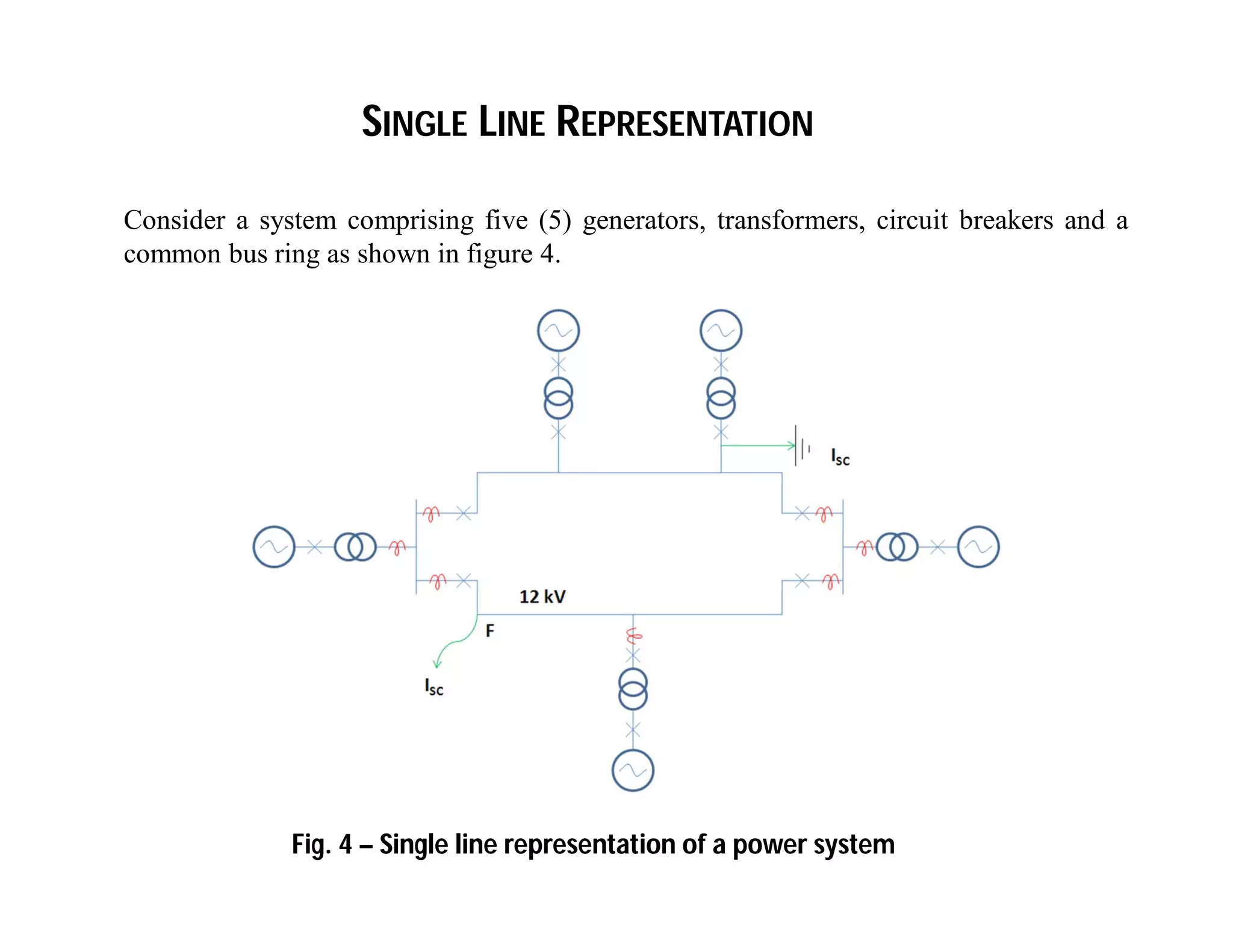
ECNG 3015 - COURSE OUTLINE
This course comprise the following modules:
1. Per Unit System (reasons and importance of its use)
2. Fault calculation on ‘small’ systems (types of faults how to analyze
them)
3. Power System and Overcurrent Protection (reasons for protection,
equipment used and how they work together)
4. Introduction to Switchgear technology (types of switchgear and how
they work)
5. Earthing and System Grounding (reason for earthing and grounding)
6. Illumination Engineering (the eye and how it responds to light as
well as basic lighting design)
Introduction – Need to Know
 
Z
iV
m
m
im
Vm
Z
I
V
I
V









Z
Z
Passive Element Impedance
R Z = R
L Z = jXL = jL = L 90° (where XL = L)
C Z = 1/ jC = -jXC = 1/C -90° (where XC = (1/C)
 









R
X
tan
andXRZWhere
jXRZ
circuit,inductiveFor
1-
Z
22
Z

Z
Phase voltages:
Star Connection
Figure 1 – Star (Wye) connected system



120or240
120
0
cncn
bnbn
anan
VV
VV
VV
Determination of Line – Line (or simply Line) voltages:
Where:
Vab is the Line – Line voltage and
Vph is the magnitude of the phase voltage
 Note: In a star-star connection, the line current = phase current


303
1200
phab
bnanbnanab
VV
VVVVV



303
903
303
analysissimilaraUsing
phca
phbc
phab
VV
VV
VV
Where Vph is phase voltage referenced to the system in Fig. 2
Figure 2 – Delta connected system
Delta Connection




240
120
0
:arevoltagesphaseandlinebetweeniprelationshThe
and-connectionDeltatheofcasetheIn
Lineca
Linebc
Lineab
Lineph
VV
VV
VV
VV
  
  
  
132312
2313
3
132312
2312
2
132312
1312
1
ZZZ
ZZ
Z
ZZZ
ZZ
Z
ZZZ
ZZ
Z
3aFig.Refer to






Fig. 3a
Delta to Star Conversion
  
  
  
1
32
3223
2
31
3113
3
21
2112
Z
ZZ
ZZZ
Z
ZZ
ZZZ
Z
ZZ
ZZZ
3bFig.Refer to



Fig. 3b
Star to Delta Conversion
Typically, a three-phase power system:
- is considered balanced
- is represented on a single line diagram
- easy to analyze using single line representation
In reality, the transmission system is typically balanced but not the
distribution system.
Consider a system comprising five (5) generators, transformers, circuit breakers and a
common bus ring as shown in figure 4.
SINGLE LINE REPRESENTATION
Fig. 4 – Single line representation of a power system
Typically, a power system comprises:
- Generators – V, MVA, per unit impedance, short circuit rating
- Transformers – MVA, V, per unit impedance, transformer ratio, short circuit
rating Cooling method (ONAN, ONAF, OFAF)
- Circuit breakers – MVA, continuous rating, short-circuit rating, principle of
arc extinguishing (eg. Air, Oil, Vacuum and Gas)
Functions of the equipment :
- Generators generate the power
- Transformers are used to bring the voltage of the generators
to a common voltage for the common bus ring, i.e. step up or down.
- The circuit breakers are used to isolate equipment in case of a
fault.
TYPICAL COMPONENTS OF A POWER SYSTEM & THEIR FUNCTION
Power system typically utilize either fuses or relays for protection against faults.
Fuses – used to isolate fault once fuse rating is exceeded
Protection relays - to detect fault condition and ‘relay’ signal to circuit breaker to
open and isolate the faulted equipment.
Since short-circuit rating of the power system equipment is ‘time-rated’, if the
protection system fail to clear the fault then equipment damage can occur.
In such instances, back-up protection is imperative.
POWER SYSTEM PROTECTION

ECNG 3015 chapter 1 - Basics

  • 1.
    ECNG 3015 -COURSE OUTLINE This course comprise the following modules: 1. Per Unit System (reasons and importance of its use) 2. Fault calculation on ‘small’ systems (types of faults how to analyze them) 3. Power System and Overcurrent Protection (reasons for protection, equipment used and how they work together) 4. Introduction to Switchgear technology (types of switchgear and how they work) 5. Earthing and System Grounding (reason for earthing and grounding) 6. Illumination Engineering (the eye and how it responds to light as well as basic lighting design)
  • 2.
    Introduction – Needto Know   Z iV m m im Vm Z I V I V          Z Z Passive Element Impedance R Z = R L Z = jXL = jL = L 90° (where XL = L) C Z = 1/ jC = -jXC = 1/C -90° (where XC = (1/C)            R X tan andXRZWhere jXRZ circuit,inductiveFor 1- Z 22 Z  Z
  • 3.
    Phase voltages: Star Connection Figure1 – Star (Wye) connected system    120or240 120 0 cncn bnbn anan VV VV VV
  • 4.
    Determination of Line– Line (or simply Line) voltages: Where: Vab is the Line – Line voltage and Vph is the magnitude of the phase voltage  Note: In a star-star connection, the line current = phase current   303 1200 phab bnanbnanab VV VVVVV    303 903 303 analysissimilaraUsing phca phbc phab VV VV VV
  • 5.
    Where Vph isphase voltage referenced to the system in Fig. 2 Figure 2 – Delta connected system Delta Connection     240 120 0 :arevoltagesphaseandlinebetweeniprelationshThe and-connectionDeltatheofcasetheIn Lineca Linebc Lineab Lineph VV VV VV VV
  • 6.
            132312 2313 3 132312 2312 2 132312 1312 1 ZZZ ZZ Z ZZZ ZZ Z ZZZ ZZ Z 3aFig.Refer to       Fig. 3a Delta to Star Conversion
  • 7.
            1 32 3223 2 31 3113 3 21 2112 Z ZZ ZZZ Z ZZ ZZZ Z ZZ ZZZ 3bFig.Refer to    Fig. 3b Star to Delta Conversion
  • 8.
    Typically, a three-phasepower system: - is considered balanced - is represented on a single line diagram - easy to analyze using single line representation In reality, the transmission system is typically balanced but not the distribution system.
  • 9.
    Consider a systemcomprising five (5) generators, transformers, circuit breakers and a common bus ring as shown in figure 4. SINGLE LINE REPRESENTATION Fig. 4 – Single line representation of a power system
  • 10.
    Typically, a powersystem comprises: - Generators – V, MVA, per unit impedance, short circuit rating - Transformers – MVA, V, per unit impedance, transformer ratio, short circuit rating Cooling method (ONAN, ONAF, OFAF) - Circuit breakers – MVA, continuous rating, short-circuit rating, principle of arc extinguishing (eg. Air, Oil, Vacuum and Gas) Functions of the equipment : - Generators generate the power - Transformers are used to bring the voltage of the generators to a common voltage for the common bus ring, i.e. step up or down. - The circuit breakers are used to isolate equipment in case of a fault. TYPICAL COMPONENTS OF A POWER SYSTEM & THEIR FUNCTION
  • 15.
    Power system typicallyutilize either fuses or relays for protection against faults. Fuses – used to isolate fault once fuse rating is exceeded Protection relays - to detect fault condition and ‘relay’ signal to circuit breaker to open and isolate the faulted equipment. Since short-circuit rating of the power system equipment is ‘time-rated’, if the protection system fail to clear the fault then equipment damage can occur. In such instances, back-up protection is imperative. POWER SYSTEM PROTECTION